Available online:
https://edupediapublications.org/journals/index.php/IJR/
P a g e | 2131
Optimization of Helic, Opter Rotor Blade by Using Ansys Software
1
pinintisairam Reddy,
2S Mohan Kumar,
3Dr. B Nageshwara Rao
1
M.Tech student,
2Assistant professor,
3Assistant professor. Department of Mechanical
Engineering, Avn Institute of Engineering and Technology, Hyd, T.S
ABSTRACT
The blade of the helicopter was affected by flow of air. The effects or loads caused by both aerodynamic action and centrifugal action are considered for analysis of the blade. The objective is to reduce the weight of the blade to reduce the load caused by aerodynamic load. The weight of the blade can be reduced by choosing of alternative material. Selection of alternative material (i.e. to reduce the weight) is called as optimization. The alternative material should have less weight and high stiffness. The optimization can be done by CAE package.
The objective of the project is to perform the structural analysis on the helicopter blade. Structural analysis involves both static and modal analysis. In static analysis, deflections and stresses are documented for forces due to aerodynamic action of the blade. Then modal analysis is performed to determine the natural frequencies. Based on the natural frequencies, the stiffness of the material can be determined. The structural analysis of the blade is performed for different materials (aluminum alloy and Eglass Epoxy and Carbon Epoxy materials). Based on the analysis results, best material is preferred. NX-CAD software is used to model the blade and ANSYS software is used for analysis of the blade.
INTRODUCTION
During the motion of the airplane or helicopter in the air, lift force was created by wings of the airplane or helicopter. Generally four forces are impacted on the helicopter in the flight of the helicopter. They are LIFT, DRAG, THRUST, and WEIGHT. As we know that, the movement of the helicopter is due movement of wings. In the movement of helicopter, the body of the helicopter is stationary while the wings are moving along with the helicopter. Those helicopter wings are called as Main Rotor Blades. Lift force is determined by the design
of the blade. The design of blade incudes design angle of the blades and shape of the blade. The forward or backward or sideward tip of the helicopter is due to tilt of the wings by the pilot after the lift of helicopter from the ground.
Helicopters come in many sizes and shapes, but most share the same major components. These components include a cabin where the payload and crew are carried; an airframe, which houses the various components, or where components are attached; a power plant or engine; and a transmission, which, among other things, takes the power from the engine and transmits it to the main rotor, which provides the aerodynamic forces that make the helicopter fly. Then, to keep the helicopter from turning due to torque, there must be some type of anti-torque system. Finally there is the landing gear, which could be skids, wheels, skis, or floats. This chapter is an introduction to these components.
The Main Rotor System:
The helicopter has rotor system which has either single main rotor or dual rotors. In the dual motors, the rotors rotate in opposite direction. In this system, the turning tendencies are cancelled by opposing the torque of one rotor with other rotor. The rotor system may be fully articulated, semi rigid, or rigid.
SOLUTION METHODOLOGY
3D model of the helicopter rotor blade is developed in NX-CAD software.
The 3d model of the blade was imported to ANSYS software using parasolid file. In Ansys software, static analysis is done
and deflections, stresses are documented. Next, modal analysis is done to plot the
natural frequencies of the blade.
Available online:
https://edupediapublications.org/journals/index.php/IJR/
P a g e | 2132
Similarly, static and modal analysis is done on the blade by considering Eglass/ Epoxy material and Carbon/Epoxy material. The results of three materials are compared.
DESIGNING OF HELICOPTER ROTOR BLADE
Fig shows the drafting file of the rotor blade
Fig shows the 3D model of rotor blade
STRUCTURAL ANALYSIS OF ROTOR BLADE
Material properties:
Aluminum alloys -2014-Mechanical Properties:
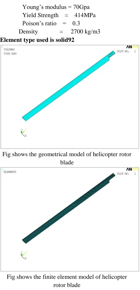
Young’s modulus = 70Gpa Yield Strength = 414MPa Poison’s ratio = 0.3 Density = 2700 kg/m3
Element type used is solid92
Fig shows the geometrical model of helicopter rotor blade
Fig shows the finite element model of helicopter rotor blade
Static analysis of helicopter rotor blade:
Structural static analysis has been performed on the helicopter rotor blade structure by applying the angular velocity and gravity of earth. The bolting locations are fixed in all Dof.
Gravitational force = 9810mm/s Angular velocity (Ѡ) = 15
Consider helicopter rotor blade maximum Angular velocity,
Ѡ=𝑣 𝑟
Available online:
https://edupediapublications.org/journals/index.php/IJR/
P a g e | 2133
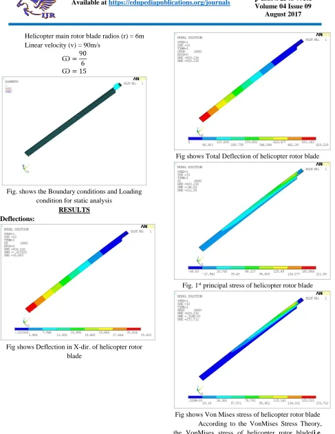
Helicopter main rotor blade radios (r) = 6m Linear velocity (v) = 90m/s
Ѡ=90 6
Ѡ= 15
Fig. shows the Boundary conditions and Loading condition for static analysis
RESULTS Deflections:
Fig shows Deflection in X-dir. of helicopter rotor blade
Fig shows Total Deflection of helicopter rotor blade
Fig. 1st principal stress of helicopter rotor blade
Available online:
https://edupediapublications.org/journals/index.php/IJR/
P a g e | 2134
alloy). Hence the design of helicopter rotor blade is safe for the above operating loading conditions.
Modal analysis of the rotor blade:
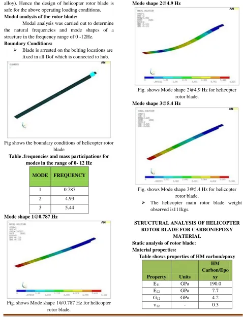
Modal analysis was carried out to determine the natural frequencies and mode shapes of a structure in the frequency range of 0 -12Hz.
Boundary Conditions:
Blade is arrested on the bolting locations are fixed in all Dof which is connected to hub.
Fig shows the boundary conditions of helicopter rotor blade
Table .frequencies and mass participations for modes in the range of 0- 12 Hz
MODE FREQUENCY
1 0.787
2 4.93
3 5.44
Mode shape [email protected] Hz
Fig. shows Mode shape [email protected] Hz for helicopter rotor blade.
Mode shape [email protected] Hz
Fig. shows Mode shape [email protected] Hz for helicopter rotor blade.
Mode shape [email protected] Hz
Fig. shows Mode shape [email protected] Hz for helicopter rotor blade.
The helicopter main rotor blade weight observed is111kgs.
STRUCTURAL ANALYSIS OF HELICOPTER ROTOR BLADE FOR CARBON/EPOXY
MATERIAL Static analysis of rotor blade: Material properties:
Table shows properties of HM carbon/epoxy
Property Units
HM Carbon/Epo
xy
E11 GPa 190.0
E22 GPa 7.7
G12 GPa 4.2
Available online:
https://edupediapublications.org/journals/index.php/IJR/
P a g e | 2135
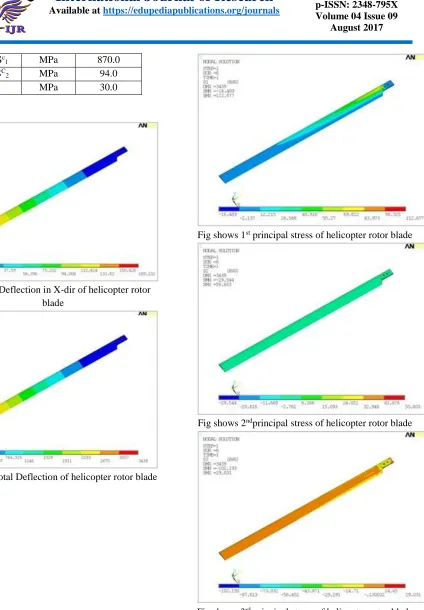
St
1= Sc1 MPa 870.0
St
2= SC2 MPa 94.0
S12 MPa 30.0
Results: Deflections:
Fig shows Deflection in X-dir of helicopter rotor blade
Fig shows Total Deflection of helicopter rotor blade
Stress:
Fig shows 1st principal stress of helicopter rotor blade
Fig shows 2ndprincipal stress of helicopter rotor blade
Fig shows 3rd principal stress of helicopter rotor blade
Available online:
https://edupediapublications.org/journals/index.php/IJR/
P a g e | 2136
29MPa are less than the principal stresses values of the material 870MPa, 54MPa, and 30MPa with respectively 1st, 2nd and 3rd principal stresses. Hence
according to the Maximum Stress Theory, the Composite Helicopter rotor blade design is safe for the above operating loads
Modal analysis of rotor blade:
Modal analysis was carried out to determine the natural frequencies and mode shapes of a structure in the frequency range of 0 -12Hz.
Results:
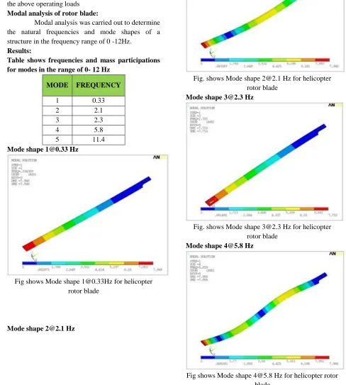
Table shows frequencies and mass participations for modes in the range of 0- 12 Hz
MODE FREQUENCY
1 0.33
2 2.1
3 2.3
4 5.8
5 11.4
Mode shape [email protected] Hz
Fig shows Mode shape [email protected] for helicopter rotor blade
Mode shape [email protected] Hz
Fig. shows Mode shape [email protected] Hz for helicopter rotor blade
Mode shape [email protected] Hz
Fig. shows Mode shape [email protected] Hz for helicopter rotor blade
Mode shape [email protected] Hz
Available online:
https://edupediapublications.org/journals/index.php/IJR/
P a g e | 2137
Mode shape [email protected] Hz
Fig shows Mode shape [email protected] Hz for helicopter rotor blade
Total helicopter main rotor blade weight observed is 66kgs.
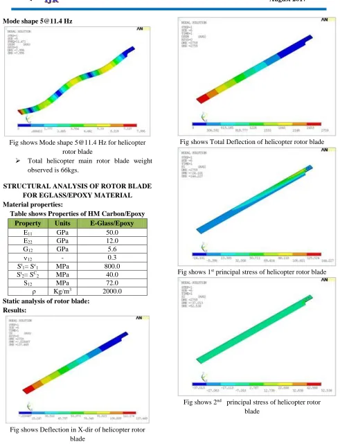
STRUCTURAL ANALYSIS OF ROTOR BLADE FOR EGLASS/EPOXY MATERIAL Material properties:
Table shows Properties of HM Carbon/Epoxy Property Units E-Glass/Epoxy
E11 GPa 50.0
E22 GPa 12.0
G12 GPa 5.6
12 - 0.3
St
1= Sc1 MPa 800.0
St
2= SC2 MPa 40.0
S12 MPa 72.0
ρ Kg/m3 2000.0 Static analysis of rotor blade:
Results:
Fig shows Deflection in X-dir of helicopter rotor blade
Fig shows Total Deflection of helicopter rotor blade
Fig shows 1st principal stress of helicopter rotor blade
Fig shows 2nd principal stress of helicopter rotor
Available online:
https://edupediapublications.org/journals/index.php/IJR/
P a g e | 2138
Fig shows 3rd principal stress of helicopter rotor blade
From the above results it is observed that the principal stresses values 144MPa, 52MPa, and 40MPa are less than the principal stresses values of the material 800MPa, 60MPa, and 74MPa with respectively 1st, 2nd and 3rd principal stresses. Hence
according to the Maximum Stress Theory, the Composite Helicopter rotor blade design is safe for the above operating loads.
Modal analysis of rotor blade:
Modal analysis was carried out to determine the natural frequencies and mode shapes of a structure in the frequency range of 0 -12Hz.
Results:
Table shows frequencies and mass participations for modes in the range of 0- 12 Hz
MODE FREQUENCY
1 0.37
2 2.3
3 2.6
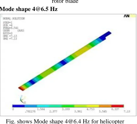
4 6.4
Natural frequencies and mode shapes are plotted below:
Mode shape [email protected]
Fig. shows Mode shape [email protected] for helicopter rotor blade
Mode shape [email protected] Hz
Fig. shows Mode shape [email protected] Hz for helicopter rotor blade
Available online:
https://edupediapublications.org/journals/index.php/IJR/
P a g e | 2139
Fig. shows Mode shape [email protected] Hz for helicopter rotor blade
Mode shape [email protected] Hz
Fig. shows Mode shape [email protected] Hz for helicopter rotor blade
Total helicopter main rotor blade weight observed is 82kgs.
RESULTS AND CONCLUSION
In the present project, the helicopter rotor blade was studied for structural analysis for different materials (aluminum and composite materials).
The helicopter rotor blade was studied for 3 different materials:
Aluminum HM carbon/ epoxy E-glass/ epoxy
CASE-1: Structural analysis of helicopter rotor blade with aluminum material:
From static analysis,
From the static analysis results it is observed that the maximum VonMises stress observed is 172 MPa. The maximum stress is observed on the bolting location. The yield strength of the material is 414 MPa.
From the modal analysis,
From the above modal analysis results it is observed that only 3 natural frequencies exists in the operating range of 0-12 Hz.
Total helicopter main rotor blade weight observed is 111kgs.
CASE-2: Structural analysis of helicopter rotor blade with HM carbon/ epoxy material:
From static analysis,
From the results it is observed that the principal stresses values 112MPa, 50MPa, and 29MPa are less than the principal stresses values of the material 870MPa, 54MPa, and 30MPa with respectively 1st, 2nd and 3rd principal stresses. From the modal analysis,
From the modal analysis results it is observed that only 5 natural frequencies exist in the operating range of 0-12 Hz.
Total helicopter main rotor blade weight observed is 66kgs.
CASE-3: Structural analysis of helicopter rotor blade with E-glass/ epoxy material:
From static analysis,
From the results it is observed that the principal stresses values 144MPa, 52MPa, and 40MPa are less than the principal stresses values of the material 800MPa, 60MPa, and 74MPa with respectively 1st, 2nd and 3rd principal stresses. From the modal analysis,
From the modal analysis results it is observed that only 4 natural frequencies exist in the operating range of 0-12 Hz.
The total weight of the rotor blade is 82 kgs.
Comparison of aluminum alloy, HM carbon/Epoxy and E glass/ Epoxy materials
Material FOS Weight
Aluminium alloy 414/172=2.4 111 HM carbon/Epoxy 870/167=5.2 66
E glass/ Epoxy 800/144=5.5 82 Hence the design of helicopter rotor blade is safe for the above operating loading conditions in all 3 materials.
Conclusion:
In the present project, the helicopter rotor blade was studied for structural analysis for different materials (aluminum and composite materials).
Available online:
https://edupediapublications.org/journals/index.php/IJR/
P a g e | 2140
software for different materials (aluminum alloy and composite materials).
From the above analysis it is concluded that the helicopter rotor blade has stresses and deflections within the design limits for the all three materials (aluminum and composite materials). From the results we can conclude that the HM carbon/ epoxy material helicopter blade has less weight and better stiffness and better factor of safety compare to other materials. Hence, it was concluded that the HM Carbon/Epoxy is best material.
REFERENCES
[1] The Dynamic Characteristics Analysis of Rotor Blade Based on ANSYS by Nian-zhao Jiang, Xiang-lin Ma, Zhi-qing Zhang.
[2] Design fabrication and testing of the helicopter tail rotor blade from composite laminated materials by boskorasuo,
[3] Structural analysis of the main rotor blade for a light helicopter - case of hovering flight mode by dianacazangiu, in may 2014,
[4] Performance optimization of helicopter rotor blades by Joanne L. Walsh
[5] Actuator design for the active trailing edge of a helicopter rotor blade by Christoph K. Maucher1, Boris A. Grohmann1, Peter Jänker1, Andree Altmikus2, Flemming Jensen3, Horst Baier.
[6] Srinivasan, G. R., and McCroskey, W. J., “Navier-Stokes Calculations of Hovering Rotor Flowfields,” Journalof Aircraft, Vol.25, No.10, 1988,pp865-874.
[7] Bell Helicopter TEXTRON. OH-58D Air Vehicle Technical Description Data; report no.406-099-026; Fort Worth, TX, May 1984. [8] Bell Helicopter TEXTRON. Model 406