Western University Western University
Scholarship@Western
Scholarship@Western
Electronic Thesis and Dissertation Repository
2-2-2015 12:00 AM
Rotor Position Identification for Brushless DC motor
Rotor Position Identification for Brushless DC motor
Muhammad Ikhlas
The University of Western Ontario Supervisor
Dr. Lyndon J. Brown
The University of Western Ontario
Graduate Program in Electrical and Computer Engineering
A thesis submitted in partial fulfillment of the requirements for the degree in Master of Engineering Science
© Muhammad Ikhlas 2015
Follow this and additional works at: https://ir.lib.uwo.ca/etd Part of the Controls and Control Theory Commons
Recommended Citation Recommended Citation
Ikhlas, Muhammad, "Rotor Position Identification for Brushless DC motor" (2015). Electronic Thesis and Dissertation Repository. 2676.
https://ir.lib.uwo.ca/etd/2676
This Dissertation/Thesis is brought to you for free and open access by Scholarship@Western. It has been accepted for inclusion in Electronic Thesis and Dissertation Repository by an authorized administrator of
ROTOR POSITION IDENTIFICATIN FOR BRUSHLESS DC MOTORS
(Thesis format: Monograph)
by
Muhammad Ikhlas
Graduate Program in Electrical and Computer Engineering
A thesis submitted in partial fulfillment
of the requirements for the degree of
Masters of Engineering Science
The School of Graduate and Postdoctoral Studies
The University of Western Ontario
London, Ontario, Canada
c
Abstract
Permanent magnet BLDC motors are characterized by a central magnetic core, called the rotor, and fixed electric coils (usually six) equally spaced in a ring around the core, called the stator. Motor movement is controlled by alternately energizing and de-energizing the stator coils to create a rotating magnetic field that propels the rotor. In order for this process to work correctly, BLDC motors required a technology called electronic commutation, in which the coil currents must be very carefully synchronized to rotor position to ensure that the rotating field is correctly aligned with the permanent magnetic field in the rotor. Usually rotor position is measured by external sensors such as Hall-effect sensors and optical encoders and these external sensors increase the system cost and reduces reliability. In order to control the price and make it more reliable this thesis propose to infer the rotor position from voltage and current measurement of motor.
The most common approaches to sensorless control are based on the measurement of the electromotive force (back-EMF), that is induced by the rotor motion. As the back-EMF is nearly zero at very low speed and at stationary position, and can not be measured. Therefore a separate algorithm is required for start-up and control at low speed. The other method of sensorless control involves the inference of rotor position from the variation in inductance caused by rotor position. This thesis presents a prototype system for sensorless control of BLDC motors over the entire speed range of the motor, including stall (zero speed) conditions using the voltage and current signals from the motor.
Keywords: Rotor Position, Sensorless Control of BLDC motor, Rotor Position identifi-cation, BLDC motor position
Acknowledgment
I would like to express my deepest appreciation and gratitude to my Supervisor, Dr. Lyndon J. Brown, Assistant Professor, Department of Electrical and Computer Engineering, Western University, for his support, advice, guidance and encouragement throughout my study du-ration and research work. It has been an honor for me to work under a mentor with such graciousness.
I acknowledge the support of technicians in the Engineering workshop and my lab mates for their great help during my work.
I would like to thank for the love, moral support and encouragement from my family and friends throughout my life. From you, I will always find an unwavering source of support to strive forward.
Above all, I would like to thank ALLAH Almighty for having given me the courage, patience, and the intellectual power to overcome all difficulties that I have faced during my graduate studies.
Contents
Abstract ii
List of Figures viii
List of Tables xi
List of Appendices xii
List of Acronyms xiii
List of Symbols xiv
1 Introduction 1
1.1 Introduction . . . 1
1.2 Background . . . 2
1.3 Comparison between Brushed and Brushless motors . . . 3
1.4 Comparison between BLDC and SRM . . . 5
1.5 Structural Review . . . 5
1.5.1 BLDC motor structure . . . 7
1.5.1.1 Electrical and Mechanical Angles . . . 8
1.5.1.2 Rotor Structure . . . 9
1.5.1.3 Stator Structure . . . 9
1.5.2 Switched Reluctance Motors (SRM) Structural Review . . . 10
1.7 Problem Statement . . . 13
1.7.1 Proposed Work . . . 14
1.8 Thesis Organization . . . 14
2 Literature Review 15 2.1 Introduction . . . 15
2.2 Principle of operation of BLDC motor . . . 16
2.2.1 Faraday’s Law . . . 17
2.2.2 Ampere’s Law . . . 17
2.2.3 Lenz’s Law . . . 18
2.3 BLDC Control Review . . . 18
2.3.1 Six step Commutation . . . 19
2.3.2 Sinusoidal Commutation . . . 21
2.3.3 Field Oriented Control . . . 23
2.3.4 Direct Torque Control . . . 25
2.4 Rotor Position Estimation . . . 27
2.4.1 Sensored Approach . . . 27
2.4.1.1 Hall Effect Sensors . . . 28
2.4.1.2 Variable reluctance (VR) sensors . . . 29
2.4.1.3 Optical Encoders (Magnetic Encoders) . . . 30
2.4.2 Sensorless Approach . . . 31
2.4.2.1 Back-EMF Sensing Techniques . . . 31
2.4.2.2 Inductance Variation . . . 34
2.4.2.3 Extended Kalman Filter . . . 34
2.4.2.4 Sliding Mode Observer . . . 36
2.5 Switched Reluctance Motor Control Review . . . 36
2.5.1 Principle of Operation of SRM . . . 37
2.5.2 Sensorless Control of SRM . . . 38
2.6 Summary . . . 40
3 Modeling of BLDC motor 41 3.1 Introduction . . . 41
3.2 Magnetic model . . . 42
3.2.1 Basic concepts . . . 42
3.2.2 Magnetic Materials . . . 43
3.2.3 BLDC Magnetic Model with Equivalent Electrical Circuit . . . 43
3.3 Electrical Model . . . 45
3.3.1 Flux Linkage . . . 46
3.3.2 Per Phase Electrical Model . . . 47
3.4 Mathematical Model . . . 49
3.5 Torque in BLDC . . . 50
3.5.1 Ideal Torque . . . 51
3.5.2 Torque Ripple . . . 51
3.5.3 Torque and Multiple pole pairs in BLDC Motors . . . 52
3.6 Back-EMF in BLDC . . . 53
3.7 General Electro-Mechanical Model . . . 54
3.8 Summary . . . 55
4 Measurements and Analysis 56 4.1 Introduction . . . 56
4.2 Inductance measurements . . . 56
4.2.1 Variable Inductance . . . 57
4.2.2 Inductance Readings using LCR meter . . . 58
4.3 Voltage measurement . . . 59
4.3.1 Measured Voltage . . . 60
4.3.2 Filtered Voltages . . . 62
4.4.1 Hall-Effect based Current Sensor Readings . . . 64
4.4.2 Filtered Current . . . 65
4.5 Inductance from Voltage and Current Signals . . . 66
4.5.1 Wye-Configuration . . . 67
4.5.1.1 Conclusion . . . 69
4.5.1.2 Wye Configuration With with back-EMF . . . 70
4.5.2 Delta Configuration . . . 71
4.5.2.1 Frequency Domain Analysis . . . 71
4.5.2.2 Delta Model For Inductance Information . . . 72
4.5.2.3 Conclusion . . . 75
4.6 Electrical Time constant Analysis . . . 77
4.6.1 BLDC motor Analysis . . . 77
4.6.1.1 At Maximum Inductance . . . 78
4.6.1.2 At Minimum Inductance . . . 78
4.6.1.3 Comparison of Voltages and Currents at two positions . . . 79
4.7 Summary . . . 81
5 Conclusion 83 5.1 Summary . . . 83
5.2 Problems Faced . . . 85
5.3 Future Work . . . 85
Bibliography 88
A Torque for Multiple Pole-Pairs 95
B Inductance Variation of BLDC motor 98
Curriculum Vitae 103
List of Figures
1.1 Comparison between Radial and Axial Flux motors . . . 6
1.2 Comparison between Inner Rotor and Outer Rotor motors . . . 7
1.3 Three phase BLDC motor with circuit diagram . . . 8
1.4 4-pole and 8-pole permanent magnet rotor . . . 10
1.5 slotted and slotless stator motors . . . 11
1.6 One phase cross-section of 8/6 SR machine . . . 12
2.1 Block diagram of basic BLDC motor system . . . 17
2.2 Six Step Commutation, Microcontrollers Sol Inc. . . 19
2.3 BLDC motor with six transistors power bridge . . . 20
2.4 Sinusoidal commutation with Hall sensor output . . . 21
2.5 Comparison between Six-step and sinusoidal commutation . . . 22
2.6 Direct (d) and Orthogonal (q) components . . . 23
2.7 Clarke’s transformation . . . 24
2.8 Park’s transformation . . . 25
2.9 Block diagram of generic FOC control drive . . . 25
2.10 Inverter voltage vectors and stator flux vectors . . . 26
2.11 3-phase Hall sensor chart with 120degree angle separation . . . 28
2.12 Variable Reluctance sensor . . . 29
2.13 Single ended Optical encoder . . . 30
2.14 Back-EMF zero crossing detection circuit model with PWM On-time . . . 32
2.15 Zero crossing points of the back-EMF . . . 33 2.16 Block diagram for EKF system for rotor and speed estimation of a BLDC motor 35
2.17 Aligned and Unaligned positions in SRM . . . 37
2.18 Per phase self inductance curve for SRM . . . 39
3.1 Cross sectional view of inner roto motor . . . 45
3.2 magnetic circuit of simple BLDC motor . . . 46
3.3 Simplified magnetic circuit of simple BLDC motor . . . 46
3.4 Simplified Electrical Model of BLDC motor . . . 48
3.5 Sinusoidal and Trapezoidal torque . . . 51
3.6 Ideal Torque and Current Shape for BLDC motor . . . 52
3.7 Sinusoidal and Trapezoidal Back-EMF of the motor . . . 54
3.8 Electro-Mechanical model of BLDC motor . . . 54
4.1 BLDC Motor Under testing . . . 57
4.2 Closed look of magnets for motor under testing . . . 58
4.3 Measured Inductance of 1 phase . . . 59
4.4 Measured Inductance of all three phases . . . 59
4.5 Dotted Points Showing reading of all three phases for 0o−90o . . . . 60
4.6 Lab setup to measure the Voltage and Current . . . 61
4.7 1 Phase to PhaseVoltage of Motor . . . 62
4.8 Two Phase to Phase Voltages of Motor . . . 62
4.9 Pulses generated by PWM in Voltage signal . . . 63
4.10 Filtered Voltages . . . 64
4.11 Two Phase Currents . . . 65
4.12 Noise in Current and its Filtered wave . . . 66
4.13 Raw Voltage data with External Voltage Present . . . 67
4.14 Raw Voltage data with no External Voltage . . . 67
4.15 Wye model for our setup . . . 68
4.16 Current Mean Values and Slopes with no Voltage . . . 69
4.18 FFT of window for Current of Phase A . . . 71
4.19 FFT of window for Current of Phase B . . . 72
4.20 FFT of a window for Phase AB Voltage . . . 72
4.21 FFT of a window for Phase BC Voltage . . . 73
4.22 Delta Configuration for Pure Resistive case . . . 73
4.23 Inductance Variation for Phase A . . . 74
4.24 Inductance Variation for Phase B . . . 74
4.25 Inductance Variation for Phase C . . . 75
4.26 Resistance Variation for Phase A . . . 75
4.27 Resistance Variation for Phase B . . . 76
4.28 Resistance Variation for Phase C . . . 76
4.29 Lab Setup for Step Input Response . . . 78
4.30 2 Phase to Phase Voltages for Both Tests . . . 79
4.31 Current A Response for Both Tests . . . 80
4.32 Current B Responses for Both Tests . . . 80
4.33 Comparison of Phase A Current . . . 81
4.34 Comparison of Phase B Current . . . 82
4.35 Comparison of Phase C Current . . . 82
5.1 tan Inverse of Slop and Mean values of Current . . . 86
List of Tables
1.1 Comparison Between Brushed and Brushless Motors . . . 4
List of Appendices
Appendix A Torque for Multiple Pole-Pairs . . . 95 Appendix B Inductance Variation of BLDC motor . . . 98
List of Acronyms
ADC: Analogue to digital convertor AFPM: Axial flux permanent magnet APFM: Axial flux permanent magnet BACM: Brushless AC motor
BDCM: Brushless DC motor
BLDC: Brushless direct current motor BLSM: Brushless servo motor
DTC: Direct torque control
ECBM: Electronically commuted brushless motor ECDCM: Electronically commuted DC motor EMF: Electromotive force
FOC: Field oriented control FFT: Fast Fourier transform MMF: Magnetomotive force
PMBDC: Permanent magnet brushless DC motor PMSM: Permanent magnet synchronous motor PWM: Pulse width modulation
RPM: Revolutions per minute SMO: Sliding mode observer
SPMSM: Surface PM synchronous motor SRM: Switched reluctance motor
List of Symbols
ε: EMF induced (V)
φ: Flux (Wb)
B: Magnetic field density (Wb/m2)
Bs: Stator magnetic field (Wb/m2)
Br: Permanent magnets field in rotor (Wb/m2)
H: Magnetic field strength (A/m) T: Torque (N.m)
ψ: Flux linkage (Wb(.turn))
µo: Permeability of free space (H/m)
µr: Permeability of material relative to free space (H/m)
λs: Stator flux linkage (Wb(.turn))
ω: Angular frequency
θe: Electrical angle (rad)
θm: Mechanical angle (rad)
θr: Rotor angle (rad)
dq: d-q coordinates
αβ: αβcoordinates
Chapter 1
Introduction
1.1
Introduction
The basic purpose of motors are to convert electrical energy to mechanical energy. Looking at the world around us and considering the importance of devices which uses this mecha-nism, we cannot just simply neglect the electrical motors and their working. Brushless DC motors also known as Permanent Magnet direct current Synchronous motors are becoming very popular and useful because of their high power density (the amount of power per unit volume), long life, high efficiency and reliable operation. Brushless DC motors as opposed to brushed DC motors do not require any mechanical brushes for its commutation system. Removal of brushes for commutation reduces the electric spark which results in reduction of the Electromagnetic interference(EMI). Initially, Brushless DC (BLDC) motors were mostly used in high-end military applications but due to the high efficiency and long life these motors became more common in daily life applications. Recently, these motors are well preferred in many electrical equipments which includes both high-end military applications and low price household appliances and toys. The main reason for their widespread applications be-coming reality after recent reduction in cost of these motors. Ideally, BLDC motors can be used any area where traditional motors (Brushed and induction motors) are being used as consumers now demands for the lower energy costs, better performance and reduced acoustic
Chapter1. Introduction 2
noise which cannot be achieved using the traditional technologies.
A typical BLDC motor consist of permanent magnets in rotor, and fixed electric coils equally spaced in stator. As the rotor magnets (rare-earth magnets) which are used in BLDC motors typically have high magnetic flux density and high electrical conductance making rotor losses small which results in the higher efficiency.
1.2
Background
Historically, the electric motors were described in three categories: 1) Brushed Commutator DC motors, 2) Synchronous motors and 3)Induction motors. From start the variable speed machines were desirable but this was not possible with the synchronous machines. With time as the desire of variable speed machines has progressed, so did the types of the machines. There were many variations of machines which were developed and one of these variations is Brushless Permanent Magnet machine. There were many steps and paths included in the development of these machines as mentioned by Jahns [1]. Initially a line-start permanent magnet machine was introduced and later in addition to that an electronically commutated (brushless) permanent magnet machine was devised. With more advancements in machine designs, eventually the concept of sinusoidal permanent magnet machine was introduced in combination with the inverter to provide an adjustable speed machine without brushes which can give servo like performance.
Chapter1. Introduction 3
There are number of Acronyms associated with Brushless DC motors. A few of them are mentioned below:
• BACM: brushless AC motor
• BDCM: brushless DC motor
• BLSM: brushless servo motor
• ECBM: electronically commuted brushless motor
• ECDCM: electronically commuted DC motor
• PMBDC: permanent magnet brushless DC motor
• PMSM: permanent magnet synchronous motor
• SPMSM: surface PM synchronous motor
Although there is inconsistency in literature for specifying the name of motors but in this thesis we will use BLDC motor (brushless DC motor) for trapezoidal back-EMF and PMSM (permanent magnet synchronous motor) for sinusoidal back-EMF.
1.3
Comparison between Brushed and Brushless motors
Chapter1. Introduction 4
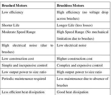
Table 1.1: Comparison Between Brushed and Brushless Motors
Brushed Motors Brushless Motors
Low efficiency High efficiency (no voltage drop across brushes)
Shorter Life Longer Life (less losses)
Moderate Speed Range High Speed Range (No mechanical limitation due to brushes)
High electrical noise (due to brushes)
Low electrical noise Low construction cost Higher construction cost Simple and inexpensive control Complex and expensive control Low output power to size ratio High output power to size ratio Periodic maintenance required Less maintenance due to absence of
brushes
Chapter1. Introduction 5
1.4
Comparison between BLDC and SRM
Switched reluctance motor (SRM) is a type of motor which is different from Brushless DC motor in torque production mechanism. In the case of BLDC motors, torque is produced by interaction of magnetic flux of windings and permanent magnets, whereas the SRM works on the principle of variable reluctance [2]. These motors generate torque without any permanent magnets and with no concentrated windings on their shaft. The SRM drive system first be-came available in early 1980’s as a result of work done in Leeds and Nottingham universities [3] - [4]. The main difference between a BLDC motor and SRM motor is the assemblies of rotor and stator and the materials used. SRM motors also need the sensors and an electronic commutation controller similar to BLDC motors. The main advantages of using SRM are given below:
1. SRM is inexpensive to manufacture as it is made up of simple laminated steel and has no rotor windings.
2. As there are no rotor windings in SRM, they mainly get heated up in stator where the machine is easily cooled.
3. SRM can work on high speed in intense environments because of their simplicity and ruggedness.
4. The SRM requires unipolar currents only, allowing the design of an inexpensive con-verter with one controllable power switch per phase.
1.5
Structural Review
Chapter1. Introduction 6
theRotor. There are basically two configurations of DC motors on basis of the structure of stator and rotor.
1. Axial Flux 2. Radial Flux
Axial flux motors [5] are also an active area of research but these type of motors are not that common in servo application as compared to radial flux motors. These type of motors have special applications such as floppy disk spindle drives. The primary reason for less use of these motors is the stator construction. As the flux flows axially in these motors, the stator must by laminated circumferentially. This construction orients slots at ever increasing distances from one another. As a result, this significantly increases stator manufacturing time and cost. The Axial flux motors are further divided into single sided AFPM machines and double sided AFPM machines [5]. The difference between radial and axial flux motors is explained in Figure 1.1
Figure 1.1: Comparison between Radial and Axial Flux motors
Chapter1. Introduction 7
desired in constant speed applications. Although for outer rotor motors, individual magnets can be used but the more common practice is to use a single bonded magnet ring inside the rotor. This motor is also easy to wind as the teeth of the stator points outward. The main difference between inner and outer rotor motors is explained in Figure 1.2
Figure 1.2: Comparison between Inner Rotor and Outer Rotor motors [6]
1.5.1
BLDC motor structure
All of the electrical and mechanical issues because of the brushes with the brushed tech-nology are eliminated in brushless DC motors. In BLDC motors the brushes are replaced with an electronic controller which control the speed of the motors. The current carrying coils/winding are stationary and energized sequentially to cause the Permanent Magnet rotor to turn. BLDC motor is usually constructed in single-phase, two-phase and three phase con-figurations, where the three phase configuration is the most commonly available for BLDC motors. BLDC motors with more than three phases can also be manufactured but they are not common and they hugely increases the manufacturing cost [7]. A typical three phase BLDC motor with its circuit diagram is shown in Figure 1.3.
Chapter1. Introduction 8
Figure 1.3: Three phase BLDC motor with circuit diagram
phases and a negative current to another while leaving no current going into the third phase. The interaction between the field generated in the stator due to current and by the permanent magnets on the rotor, generates the torque in the motor and as a result the motor starts to rotate. To keep the motor rotating, the current in the stator which generate the magnetic field needs to be commutated in a specific pattern. This current commutation is controlled and switched in specific commutation steps for each electrical rotation.
1.5.1.1 Electrical and Mechanical Angles
Chapter1. Introduction 9
the main role in determining the relationship between electrical and mechanical positions of the motor. For a motor which has single pole pair, the electrical and mechanical revolution are equal and hence the electrical and mechanical angle are also equal. But in case of more then one pole pair, the number of electrical and mechanical revolutions are not equal and hence their angles. The relationship between the electrical angle and mechanical angle can be expressed using Equation 1.1, which shows that as the number of pole pairs increases the electrical revolutions in one mechanical revolution also increases.
Polepairs= Electrical angle
Mechanical angle (1.1)
1.5.1.2 Rotor Structure
Generally, permanent magnets are used to build the Rotor of a brushless DC motor. The num-ber of magnets in the rotor defines the numnum-ber of rotor poles. Depending on the requirements, we can have BLDC motor with different number of poles. By increasing the number of poles in the rotor we can increase the torque but it reduces the maximum speed of the motor. The greater number of magnet poles does generate greater torque but more magnet poles implies having less room for each pole. Eventually the maximum point is reached where the gap between rotor magnet poles becomes significant percentage of the total space on the rotor, and the torque no longer increases. The optimum number of magnetic poles mainly depends on the motor geometry and the material properties which is being used in the motor. The torque generated depends on the material used for the construction of the permanent magnet as the torque depends on the flux density of the material. The higher the flux density of ma-terial used the higher the torque generated. 4-poles and 8-poles rotors are shown in Figure 1.4
1.5.1.3 Stator Structure
Chapter1. Introduction 10
Figure 1.4: 4-pole and 8-pole permanent magnet rotor [8]
Windings in the stator can be arranged in both star and delta pattern. The star configuration at low RPM gives high torque while the delta configuration gives low torque at low RPM. Each winding is constructed with numerous coils interconnected with each other and these windings are distributed over the stator to generate the required number of poles. We can also divide BLDC motors in two types according to the stator windings variant i.e. trapezoidal motors and sinusoidal motors. This difference is created on the basis of the interconnection of the coils in the windings to give different type of back EMF. Sinusoidal motors are smooth rotating motors which make them popular for applications which require quiet operation and low vibration but these type of motors need additional cost of windings and also the compli-cated algorithm to control. The lamination in stator can be slotted or slotless as shown in the Figure 1.5. A slotted core has high inductance which reduces the speed range of the BLDC motor. Therefore slotless core is more suitable for high speed requirements but they increase the cost as slotless core needs more winding to compensate for the air gap.
1.5.2
Switched Reluctance Motors (SRM) Structural Review
Chapter1. Introduction 11
Figure 1.5: slotted and slotless stator motors [9]
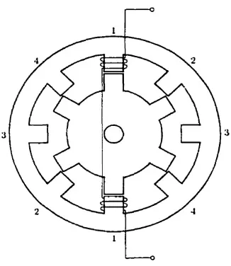
has a simple concentrated winding and there are no conductors of any type on the rotor. These simple windings on the stator pole are connected in diametrically opposite pairs and are independently connected to a remote switching circuit for its commutation. Commonly, the rotor and stator are assembled from steel lamination of the same grade and thickness. The construction of SRM is very simple, reliable and rugged which gives it few advantages over the conventional brushless machines [10]. A cross-sectional overview of a typical 8 stator and 6 rotor poles machine is shown in Figure 1.6.
Chapter1. Introduction 12
Figure 1.6: One phase cross-section of 8/6 SR machine
1.6
Typical Applications of BLDC
Regardless of the need of a complex motor controller for BLDC motors, BLDC motors offers several inherent advantages which are not available by using brushed DC motors in terms of high torque and wide speed range. Better heat dissipation, improved efficiency and greater power density for BLDC motors make them more suitable and advantageous in many applica-tions. The research presented in [11] -[12] shows that the permanent magnet machines could become more important than induction motors for servo applications. The major applications for BLDC motors are given below:
1. Battery Powered Applications
(a) Electric and Hybrid vehicles (b) Electric scooters and bicycles (c) Low Voltage Drives
2. Home and Building Applications
Chapter1. Introduction 13
(b) Fans in cooker hoods (c) Washing machines
(d) Air Conditioners and refrigerators [13] 3. Industrial Applications
BLDC motors are primarily usefull in actuation, servo and variable speed applications where position control and stable operations are required. BLDC motors are commonly used as:
(a) Linear motors (b) Servomotors
(c) Extruder drive motors
(d) Actuators for industrial robots
(e) Automotive HVAC(Heating Venting and Air-Conditioning)
1.7
Problem Statement
Chapter1. Introduction 14
1.7.1
Proposed Work
Keeping the cost and durability of BLDC motors in mind this thesis propose to infer the rotor position of the motor from voltage and current signal measurements by solving these voltage and current signals to find the inductance of each phase. This inference of rotor position can be used to generate a proper sequence for commutation of motor.
1.8
Thesis Organization
The thesis is organized in the following manner.
Chapter 1provides a basic introduction of Brushless Direct Current Motors (BLDC motors).
Chapter 2 gives the detailed background of BLDC motor control in two portions covering both sensored control and sensorless control. Also some aspect of Switched Reluctance mo-tors control are described.
Chapter 3presents the BLDC model for one phase covering its both magnetic part and elec-tric part along with the description of mathematical model. At the end of the chapter the motor part is combined with the mechanical part and explains the three phase model.
Chapter 4 deals with the experimental work and the analysis of the data obtained from the experiments. It also covers the results obtained for both delta and wye models.
Chapter 2
Literature Review
2.1
Introduction
The Brushless DC motor has become very important in most of the small-scale electric ve-hicles from low performance application to high end applications [14]. The BLDC motor is inherently efficient, has a very high power to weight ratio and the removal of brushes makes them best choice for such applications. However the current state of electrical controllers available in industry restricts these motors capabilities and offer only limited controllability. This performance issue related to commercial controllers available in industry is basically because of the simple control techniques that are invariably used. Most of the controller use six step control strategy which results in poor dynamic performance of the motor and high torque ripple leading to greater vibrations and shorter motor life. Also these controllers are not capable of working on low speed range and limit the performance of the BLDC motors. This chapter explains the motor structure and the existing control algorithms used in industry. To begin with, the basic principle of operation of BLDC motor is presented. This section also covers the torque and back emf generation and the similarities and differences between three-phase sinusoidal and trapezoidal motors. The second section describes the BLDC mo-tor control technologies covering both the sensored and sensorless approach. A few of the
Chapter2. LiteratureReview 16
major approaches adopted are discussed for both sensored and sensorless control for motor drives. The third section covers the main part of the BLDC motor control i.e. the rotor posi-tion calculaposi-tion which is the most important step in most of the sensorless control methods. The last section of this chapter presents the overview of switched reluctance motors and the sensorless approach used to control the SR motors.
2.2
Principle of operation of BLDC motor
Chapter2. LiteratureReview 17
Figure 2.1: Block diagram of basic BLDC motor system and voltage induced in case of BLDC motors.
2.2.1
Faraday’s Law
Faraday’s law of induction was presented by Michael Faraday (1791-1867), which describes the voltage induced in a coil of wire in following two different forms:
1. “A moving conductor cutting the lines of force (flux) of a magnetic field has a voltage induced in it”.
2. “A changing magnetic flux inside a loop which is made from a conducting material will induce a voltage in the loop”.
Mathematically the Faraday’s law is explained in Equation 2.1 where ϕ represents the total flux through the loop of wire in a plane perpendicular to the flux andεrepresents the voltage induced.
ε= dϕ
dt (2.1)
2.2.2
Ampere’s Law
Chapter2. LiteratureReview 18
“The integral around a closed path of the component of the magnetic field tangent to the direction of the path equalsµotimes the current intercepted by the area within the path”.
Mathematically Ampere’s law is expressed as in Equation 2.2 below:
I
B.ds =µo.I (2.2)
Ampere’s law is very useful when magnetic field is calculated for a current distribution with a high degree of symmetry. Only the currents crossing the area inside the path are taken into account and only these currents contribute to the generation of magnetic field [15].
2.2.3
Lenz’s Law
Lenz’s law is named after Heinrich Lenz and it states that:
“An Induced voltage is produced by a change in magnetic flux. The polarity of the induced voltage is such that it produces a current whose magnetic field opposes the change which produces it”.
Mathematically it is expressed same as Faraday’s law but with the opposite sign as this voltage is induced in the opposite direction against the change which produces it.
ε=−dϕ
dt (2.3)
2.3
BLDC Control Review
Chapter2. LiteratureReview 19
to 90 degrees. Therefore, special controllers are required which control the voltage on the basis of rotor position detected. Once the rotor position is detected, the controller works appropriately to generate a proper commutation sequence of the voltage strokes so that the BLDC motor keep on rotating. The BLDC motor is supplied with the three-phase inverter and the commutation sequence can be simply used to trigger the switching actions of the inverter. There are different control techniques available in industry for brushless DC motors and are explained below.
2.3.1
Six step Commutation
The six step commutation also know as trapezoidal commutation is the simplest form of the commutation which is available in the market to control the BLDC motor. Figure 2.2 shows the six step commutation for brushless DC motors.
Chapter2. LiteratureReview 20
The trapezoidal commutation requires the digital Hall devices to detect the position of the rotor aligned 30 degree electrically from the zero crossing point of the phase. As soon the Hall signal transition takes place, the sequence is changed for the phase current, thus the commutation of the motor occurs and if this commutation keeps working, the BLDC motor will rotate continuously. The three-phases of the BLDC motor are energized in 120 degree sequences and each phase winding’s voltage is high for 120 degrees. The current is conducted through two of the three phase windings at anytime with one phase winding held at a high electrical potential and the other at low electrical potential. The third phase winding is kept off during this interval. This gives the six possible commutation steps per one complete revolution as shown in Figure 2.2 [13].
Figure 2.3 shows the BLDC motor with transistors bridge which generates the six-step com-mutation sequence shown in Figure 2.2 [13].
Figure 2.3: BLDC motor with six transistors power bridge
Chapter2. LiteratureReview 21
lifespan.
2.3.2
Sinusoidal Commutation
The ideal approach to drive the sinusoidal brushless motor is to use the sinusoidal commuta-tion technique. By using the sinusoidal commutacommuta-tion, the flat peaks of six-step commutacommuta-tion are replaced with sinusoids. There are two possible ways by which sinusoidal commutation is achieved. As analog Hall effect devices can generate a sinusoidal signal when the motor rotor passes over the sensor magnetic poles. The signals, which are correct for commutation of the motor are combined with the demand signals to generate the sinusoidal commutation for the motor. This method is the cheaper one of the two but using this method can generate more noise and affect the commutation sequence resulting in poor performance of the motor. Figure 2.4 shows the sinusoidal commutation with respect to the Hall sensor output.
Figure 2.4: Sinusoidal commutation with Hall sensor output [16]
Chapter2. LiteratureReview 22
of commutation gives the best result of the two approaches, but adding the encoders increases the overall cost of the motor. The commutation is done in the second approach by generat-ing a sin(θ) phase A command signal and 120 degrees shifted sin(θ+120) phase B command signal and multiplying this by the current command. The nature of the sinusoidal back-EMF needs the commutation phases to be overlapped and because of this overlap the torque ripple is reduced and more precise control of the motor is acvhieved. The comparison between six-step and sinusoidal commutaion is shown in Figure 2.5 [17].
Chapter2. LiteratureReview 23
2.3.3
Field Oriented Control
The Field Oriented Control (FOC) also called Vector Control for BLDC motors is a process to achieve torque control by controlling the space vectors of voltage and current directly in a new reference frame known as the d-q reference frame. In this process the flux linkage state vector is decomposed into two discrete components, the first component is flux(d) and the second component torque(q). During this process a three-phase system is transformed into a two co-ordinate (d-q) system. This transformation is computationally intense mathemat-ics as it demands a lot of computer based computation and simplification, and is known as Park’s and Clarke’s transformation. This method is computationally so complex that it needs high processing power DSPs, micro-controllers or FPGAs in controlling the motor. Figure 2.6 shows the graphical representation of the the d-q components. The q-d components are intrinsically orthogonal to each other [18].
Figure 2.6: Direct (d) and Orthogonal (q) components [19]
cur-Chapter2. LiteratureReview 24
rents and transforms it to a two-dimensional orthogonal variables mostly denoted byαandβ [20]. Figure 2.7 shows the graphical representation of the Clarkes transformation. Once the three phase system is transformed into two phase (α&β) stationary system, it is necessary to transform them into a system that is rotating along with the rotor flux. This step is done using Park’s transformation [21]. Figure 2.8 shows the graphical representation of the Park’s transformation. After Clark’s and Park’s transformations the stator current is now in two-phase system aligned with the rotor flux. The direct component does not provide any useful torque generation information and can be neglected. The quadrature component is mainly re-sponsible for the actual torque generation of the motor. These two components are processed and then converted back to stator referenced two-phase system to generate the pulse width modulation (PWM) to drive the motor appropriately.
Figure 2.7: Clarke’s transformation [20]
Chapter2. LiteratureReview 25
Figure 2.8: Park’s transformation [20]
Figure 2.9: Block diagram of generic FOC control drive [22]
2.3.4
Direct Torque Control
Chapter2. LiteratureReview 26
apply DTC method an estimator is needed to estimate the torque and flux of the stator. Along with an estimator, a look-up table and hysteresis comparators are also needed to complete the process [27]. In DTC method the stator currents and the DC-bus voltage are sampled at each interval and using the manufacturer provided data and these measured values of current and voltage for the stator resistance, the flux of stator is calculated inα-βreference frame. During DTC process the stator flux rotation is divided into six possible discrete inverter voltage vectors as explained in Figure 2.10.
Figure 2.10: Inverter voltage vectors and stator flux vectors [27]
Chapter2. LiteratureReview 27
motor drives. Unlike FOC, DTC method does not need any reference frame transformation and rotor position estimation which decreases the overall cost of the drives and also requires less development time. Cassadei [28] concluded that the DTC is preferred in high dynamic load applications but it results in a higher current and higher torque ripple comparing to FOC method.
Direct torque control method based on hysteresis controllers as mentioned above have some serious drawbacks such as larger amount of torque and flux pulsation and the variable frequency of the inverter. Also using DTC to control the BLDC motor needs a continuous observation on stator flux linkage and the accuracy of this observation is affected by stator resistance variation, electric and magnetic interfernce and measurement errors.
2.4
Rotor Position Estimation
The measurement/estimation of rotor position is the most critical step in controlling the BLDC motors. A small error in position estimation for BLDC motor can result in very poor performance and in some cases it may result in a complete motor failure. The estimation of the rotor position can be done by sensored and sensorless approaches. In sensored approach some type of external sensors are attached with the motor, while for sensorless there are no sensors attached to the motor itself.
2.4.1
Sensored Approach
Chapter2. LiteratureReview 28
2.4.1.1 Hall Effect Sensors
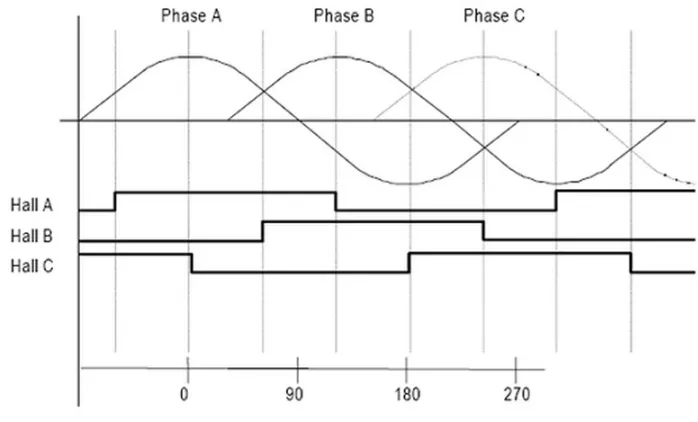
Hall Effect sensor is the most common sensor seen in rotating machines. Hall-effect theory states that “if an electric current carrying conductor is kept in magnetic field, the magnetic field exerts a transverse force on the moving charge carriers that tends to push them to one side of the conductor”. The presence of this transverse voltage is called the Hall-effect as it was first discovered by Edwin Hall in 1879. For rotor position estimation, mostly there are three hall effect sensors embedded into the stator. Whenever the rotor magnetic poles passes near these Hall-effect sensors they generate high or low signal showing the S or N poles of the rotor magnet. Hall sensors are embedded into the fixed part of the motor and this is done by a complex process as any misalignment in the sensors with respect to magnets in rotor will produce an error in the rotor position estimation.
Figure 2.11: 3-phase Hall sensor chart with 120degree angle separation [29]
Chapter2. LiteratureReview 29
wiring reduce the reliability of the motor. The classical three hall effect sensor configuration just estimate the position of the rotor to an accuracy of 60 degrees only. Therefore, using the simple classical approach we can only get the position of the rotor with less accuracy.
2.4.1.2 Variable reluctance (VR) sensors
The variable reluctance sensors are used to detect the position and speed of the moving metal components and are also referred as a passive magnetic sensor as it does not need any power for itself to detect the signal. The VR sensor consists of a winding wound around a cylindri-cal magnetic material made up of ferrous. A magnet is attached behind the pole piece which creates a magnetic field through pole and windings. When these sensors are placed near a moving device, a simple technique for measuring the speed is created. The frequency of the signal is directly proportional to the speed of the device. The amplitude of the signal de-pends on the speed of rotation, the material being sensed and the the distance of the material from the sensor. It is usually very simple to implement and the physics behind its operation includes magnetic induction [30]. A basic mechanism of how variable reluctance sensors works is explained in Figure 2.12.
Chapter2. LiteratureReview 30
The main advantage of using variable reluctance sensor is its low cost and simplicity. VR sensors are robust and can operate at higher temperature ranges and also these sensors are small in size so they can be embedded in places where other sensors may not fit. These sensors are resistant to high pressure and high temperature as well as chemical attacks [32]. These sensors need less wiring connections which enhance its reliability and reduces the wiring cost [31].
2.4.1.3 Optical Encoders (Magnetic Encoders)
The optical sensing technology is the most accurate and provide the highest resolution of the position estimation. As the name shows the optical encoders use light to identify the positions. The optical encoders consists of a light source, sensor, movable disk and a fixed mask. A photo detector is used in optical encoders to sense the alternating light beams and the encoder’s electronics convert this pattern into an electrical signal which is then processed to find how far from original position the disc has rotated. The Optical Shaft Encoder uses an infrared light sensor to detect illumination from an infrared LED passing through slots cut in the circumference of a rotating wheel. A single optical encoder is shown in Figure 2.13.
Figure 2.13: Single ended Optical encoder [33]
Chapter2. LiteratureReview 31
guidance. There are many different considerations when determining what type of encoders to use in a specific application. Choosing a right optical encoder for a particular application is not a difficult process but its always good to ensure all the different application criteria are considered before selecting a specific encoder [34].
2.4.2
Sensorless Approach
The problems associated with the cost and reliability of sensors used to detect the rotor po-sition have motivated research in the area of sensorless popo-sition detection for BLDC motor drives. In the last decade, many sensorless drive solution has been offered to eliminate the costly and fragile position sensors for BLDC motor. These solutions mainly depend on the back-EMF detection of the motor [13] - [35]. Many research efforts have been done for this area but none works well at all speeds without reliability, accuracy and complexity problems, especially at very low speed ranges. Therefore, mostly a separate starting algorithm is needed to start the BLDC drive and once a particular speed is achieved where back EMF is easily detected then the controller start working on the basis of back EMF detection. Also the po-sition error from a phase shift in transient state deteriorates the performance of the BLDC motor drive [13] - [36]. Below are the main sensorless approaches for controlling the BLDC motors.
2.4.2.1 Back-EMF Sensing Techniques
Chapter2. LiteratureReview 32
in current waveforms are shown in Figure 2.15. Since back-EMF is zero at stand still and low speed ranges, the measured terminal voltage cannot detect the zero crossing. The back-EMF zero crossing position estimation is more suited to two-phase conduction motors. The zero crossing can be found by feeding the voltage of the un-powered winding with respect to the virtual ground and half the DC bus voltage to comparator. At this state the compara-tor output changes showing that the zero crossing has occurred and the next sequence can be started [39]- [40]. Back-EMF zero crossing detection with winding flow is explained in Figure 2.14.
Figure 2.14: Back-EMF zero crossing detection circuit model with PWM On-time [39] For typical BLDC motor, the back-EMF and the phase current should be aligned to generate a constant torque. To generate the maximum torque, the inverter should be commutated every 60 degree by detecting the zero crossing of the back-EMF and the floating coil of the motor so that the current is in phase with the back-EMf of the motor [42] - [43].
phys-Chapter2. LiteratureReview 33
Figure 2.15: Zero crossing points of the back-EMF [41]
ical sensors to be mounted in or on the surface of the motor. There are also some drawbacks of using this sensorless approach for the position estimation as mentioned below:
1. The back-EMF is directly proportional to the speed of the motor. This means that there is no back-EMF when the rotor is at stationary state and also very low at low speed. Therefore, the back-EMF sensing approach is not applicable at all speed ranges and need a separate mechanism to control the BLDC motor at stand still and low speed ranges.
2. The back-EMF sensing method requires one phase to be non-current carrying in or-der to detect the back-EMF which means that only two phases are available for the conduction which results in the trapezoidal back-EMF which reduces the efficiency performance of the motors.
Chapter2. LiteratureReview 34
4. By using the back-EMF sensing approach, the rotor position of the BLDC motor can be detected typically from 20% of the rated speed [13].
2.4.2.2 Inductance Variation
One of the method of sensorless control that is at least theoretically possible, involves the inference of rotor position from the variation in inductance caused by rotor position. This effect has been exploited by Jang et al [44] to develop pulse-based start-up algorithms, in which the variable response times to current changes at different rotor positions are used to detect rotor position. In this approach the variation of inductance on the relative position of rotor and stator is utilized. Cassat et al.[45] detected the position of rotor at stand still by comparing the rise time of the currents due to the inductance variation after a current pulse was injected into all six segments of any electrical cycle. As compared to the conventional back-EMF, the method presented by Jang et al. [44] based on inductance calculation can drive the brushless DC motor to a normal speed smoothly without showing any time delay or vibration in startup.
2.4.2.3 Extended Kalman Filter
Chapter2. LiteratureReview 35
The extended Kalman filter approach can be used to determine the position and speed of the motor. In this method the motor state variables are estimated in both transient and steady states [49]. The block diagram for the EKF system used for the speed and position estimation for rotor in BLDC motor is shown in Figure 2.16 [47]. In this system the measured speed (ωk), phase currents (ik) and the estimated rotor position (ϑk/k) are used as a feedback
signals.The rest of the parameters are calculated and measured to find out the estimation of next state of the rotor position and speed.
Figure 2.16: Block diagram for EKF system for rotor and speed estimation of a BLDC motor [47]
Chapter2. LiteratureReview 36
2.4.2.4 Sliding Mode Observer
Sliding mode observer (SMO) is a special kind of a non-linear control of the motor which is different from the conventional control methods. The approaches discussed above for sen-sorless control are motor observers. In this approach a sliding motion is generated on the error between the output of the observer and the actual measured system output [50]. This sliding movement to move a system along a certain path to do small, high frequency upper and lower movement under certain conditions makes this method a variable structure control. There are different approaches being adopted to design a sliding mode observer. One of the approaches is based on the equivalent control technique in which the system equations are converted to two suitable sub-systems. An appropriate sliding plane is then selected and a full state observer for the reduced order is designed. The other approach is designing a full state observer instead of reduced order and then sliding mode techniques are applied to stabi-lize the resulting error system [51].
Using sliding mode observer method for controlling BLDC motor drives gives a good overall performance as it gives much accurate rotor position. Also by using the estimated values as a feedback in closed-loop control, the real speed response of motor drives can be enhanced. Many researches are undergoing on different methods for designing SMO for better performance. This goes to show the broad nature of SMO theory and the requirement of a significant design for the successful implementation of any observer [52].
2.5
Switched Reluctance Motor Control Review
Chapter2. LiteratureReview 37
2.5.1
Principle of Operation of SRM
SRM like BLDC machine is an energy converter which takes the energy from the magnetic fields created by the phase windings and exchange this energy between the electrical and me-chanical subsystems. In a magnetic circuit, analogous to resistance there exists a magnetic reluctance which depends on the magnetic permeability of the material which is used for magnetic structure. In SRM the reluctance in the air gap between the rotor and stator poles is very large as compared to the reluctance of the steel lamination used. Therefore, the reluc-tance of the SRM is mostly considered to be because of the air gap. SRM is a doubly salient machine and when it start rotating the distance between the rotor and stator poles changes resulting in the change in the reluctance. There are two main positions which are of great interests in SRM known as ”aligned position and unaligned position”. In Aligned position the rotor pole is exactly aligned with the stator pole of the phase and hence the reluctance is minimum at this position. When the rotor pole and the stator pole is exactly unaligned the reluctance is maximum and this is known as unaligned position of SRM. These two positions for SRM are shown in Figure 2.17.
Figure 2.17: Aligned and Unaligned positions in SRM
Chapter2. LiteratureReview 38
position as the reluctance is at its maximum and this position is also its equilibrium position but an unstable one. However, as soon as the rotor moves to any side of the equilibrium po-sition, a torque is generated and this torque displaces the rotor further and attracts it to the next equilibrium position. As the rotor poles are identical throughout, the torque generated in SRM is periodic. The period of this torque is called the rotor pole-pitch (τ) and given by Equation 2.4, where Nris the number of rotor poles.
τ= 2π
Nr
(2.4) If the phases of the SRM is energized successfully in a proper sequence, a continuous torque is produced. For this successful commutation, the rotor position of the motor is required similar to BLDC motors. As the inductance of the stator coil varies with the rotation of the rotor from its minimum to maximum value, the SRM commutation needs rotor position continuously. Therefore, the performance of the SRM also depends on the accuracy of the position detection method used. As we have discussed different methods to detect the rotor position for the BLDC motors, they can also be used for SRM as well. Some researches has been done on the different rotor position detection methods for SRM including optical encoders [55], impedance measurement approach [56] and rotor position estimation from stator voltage and currents [57].
2.5.2
Sensorless Control of SRM
Chapter2. LiteratureReview 39
2.5.2.1 Sensorless control of SRM using Phase Inductance
In switched reluctance motors the inductance of the stator phase and the slope of inductance for the same phase, changes periodically with the position of the rotor and also the instanta-neous current of the phase due to the magnetic saturation. The self inductance characteristic curves for SRM is shown in Figure 2.18. There have been many research efforts in the recent years on sensorless control of SRM on basis of the flux linkage and phase inductance [58]. Cai [58] presented a sensorless approach based on phase inductance of the SRM to control the motor. The phase inductance and flux linkage is related with each other according to Equation 2.5.
Figure 2.18: Per phase self inductance curve for SRM
L(i, θ)= ψ(θ,i)
i (2.5)
Chapter2. LiteratureReview 40
goes to zero in that situation and ultimately the inductance at that state can not be calculated. The approach taken by Cai is limited and less accurate as just using the inductance values of aligned and unaligned positions and set the value of the phase inductance to zero when current is decaying to zero in offstate. By doing so the method is simplified but it leads to the problems and error in estimation of the rotor position. Also his approach is suitable for high speed operation as at low speed the error in position estimation is a problem and he proposed to use pulse injection methods to start and run the motor at low speed.
2.6
Summary
Chapter 3
Modeling of BLDC motor
3.1
Introduction
As it is obvious that motors are used to convert electrical energy into mechanical energy. The brushless permanent magnet motor relies on the conversion of electrical energy to magnetic energy which is then converted into the mechanical energy. In this chapter the BLDC motor will be explained in individual parts i.e. Electrical part and magnetic part. In first section of the chapter we will discuss the magnetic model and flux linkage of the BLDC motors. In the second section of the chapter, we will look into the electrical model of the BLDC, also the per phase electrical circuit of the BLDC motors. In the third section of the chapter a brief mathematical model will be discussed and with the help of electrical, magnetic and mathematical models discussed, we will look into the torque and back emf generation for BLDC motors in the fourth section of the chapter. At the end of the chapter a general electro-mechanical model for motor will be discussed briefly.
Chapter3. Modeling ofBLDCmotor 42
3.2
Magnetic model
3.2.1
Basic concepts
There are two main sources of magnetic fields in BLDC motors, one being the permanent magnets and the other being a current flowing in windings. The magnetic field generated because of the current in stator windings is given by the Ampere’s law as explained in section 2.2. The magnetic field of the permanent magnets is generally described by Equation 3.1, where B is the flux density of the magnetic field flowing through a given area of the material,
µis the permeability of the material used and the field intensity H is the resulting change in the intensity of the magnetic field due to the interaction of flux density (B) with the material.
B= µH (3.1) Magnetic circuit analysis is generally based on the assumptions of the linearity of the material and the collinearity of flux density (B) and field intensity (H). The two fundamental equations which leads to the magnetic circuit analysis are given below. Equation 3.2 relates the flux density to flux, whereφis flux, A is the cross sectional area and B is the flux density. Equation 3.3 relates field intensity to electromotive force, where F shows the electromotive force and H is the field intensity.
φ= BA (3.2)
F = Hl (3.3)
Combining above two equation gives a relation which is analogous to Ohm’s law for electric circuits and is explained in Eqation 3.4 whereµis the permeability of the material.
F = φl
Chapter3. Modeling ofBLDCmotor 43
3.2.2
Magnetic Materials
The magnetic properties of the material is generally referred in term of the permeability of the material and commonly expressed with respect to the permeability of the free space as shown in Equation 3.5, whereµois the air permeability and has the value of 4π.10−7 (H/m).
µr=
µ µo
(3.5) Commonly the materials having the permeability close to one are called non-magnetic materials while the materials with very high permeability are known as magnetic materials. The most common material used in the construction of the motors is steel which has a non lin-ear permeability and that means the flux density through the material is not unique for a given field intensity. Recently different types of permanent magnet materials are available including alnico, ferrite, samarium-cobalt and neodymium-iron-boron. The ferrite type magnetic ma-terials are inexpensive and are preferred in motor constructions. On the other hand the rare earth type materials e.g. samarium-cobalt offer the highest performance but they are highly expensive materials. Each of these magnetic materials have different properties and leads to different constraints and performance levels in BLDC motors. Usually the magnets are compared by the maximum energy product BHmaxwhich is defined as the product of the flux
density and the field intensity along the magnet demagnetization curve. Though, operating at maximum energy product is most efficient in terms of magnet volumetric energy density, magnets in BLDC are almost never operated at BHmax because of the possible irreversible
demagnetization with increasing temperature in motors [7].
3.2.3
BLDC Magnetic Model with Equivalent Electrical Circuit
Chapter3. Modeling ofBLDCmotor 44
all of the media other then steel in the route of flux are considered to have the permeability of free space(µo). The steel in the motor construction used has a very high permeability and
this is the only permeability which is taken under consideration for analysis of motor, which simplifies the analysis as reluctance of the steel is negligible as compared to air gap. The MMF generated by the stator winding drives magnetizing flux through the air gap and the steel. Since for basic analysis the reluctance of the steel is taken as negligible, therefore, the MMF developed across the steel is ignored and also the field strength is ignored [59].
The general cross section view of inner rotor is shown in Figure 3.1. The motor shown in the figure has four magnet poles, 2 pole-pairs. This motor has a factor of two in between electrical and mechanical angle. For simplification purposes the stator is shown without slots and windings. The flux leaving the north pole of the magnet travels through the air gap and enters into the stator where it divides into two parts. The flux flow is shown in the figure with arrows. In addition to the main flux flow as mentioned, some of the flux jumps directly from one magnet to the other without going through the air gap and stator as illustrated in the figure. This flux is known as the magnet leakage flux. The flux pattern shown in Figure 3.1 is same for every half pole pair and it is enough to just look into the one pair to understand and develop the magnetic model of BLDC motors. In this figure the two half magnets are modeled as flux sourceφr and their magnet reluctance asRm. With the help of this magnetic
structure, the magnetic circuit can be schematically modeled as shown in Figure 3.2 [7]. Where Rs. Rr amdRg shows the reluctance of the stator, rotor and the air gap respectively.
The φ, φg andφl shows the magnet flux because of the permanent magnet, air gap flux and
leakage flux respectivley.
Chapter3. Modeling ofBLDCmotor 45
Figure 3.1: Cross sectional view of inner roto motor
two flux sources i.e. the coil (φc) and the permanent magnet (φm). The total flux is given by
Equation 3.6.
φt = φc+φm (3.6)
Using the Equation 3.6 we can further divide this circuit in two parts by replacing total flux with coil flux in one part and magnetic flux in other. This circuit model is very basic and it is enough to understand the magnetic behavior of BLDC motors.
3.3
Electrical Model
Chapter3. Modeling ofBLDCmotor 46
Figure 3.2: magnetic circuit of simple BLDC motor [60]
Figure 3.3: Simplified magnetic circuit of simple BLDC motor
3.3.1
Flux Linkage
Chapter3. Modeling ofBLDCmotor 47
Whereλsshows the flux linkage of the stator winding.
λs= N.φt =
N2i
R+Rm
+N.φm (3.7)
In this equation we can introduce the term for inductance in place of the term shown in the fraction as the inductance can be expressed as the function of the total reluctance as MMF source of the coil sees it in the given circuit. Therefore, Equation 3.8 gives the inductance as:
L= N
2i
R+Rm
(3.8) Using the above equation in the flux linkage equation defined by Equation 3.7, we get the flux linkage expression in term of inductance as given in Equation 3.9. Where the first term shows the flux linkage of winding itself and the second term shows the flux linkage generated because of the rotor.
λs =L.i+N.φm (3.9)
Though we have defined the inductance as a constant for this simplified case but in real machines like the one for our experiments the inductance of the motor can be a function of the rotor position. Therefore, we can represent the inductance of the motor in term of the rotor position as given in Equation 3.10.
λs = L(θr).i+N.φm (3.10)
3.3.2
Per Phase Electrical Model
To develop a simplified circuit model for the BLDC motor phase, we can ignore the depen-dencies of the inductance and flux linkage on the rotor. If we ignore all the dependepen-dencies in the second part of the flux linkage expression, and replace it with a new variableψr, we get
Chapter3. Modeling ofBLDCmotor 48
λs= L.i+ψr (3.11)
Now, to complete the development of simplified circuit model for the BLDC motor, Fara-day’s law can be applied to Equation 3.11 to get the induced voltage of the coil as given below:
ε= dλ
dt (3.12)
ε= Ldi dt +
dψr
dt (3.13)
The above Equation 3.13 shows that the voltage induced in the case of the BLDC motor wind-ing is dependwind-ing on two terms, first is the inductor and the second one shows the flux of the motor. This expression can be modeled in terms of electric circuit as in Figure 3.4 showing the voltage induced in the winding of the motor.
Figure 3.4: Simplified Electrical Model of BLDC motor
Chapter3. Modeling ofBLDCmotor 49
3.4
Mathematical Model
Figure 3.4 shows a simple electrical model of a phase of the BLDC motor. If we solve the circuit for Voltage (V) and Torque (T), we get the following equations. Where J, TL andkf
shows the rotor inertia, mechanical load and friction constant respectively.
V =Ri+Ldi
dt +ε (3.14) T =kfωr+J
dωr
dt +TL (3.15)
Rearranging the equations 3.14 and 3.15 to create a state space representation gives:
di
dt =−
R Li−
ke
Lωr+
1
LV (3.16) dωr
dt =
kt
Ji− kf
J ωr−
1
JTL (3.17)
Using the Equations 3.14 and 3.15, the state space representation can be given as: [61]
˙i ˙ ωr ˙ θr =
−RL −ke
L 0
kt
J −
kf
J 0
0 1 0
∗ i ωr θr + 1 L 0
0 −1J
0 0 ∗ V TL (3.18) and i ωr θr Te =
1 0 0 0 1 0 0 0 1
kt 0 0
Chapter3. Modeling ofBLDCmotor 50
3.5
Torque in BLDC
As the torque and back-EMF generated by a phase winding in a motor is a function of the rotor position and are not likely to exactly work according to the mechanism of the basic laws discussed, but these are good to get the understanding of how torque and back-EMF are generated in motors. As discussed previously that each winding of motor phase consists of a resistive part (R), Inductive part (L) and back-EMF as shown in Figure 3.4. When the current flows in the phase winding as mentioned in the figure, the resistance creates Ohmic losses or heat losses, the inductor creates the magnetic field and stores the energy in it and the back-EMF part absorbs the power representing the power converted to mechanical power represented by the torque times the angular velocity. This power is then converted into me-chanical power and results in the torque (T) produced in the motors. For real motors, as there are multiple phase windings, so the total torque generated is the sum of the torque generated by individual windings. Generally torque generated in case of BLDC motors is given by Equation 3.19, where k is called the torque constant of the motor.
Chapter3. Modeling ofBLDCmotor 51
Figure 3.5: Sinusoidal and Trapezoidal torque
3.5.1
Ideal Torque
As discussed earlier the torque generated in case of BLDC motors is trapezoidal in shape and this shape is mainly dependent on the shape of the current. Also the torque produced in ideal case is constant and it is proportional to the amplitude of the current. Generally we can conclude the torque as a product of the phase current amplitude and the torque constant of the motor. Figure 3.6 shows the ideal torque generated for three phases along with the shape of the current of the phases.
3.5.2
Torque Ripple
Chapter3. Modeling ofBLDCmotor 52
Figure 3.6: Ideal Torque and Current Shape for BLDC motor
This torque ripple reduces the overall efficiency of the motor by generating the noise and vibration in the system. This torque ripple can be reduced by improving the motor design and using the more efficient control mechanism to control the BLDC motor.
3.5.3
Torque and Multiple pole pairs in BLDC Motors
Chapter3. Modeling ofBLDCmotor 53
Bs(θ)= Bscos(
p
2θ) (3.21)
Br(θ)= Brcos(
q
2(θ−α)) (3.22) For the case when p=q, the torque is given by Equation 3.23, while the torque is equal to zero when p,q. See appendix A for details.
T = πgrlpBsBr
2µo
sinp
2α (3.23)
3.6
Back-EMF in BLDC
According to the Faraday’s law of induction, an EMF is produced in a conductor placed in a magnetic field. Similarly, in case of BLDC motor, as a result of the torque produced in motor, an EMF is induced known as back-EMF. This is called back-EMF because it opposes the torque being generated by the motor. This induced EMF in motors is directly proportional to the magnetic field strength in the motor and its rotor speed. As it is directly proportional to the speed, when the motor is first started, there is no induced EMF and the maximum current flows which results in the maximum motor torque. The back-EMF increases with the speed and the torque produced by the motor is reduced and at the normal operation of the motor, the torque generated by the motor will be reduced as the back-EMF will be at its maximum. Mathematically the back-EMF of the BLDC motor is given by Equation 3.24, where k is the motor constant. For BLDC motors the back-EMF shape is trapezoidal and for PMSM the back-EMF is in sinusoidal shape as shown in Figure 3.7.

![Figure 2.5: Comparison between Six-step and sinusoidal commutation [17]](https://thumb-us.123doks.com/thumbv2/123dok_us/7762777.1275009/37.612.178.452.315.644/figure-comparison-step-sinusoidal-commutation.webp)
![Figure 2.6: Direct (d) and Orthogonal (q) components [19]](https://thumb-us.123doks.com/thumbv2/123dok_us/7762777.1275009/38.612.186.461.393.623/figure-direct-d-and-orthogonal-q-components.webp)
![Figure 2.10: Inverter voltage vectors and stator flux vectors [27]](https://thumb-us.123doks.com/thumbv2/123dok_us/7762777.1275009/41.612.211.428.272.474/figure-inverter-voltage-vectors-and-stator-ux-vectors.webp)
![Figure 2.12: Variable Reluctance sensor [31]](https://thumb-us.123doks.com/thumbv2/123dok_us/7762777.1275009/44.612.196.446.481.688/figure-variable-reluctance-sensor.webp)
![Figure 2.13: Single ended Optical encoder [33]](https://thumb-us.123doks.com/thumbv2/123dok_us/7762777.1275009/45.612.256.390.497.597/figure-single-ended-optical-encoder.webp)
![Figure 2.15: Zero crossing points of the back-EMF [41]](https://thumb-us.123doks.com/thumbv2/123dok_us/7762777.1275009/48.612.135.507.111.361/figure-zero-crossing-points-emf.webp)
