ISSN: 2319-8753
International Journal of Innovative Research in Science,
Engineering and Technology
(An ISO 3297: 2007 Certified Organization)
Vol. 3, Issue 5, May 2014
Copyright to IJIRSET www.ijirset.com 12054
Design and Analysis for Heat Transfer
through Fin with Extensions
Pardeep Singh
1, Harvinder lal
2, Baljit Singh Ubhi
3PG Student, Department of Mechanical Engineering, RIET, Phagwara, Punjab, India1 HOD & Professor, Department of Mechanical Engineering, RIET, Phagwara, Punjab, India2
HOD & Professor, Department of Mechanical Engineering, Ramgarhia Polytechnic College, Phagwara, Punjab, India3
Abstract: In this research, the heat transfer performance of fin is analyzed by design of fin with various extensions
such as rectangular extension, trapezium extension, triangular extensions and circular segmental extensions. The heat transfer performance of fin with same geometry having various extensions and without extensions is compared. Near about ranging 5% to 13% more heat transfer can be achieved with these various extensions on fin as compare to same geometry of fin without these extensions. Fin with various extensions design with the help of software AutoCAD. Analysis of fin performance done through the software Autodesk® Simulation Multiphysics. In this thermal analysis, temperature variations w.r.t. distance at which heat flow occur through the fin is analyzed. Extensions on the finned surfaces is used to increases the surface area of the fin in contact with the fluid flowing around it. So, as the surface area increase the more fluid contact to increase the rate of heat transfers from the base surface as compare to fin without the extensions provided to it. On comparison, rectangular extensions provide on fin gives the greatest heat transfer than that of other extensions having the same length and width attached to finned surface. The effectiveness of fin with rectangular extensions greater as compare to other extensions on fin.
Keywords: Extended surface, Analysis, Extensions, Design and Heat transfer enhancement.
I. INTRODUCTION
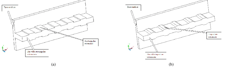
A fin is a surface that extends from an object to increase the rate of heat transfer to or from the environment by increasing convection. Extensions on the finned surfaces is used to increases the surface area of the fin in contact with the fluid flowing around it. So, as the surface area increase the more fluid contact to increase the rate of heat transfers from the base surface as compare to fin without the extensions provided to it. Types of extension provided on fin such as (a) Rectangular extensions, (b) Trapezium extensions, (c) Triangular extension, and (d) Circular Segmental extension.
(a) (b)
ISSN: 2319-8753
International Journal of Innovative Research in Science,
Engineering and Technology
(An ISO 3297: 2007 Certified Organization)
Vol. 3, Issue 5, May 2014
Copyright to IJIRSET www.ijirset.com 12055
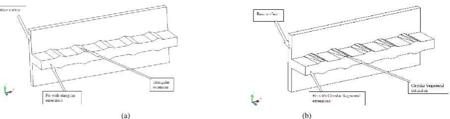
(a) (b)
Fig. 2: Fin with (a) Triangular extensions,(b) Circular segmental extensions.
II. LITERATURE REVIEW
Abdullah, H. Alessa et. al. [1] had studied the natural convection heat transfer enhancement from a horizontal rectangular fin embedded with equilateral triangular perforations. The heat dissipation rate from the perforated fin is compared to that of the equivalent solid one. The effect of geometrical dimensions of the perforated fin and thermal properties of the fin was studied in detail. They concluded that, For certain values of triangular dimensions, the perforated fin can result in heat transfer enhancement. The magnitude of enhancement is proportional to the fin thickness and its thermal conductivity. The perforation of fins enhances heat dissipation rates and at the same time decreases the expenditure of the fin material.
B. Ramdas Pradip et. al. [2] had studied the many industries are utilizing thermal systems wherein overheating can damage the system components and lead to failure of the system. In order to overcome this problem, thermal systems with effective emitters such as ribs, fins, baffles etc. are desirable. The need to increase the thermal performance of the systems, thereby affecting energy, material and cost savings has led to development and use of many techniques termed as “Heat transfer Augmentation”. This technique is also termed as “Heat transfer Enhancement” or “Intensification”. Augmentation techniques increase convective heat transfer by reducing the thermal resistance in a heat exchanger. Many heat augmentation techniques has been reviewed, these are (a) surface roughness, (b) plate baffle and wave baffle, (c) perforated baffle, (d) inclined baffle, (e) porous baffle, (f) corrugated channel, (g) twisted tape inserts, (h) discontinuous Crossed Ribs and Grooves. Most of these enhancement techniques are based on the baffle arrangement. Use of Heat transfer enhancement techniques lead to increase in heat transfer coefficient but at the cost of increase in pressure drop.
Golnoosh Mostafavi [3] had investigated the steady-state external natural convection heat transfer from vertically-mounted rectangular interrupted finned heatsinks. After regenerating and validating the existing analytical results for continuous fins, a systematic numerical, experimental, and analytical study is conducted on the effect of the fin array and single wall interruption. FLUENT and COMSOL Multiphysics software are used in order to develop a two-dimensional numerical model for investigation of fin interruption effects. Results show that adding interruptions to vertical rectangular fins enhances the thermal performance of fins and reduces the weight of the fin arrays, which in turn, can lead to lower manufacturing costs.
ISSN: 2319-8753
International Journal of Innovative Research in Science,
Engineering and Technology
(An ISO 3297: 2007 Certified Organization)
Vol. 3, Issue 5, May 2014
Copyright to IJIRSET www.ijirset.com 12056 III. DESIGN AND ANALYSIS OF FIN WITH EXTENSIONS
A. Designing of Fin with AutoCAD
The fin with various extensions are design with the help of design software AutoCAD by using the AutoCAD 2D and 3D commands like as 2D commands polyline, arc, mirror , pedit ,& 3D commands extrude. The line draws with the Polar mode. In this mode length of the line and angle of the line is defined to draw the design. [5] The angle is measured in anti-clock direction starting from the first quadrant.
Main Fin specifications:
Length, l = 40mm = 0.04 m, width, b = 240 mm = 0.24 m and thickness, y = 15mm = 0.015 m.
Specifications of various extensions shown in the Fig. 3 and number of extensions used on main fin is 10 nos.
(a) (b)
(c) (d)
Fig. 3: (a)Rectangular extension,(b) Trapezium extension, (c) Triangular extension, (d) Circular segmental extension.
B. Analysis of Fin for Heat Transfer with Simulation Software
After the creation of design the next process is to analysis the fin for heat transfer by using software Autodesk® Simulation Multiphysics. Firstly import the design model AutoCAD DWG file (*.dwg) in the Autodesk® Simulation Multiphysics software this will make the result as AutodeskSimulation FEA model (*.fem) file format. Now, select the type of analysis as thermal analysis for steady-state heat transfer process. Assign unit system as customization length in mm, temperature in °C and thermal energy in J. Now from the 3D mesh setting set 60% mesh size towards fine. Generate the mesh of design.
ISSN: 2319-8753
International Journal of Innovative Research in Science,
Engineering and Technology
(An ISO 3297: 2007 Certified Organization)
Vol. 3, Issue 5, May 2014
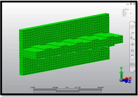
Copyright to IJIRSET www.ijirset.com 12057 Fig. 4 shows that meshing of the model. The meshing result shows that the solid mesh surface part having 3310 elements created, final mesh size is 4.75669 mm and surface mesh contain 3305 nodes, 9909 lines. The mesh type is mix of brick, wedges, pyramids and tetrahedra.
C. Assigning Load and Constraints to the Meshed Model
In this assign the material having thermal conductivity, convection coefficient of heat transfer for fluid, temperature of surface and ambient temperature as:
Thermal conductivity, k = 40 W/m°C = 0.04 J/(s mm °C)
Convection coefficient of heat transfer, h = 40 W/m2 °C = 0.00004 J/(s mm2 °C) Temperature of wall surface at which fin attached, to = 55 °C
Ambient temperature, ta = 30 °C
D. Results from the Analysis
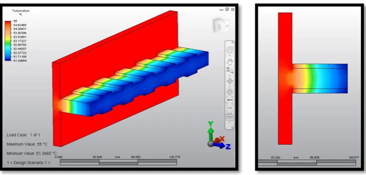
After the generation of mesh and assigning of load and constraints next step is to run the simulation for the model. This proceeds for the analyzing the steady-state heat transfer process and finally obtain the required result contour of temperature.
Fig. 5: Temperature contour for fin with rectangular extensions.
ISSN: 2319-8753
International Journal of Innovative Research in Science,
Engineering and Technology
(An ISO 3297: 2007 Certified Organization)
Vol. 3, Issue 5, May 2014
Copyright to IJIRSET www.ijirset.com 12058
(a) (b)
Fig. 6: Temperature contour for fin with(a)Trapezium extensions, (b) Triangular extensions.
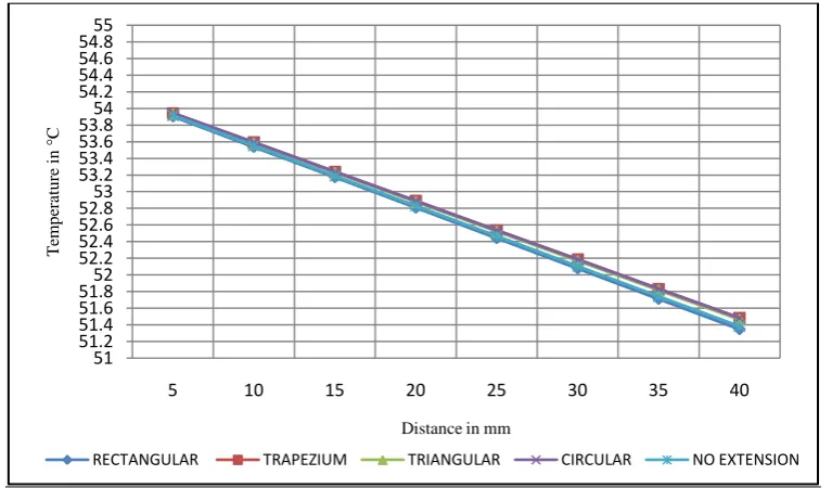
Similarly the resultant Fig. 6 & Fig. 7 shows that variations of temperature along length of fin with trapezium extensions, triangular extensions and fin with circular segmental extensions, fin without extensions that the temperature reduces from fin base to the tip end of the fin.
(a) (b)
Fig. 7: Temperature contour for fin (a)Circular segmental extensions, (b) Without extensions.
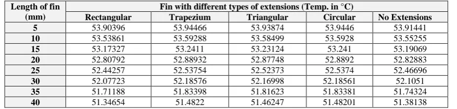
TABLE-1
COMPARISON OF TEMPERATURE VARIATIONS ALONG WITH LENGTH OF FINS
Length of fin (mm)
Fin with different types of extensions (Temp. in °C)
Rectangular Trapezium Triangular Circular No Extensions
5 53.90396 53.94466 53.93874 53.9446 53.91441
10 53.53861 53.59288 53.58499 53.5928 53.55255
15 53.17327 53.2411 53.23124 53.241 53.19069
20 52.80792 52.88932 52.87748 52.8892 52.82883
25 52.44257 52.53754 52.52373 52.5374 52.46696
30 52.07723 52.18576 52.16998 52.18561 52.1051
35 51.71188 51.83398 51.81623 51.83381 51.74324
40 51.34654 51.4822 51.46247 51.48201 51.38138
ISSN: 2319-8753
International Journal of Innovative Research in Science,
Engineering and Technology
(An ISO 3297: 2007 Certified Organization)
Vol. 3, Issue 5, May 2014
Copyright to IJIRSET www.ijirset.com 12059
Fig. 8: Plot showing the temperature variations along with length of fin with rectangular extensions, trapezium extensions, triangular extensions,
circular segmental extensions and fin without extensions.
IV. RESULTS ANDDISCUSSIONS
Heat transfer calculated by using the heat transfer governing differential equation for the fin of finite length and loses heat by convection [6],
Q
fin=
ℎ𝑃𝑘𝐴
𝑐𝑠(t
o– t
a)
tanh ml + 𝑘𝑚ℎ
1+ 𝑘𝑚ℎ tanh (ml )
for which the given length of fin (l in m), thickness of fin (y in m), width of fin (b in m),thermal conductivity of fin (k in W/m°C ), coefficient of convective heat transfer (h in W/m2 °C ) , temperature at base of fin (to in °C),temperature of
the ambient fluid (ta in °C). After the calculations of heat transfer rate of various fin geometry now it is the time to
compare the increase in heat transfer rate for the given geometry of fin which is shown in Table-2. The fin without extensions having 21.7665 W heat transfer value.
TABLE-2
COMPARISON OF HEAT TRANSFER FOR VARIOUS EXTENSIONS ON FIN.
Types of extensions Heat transfer
(in W)
Increase in heat transfer (in W)
Percentage increase in heat transfer (in %age)
Fin with rectangular extensions 24.5557 2.7892 12.93
Fin with trapezium extensions 22.9052 1.1387 5.23
Fin with triangular extensions 22.4495 0.683 3.14
Fin with circular segmental extensions 22.7155 0.949 4.36
51 51.2 51.4 51.6 51.852 52.2 52.4 52.6 52.853 53.2 53.4 53.6 53.854 54.2 54.4 54.6 54.855
5 10 15 20 25 30 35 40
T em p er at u re i n ° C
Distance in mm
ISSN: 2319-8753
International Journal of Innovative Research in Science,
Engineering and Technology
(An ISO 3297: 2007 Certified Organization)
Vol. 3, Issue 5, May 2014
Copyright to IJIRSET www.ijirset.com 12060 Now, for the discussions the heat transfer through fin with different extensions calculated by considering the changes in ambient fluid temperature from 28 °C to 18 °C as shown in the Table-3.
TABLE-3
HEAT TRANSFER THROUGH FIN AT AMBIENT TEMPERATURE 28°C TO 18°C
Type of extensions Qfin in W at ambient temperature
28 °C 26 °C 24 °C 22 °C 20 °C 18 °C
Rectangular 26.516 28.480 30.444 32.408 34.373 36.337 Trapezium 24.738 26.570 28.403 30.235 32.067 33.899 Triangular 24.246 26.041 27.837 29.634 31.429 33.225 Circular segmental 24.536 26.355 28.171 29.988 31.806 33.623 Without extensions 23.508 25.249 26.991 28.732 30.473 32.215
The use of fin with different extensions provides the increase in the heat transfer rate as compare to fin without extensions shown in the Table-4.
TABLE-4
PERCENTAGE INCREASE IN HEAT TRANSFER FIN WITH EXTENSIONS
Type of extensions Percentage increase in heat transfer fin with extensions
28 °C 26 °C 24 °C 22 °C 20 °C 18 °C
Rectangular 12.796 12.797 12.793 12.794 12.798 12.795 Trapezium 5.232 5.232 5.232 5.231 5.231 5.227 Triangular 3.139 3.137 3.134 3.139 3.137 3.135 Circular segmental 4.373 4.380 4.372 4.371 4.374 4.371
Table-5 shows that the effectiveness of fin with rectangular extensions, trapezium extensions, triangular extensions and circular segmental extensions.
TABLE-5
EFFECTIVENESS OF FIN WITH EXTENSIONS
Type of extensions Effectiveness
28 °C 26 °C 24 °C 22 °C 20 °C 18 °C
Rectangular 5.846 5.846 5.846 5.846 5.846 5.846 Trapezium 5.656 5.656 5.656 5.656 5.656 5.655 Triangular 5.756 5.756 5.756 5.756 5.756 5.756 Circular segmental 5.408 5.408 5.408 5.408 5.408 5.408
V.CONCLUSIONS
The use of fin (extended surface) with extensions, provide efficient heat transfer:
Fin with extensions provide near about 5 % to 13% more enhancement of heat transfer as compare to fin without extensions.
Heat transfer through fin with rectangular extensions higher than that of fin with other types of extensions.
Temperature at the end of fin with rectangular extensions is minimum as compare to fin with other types of extensions.
The effectiveness of fin with rectangular extensions is greater than other extensions.
ISSN: 2319-8753
International Journal of Innovative Research in Science,
Engineering and Technology
(An ISO 3297: 2007 Certified Organization)
Vol. 3, Issue 5, May 2014
Copyright to IJIRSET www.ijirset.com 12061 REFERENCES
[1]. Abdullah, H. Alessa and Mohammed, Q. Al-Odat, “Enhancement of Natural Convection Heat Transfer from a Fin by Triangular Perforations of Bases Parallel and Toward its Base”,The Arabian Journal for Science and Engineering, vol. 34, pp. 531-544, 2009. [2]. B. Ramdas, Pradip and K. Kumar, Dinesh, “A Study on the Heat Transfer Enhancement for Air Flow through a Duct with Various
Rib Inserts”,International Journal of Latest Trends in Engineering and Technology, vol. 2, issue 4, pp. 479-485, 2013.
[3]. Golnoosh Mostafavi, “Natural Convective Heat Transfer from Interrupted Rectangular Fins”,MASc, Simon Fraser University, Canada, 2012.
[4]. Sable M.J., Jagtap S.J., Patil P.S., Baviskar P.R. and Barve S.B., “Enhancement of Natural Convection Heat Transfer on Vertical Heated Plate by Multiple V-fin array”, IJRRAS, vol. 5, issue 2, pp. 123-128, 2010.