Effect of Changing the Substrate in Multilayer
Micro Strip Antenna
Nivedita S.Mahadik
1, Prof.Sheetal Bhujade
2P.G. Student, Department of ExTC, Saraswati College of Engineering, Kharghar, Maharashtra, India1
Assistant Professor, Department of ExTC, Saraswati College of Engineering, Kharghar, Maharashtra, India2
ABSTRACT: This paper presents the effect of changing the substrate in Multi layer parasitic Micro strip Antenna at 5.8GHz . This antenna is designed by using different substrates for different layers. First layer element is made of FR4 substrate while other layers are of different substrates. Fractals are added on the top layer of antenna & it's effects are observed.
KEYWORDS: Micro strip Antenna, Rectangular Patch, Fractals, Co-axial feeding, Return Loss , Gain, Smith Chart, VSWR.
I. INTRODUCTION
Today's wireless systems requires the antennas of higher performance with small dimensions. To fulfil these requirements researchers are looking for more advanced antenna designs. Antennas which are used for these applications should be of low profile, light weight, low volume. All these requirements are overcome by using Micro strip antennas. Fractal is new class of geometry. The concept of fractal antenna came from fractals existing in nature. Antennas can be simulated by using different software's like IE3D, CST, HFSS. Antennas can be designed at different frequencies for different applications.
Generally, the structure of patch antenna consists of dielectric substrate which is on planar ground plane with radiating
element on other side of substrate which is prepared with conducting materials [1]. Micro strip Antennas have several
advantages & several disadvantages. These can be overcome by using different structures. Here, multilayer antenna is having three layers out of that first layer is of FR-4 substrate & top layer is of Rogers 5880. Second layer is change to examine the variations in results. For variations the materials which are used FR-4 of 1.6mm thickness & Rogers 5880 of 0.508mm thickness. These materials have been selected according to the availability in the market.
II. FRACTAL
The term Fractal means broken or irregular fragments. Each fractal is composed of multiple iterations of single geometry. It describes a complex set of geometries ranging from self similar to other irregular structure. The unique feature of fractals such as self- similarity and space filling. Here, the Sierpinski's carpet fractal geometry for rectangular shape is used. Here, the first iteration of fractal is used and its effects are studied.
Fig 1 shows geometry Sierpinski's carpet and there is another type of geometry in fractal is Sierpinski's gasket. That is used for triangular shapes.
III. DESIGN OF RECTANGULAR PATCH ANTENNA
The Rectangular patch Micro strip antenna can be designed at frequency of 5.8 GHz. The materials which are used for this multi layer antenna are FR-4 & Rogers RT 5880.
A. Design steps at 5.8 GHz frequency: 1.Calculation of the Width (W)
𝑊 = 𝑐
2𝑓 2
ɛ𝑟+1 (1)
2. Calculation of Effective Dielectric constant (ɛ𝑒𝑓𝑓) :
ɛ𝑒𝑓𝑓 = ɛ𝑟+1
2 +
ɛ𝑟−1
2 1 + 12 ℎ
𝑊 ^(− 1
2 ) (2)
3. Calculation of Effective length (𝐿𝑒𝑓𝑓):
𝐿𝑒𝑓𝑓 = 𝑐
2𝑓√ɛ𝑒𝑓𝑓 (3)
4.Calculation of Length Extension (ΔL) :
𝛥𝐿 = 0.412ℎ(ɛ𝑟𝑒𝑓𝑓+0.3) (
𝑊 ℎ+0.264 )
(ɛ𝑟𝑒𝑓𝑓−0.258 ) (𝑊ℎ+0.8)
(4)
5.Calculation of the resonant length of patch ( L):
𝐿 = 𝐿𝑒𝑓𝑓 − 2𝛥𝐿 (5)
IV. FEEDING TECHNIQUE & SIMULATION SETUP
Feeding techniques are also important for designing the antenna. There are different types of feeding techniques for Micro strip antenna out of that co- axial feed method is adopted for this paper. The outer conductor of co-axial probe is connected to ground plane. The outer conductor is of copper while inner conductor is of Teflon. By the availability of latest simulation software, it has become very easy to implement our ideas. Here, the total size of antenna is 60mmx60mm. Total height of antenna is 8.225mm.
V. FABRICATION & TESTING
This antenna is fabricated and then tested by using VNA in laboratory. It consists of ground plane, first layer of FR-4 substrate, second and third layer are of RT- Duroid . Here, the middle layer substrate is changed & its results are observed during testing.
The antenna is proposed at 5.8 GHz frequency Fig.2 shows the top view of antenna after fabrication Tested and simulated results are discussed below. The size for first layer patch is 11.5mmx11.5mm.
VI. SIMULATION RESULTS
A. RETURN LOSS
Here, multilayer antenna is fabricated and simulated by using different materials. First and second layer both are of FR-4 material which is having thickness 1.6mm. While, upper layer is of RT 5880 of 0.508mm thickness. It is the parameter which indicates the amount of power that is "lost" to the load and doesn't return as a reflection. It is usually expressed as the ratio in dB relative to the transmitted signal power. Return loss is caused by impedance mismatch between two or more circuits.
Fig.3 Return loss for Rogers 5880 in second layer
Plot of return loss is shown in Fig.3. Here, return loss is -46.75dB which is shown in Fig 3 & in FR-4 it is -36dB. The band for both is narrow band.
B. VSWR
It is the ratio between maximum voltage and minimum voltage along transmission line. Fig.4 shows VSWR value. 1.02:1 which denotes a maximum standing wave amplitude that is 1.02 times greater than the minimum standing wave value.
Fig 4.VSWR for Rogers 5880 substrate in second layer
By using FR-4 substrate in second layer of multilayer antenna it is 1.02 & for Rogers 5880 it is 1.11.
C. GAIN
Gain of antenna is actual realized quantity which is less than directivity due to Ohmic losses in antenna. It can also be defined as the ratio of maximum radiation intensity in given direction to the maximum radiation intensity from a reference antenna produced in the same direction with same power input.
Fig 5.Gain for Rogers 5880 substrate in second layer
D. SMITH CHART
It is the tool of visualizing impedance of transmission line and antenna system as function of frequency. Smith chart is used to display an actual antennas impedance measured on Virtual network analyser (VNA).
Fig 6.Smith Chart for Rogers 5880 substrate in second layer
Fig 6 shows the smith chart when Rogers 5880 substrate is used in middle layer. Fig shows 48Ω impedance during simulation which is close to 50Ω which is required.
VII. EXPERIMENTAL RESULTS
Both multilayer antennas are tested by using Virtual network analyser for 5.8GHz frequency. Here, the measured results are discussed. The antenna parameters like return loss, VSWR and smith chart are measured under free space condition.
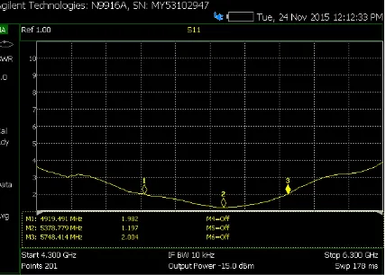
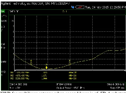
Fig 7.Return loss for multilayer antenna when second layer is of FR--4 substrate
Fig 8.Return loss for multilayer antenna when second layer is of
of Rogers RT5880 substrate
Fig 8 shows the return loss for Rogers 5880 substrate used for second layer here it is -22.04dB. Graph shows the centre frequency is shifted which is 4.8GHz.
Fig 9.Smith Chart for multilayer antenna when second layer is
FR-4 substrate
.
Fig 9 shows the smith chart when for second layer FR-4 substrate is used. 50.06Ω-j8.69Ω shows that there is perfect
impedance matching. From this it is conclude that antenna is capacitive.
Fig.10 shows VSWR which is 1.19 which is sufficient for any antenna. Practically, for any antenna it should be between 1-2.
Fig 11.VSWR for multilayer antenna when second layer is of FR-4 substrate
Fig.11 shows VSWR which is 1.17 when FR-4 substrate is used in second layer of antenna at 4.8GHz frequency.
Fig 12.Smith Chart for multilayer antenna when second layer is of Rogers 5880 substrate
Fig 12 shows the smith chart from that one can conclude whether the antenna is capacitive or inductive. Equation 44.50Ω+ j 4.87Ω shows the antenna is inductive.
VIII. CONCLUSION
REFERENCES
[1] Girish Kumar and K.P.Ray , Broadband Microstrip Antenna, Boston : Artech House , 2003. [2] C.A.Balanis, Antenna Theory, 2nd ed. New York : John Wiley & Sons, Inc, 1997.
[3] R.Jothi Chitra, A Sulganya And V. Nagaranjan " Enhanced Gain of Double U-Slot Micro Strip Patch Antenna Array For Wi Max Application" IEEE 2012.
[4] Dipika S. Sagne, Prasanna L.Zade, Rahul Batra " Design & Implementation Of Boadband Traingular Micro strip Planar Array for Wireless Communication" IEEE International Conference On Advanced Communication Control And Computing Technologies ( ICACCT), 2012. [5] Mohamed Ehetnaway And Widad Ismail " A Micro strip Antenna Array for Indoor Wireless Dynamic Environments" IEEE TRANSACTIONS On
Antennas And Propagation, Vol.57, No.12, December 2009.