Analysis of Advanced Controllers for
Temperature Control in a Heat Exchanger
Saranya.SN1, Dr.Prabhakaran.D2, Dr.Thirumarimurugan.M3
P.G. Student, Department of Chemical Engineering, Coimbatore Institute of Technology, Coimbatore,
Tamil Nadu, India1
Associate Professor, Department of Chemical Engineering, Coimbatore Institute of Technology, Coimbatore,
Tamil Nadu, India2
Associate Professor, Department of Chemical Engineering, Coimbatore Institute of Technology, Coimbatore,
Tamil Nadu, India3
ABSTRACT: The main goal of the experimental shell and tube heat exchanger presented in this paper is to control the temperature of the outgoing fluid to a desired set point in spite of different disturbances. The entire heat exchanger system is modelled using the experimental data, and the output transfer function is developed for the system. A proportional-integral-derivative (PID) controller using Ziegler-Nichols method, and internal model controller are tuned, this paper investigates the fuzzy logic control system design method for a heat exchanger. To verify the effectiveness simulations are done using Matlab-Simulink.
KEYWORDS:Heat Exchanger, Transfer function, Fuzzy, Internal model Controller
I. INTRODUCTION
The shell and tube of heat exchanger is where heat transfer process occurred. The performance of heat exchanger depends on the accuracy of both elements. Therefore, both components have to be controlled in order to get a considerable result in process. For this purpose, the actual dynamics of both shell and tube of the heat exchanger is crucial. It is the most general type of heat exchanger in oil refineries and other huge chemical processes, and is suitable for higher-pressure applications
Fig.1: Shell and tube heat exchanger
Fig.2: General block diagram of the process
VALVE HEAT
EXCHANGER
II. MATHEMATICALMODELING
In the heat exchanger system, actuator, valve, sensor are mathematically modeled using the Available experimental data. The data are summarized below. [13]
Time constant = 30 sec
Heat Exchanger response to variation of process fluid flow gain=1oC/ (kg/sec) Heat Exchanger response to variation of process fluid temperature gain=1oC/oC Steam Control valve capacity = 1.6 kg/sec
Control valve Time constant = 3 sec
The range of temperature sensor = 50oC to 150oC Temperature sensor Time constant = 10 sec
From the data, transfer function and the gain are obtained as below. Transfer function of process =
Transfer function of valve = . Gain of the Valve = 0.75 Transfer function of sensor = .
Transfer function of temp disturbance =
Transfer function of flow disturbance =
III. PIDCONTROLOFHEATEXCHANGER
PID controller is the most used controller because it is simple to operate and very robust. The latest implemented PID controller is based on a direct digital design. These digital PID has many algorithms to develop their performance, for example anti wind-up, auto-tuning, adaptive, fuzzy fine-tuning and Neural Networks with the necessary operations remaining the same. Here Zeigler-Nicholas tuning rule is used for the PID tuning since it provide easy tuning formulae to find out the P, PI, PID control parameters[14] For the PID Controller in the heat exchanger, the tuned parameters obtained are Kp =8.533, Ti =0.3006, Td =32.495. Usually, initial design values of PI controller obtained by all means to be adjusted repeatedly through computer simulation until the closed loop system performs effectively until the desired the result is obtained. The performance terms such as Rise time Overshoot, Settling time and error; By tuning value of parameters Kp, Ki and Kd of the PID controller the steady state can be improved. The output of this is shown in the below graph at the end of the paper.
IV. FUZZY
Fig.3:Fuzzy Rule Base
The model of simple fuzzy controller control signal depends on the measured inputs error and the change in error. The inputs are most usually tough or crisp measurements from equipment. A dynamic controller would have supplementary inputs, for example derivatives, integrals, or preceding values of measurements backwards in time. The block fuzzifications convert each input data to degrees of membership by a hunt for in one or numerous membership functions. The rules may use some variables, both in the condition and the termination of the rules. Basically, a linguistic controller has rules in the if-then format, but they can be available in different formats. The final result of fuzzy set must be converted to a number that can be sent to the process as a control signal. This operation is called defuzzification. Output scaling is also relevant. In this case the output is defined on a customary universe it must be scaled to engineering units.
The table that stated below are the fuzzy rules that have been used for tuning the process under control these rules have been framed in order to get a better control performance than other controllers which are under study.
Table1: Rules for fuzzy
The figure that are represented below are the represented as the specification of the rules that are used for framing the fuzzy logic.
(b)
(c)
Fig4: (a), (b), (c) Representation of fuzzy in Max-Min
V. INTERNAL MODEL CONTROL
The IMC principle states that the accurate control can be achieved only if the control system has either implicitly or explicitly some representation of the process to be controlled.
Fig5: General Block Diagram of Internal Model Controller
By using the following rules and considering the input one can design a IMC Controller:
Initially the process model is separated into two terms we determine a transfer function that has minimum phase characteristics .A system has non-minimum phase uniqueness if its transfer function contain zeros in the right half plane or transport lags, or both. Or a system has minimum phase uniqueness. For step change in disturbance is determined by
= (1)
The IMC controller is obtained by multiplying it with the transfer function of the filter f(s) that can be represented as
f(s) =
( ) (2)
Where is the filter parameter and n is an integer finally the equation of IMC can be obtained as
(3)
The conventional transfer function Gc, use is formed with GI and above equation is obtained and thereby process model, Gc turns out to be equal to a PID controller multiplied by a first-order transfer function thus
= 1 + + ( ) (4)
Where, , , , are the function of the process in the GI and G
The experimental data are taken and are modeled accordingly as stated above and the following results have been obtained
= (5)
= 4.9875
(3 + 1)(30 + 1)(90 + 33 + 1)(−90 −33 + 1)
=(3 + 1)(30 + 1)(90 + 33 + 1)
4.9875
1
( + 1)
In Practice λ is taken more than the time constant value, Here, the value of λ is taken as 1. Substituting the value to the
above equation we get a transfer function of Internal Model Controller denoted as Gc Gc= ( . . ) (6)
VI. SIMULATION AND RESULTS
The following represents the Simulation Of P, PI, PD, PID Controllers they are done the find out the best control response from the conventional controllers
(b)
Fig6: (a) Block diagram representation of P, PI, PD, PID Controllers, (b) Simulation Graph of P, PI, PD, PID Controllers
From the above comparison it is seen that the PID has a good response when comparing with the controllers such as P, PI, PD the evaluation the above results are given below. These state that the PID has a better response than the other controller like P, PI and PD.
Table2: Comparison for the Above Result
S.No Controller Rise Time (sec)
Overs hoot (%)
Settling Time (sec)
1 P 13.346 1.131 Error-0.22 2 PI 2.354 1.893 Error-0.09 3 PD 20.72 1.132 235 4 PID 18.94 1.129 196
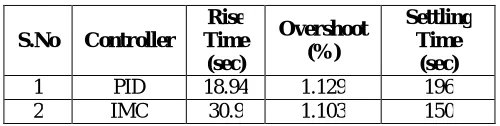
The following are the representation of the Simulation of PID and IMC Controllers to are done in order to compare the performance of the both the controller to find the best one
(a)
(b)
The above figure represents the performance analysis of both the IMC and PID controller form which it is inferred that the overshoot and setting time is less when compared with that of the conventional PID controller.
The table below gives the overall idea of the controller response that are made in the above diagram.
Table3: Comparison for the Above Result
S.No Controller
Rise Time
(sec)
Overshoot (%)
Settling Time
(sec)
1 PID 18.94 1.129 196 2 IMC 30.9 1.103 150
The following are the representation of the Simulation Of PID, IMC And Fuzzy Controllers which are done to compare the Fuzzy with the Both of Convectional PID and Advanced IMC controller.
(a)
(b)
Fig8: (a) Block diagram of IMC, PID and Fuzzy Controllers, (b) Simulation graph of PID, IMC and Fuzzy
The above figures are the representation of advanced controllers such as IMC, Fuzzy and the conventional controller PID and their response to the process implemented.
The table represents the response of the system that are tuned which clearly indicates that the fuzzy has more advantage than the other controllers that are under study
Table 4: Comparison for the Above Result
S.No Controller
Rise Time
(sec)
Overshoot (%)
Settling Time
(sec)
VII. RESULTS AND DISCUSSION
From the above discussions that were made it is concluded that the both the fuzzy and the IMC has good control in the heat exchanger temperature control. In fuzzy it is seen that there is no overshoot when that compared either that of IMC and PID controllers while the IMC has a fast settling time when compared to PID and Fuzzy controller.
VIII. FUTURE SCOPE
The future work can be done by implementing more intelligent controllers such as combing fuzzy and neural network (i.e) Neuro-Fuzzy, or by combing internal model control and Fuzzy (i.e)Fuzzy Internal Model Control.
REFERENCES
[1]. M. V. Despande, “Process control system”, pp19-25, pp 135-140
[2]. Chemical Process Control by George Stephanopoulas, 2003, Prentice-Hall of India Pvt. Ltd., pp 209-211.
[3]. Nagrath, I. J. and Gopal M. “Control System Engineering: third Edition, New Delhi 1999.
[4]. Coughanowr D R, “Process systems analysis and control”, McGraw-hill international edition, 1991, pp 339-344
[5]. Ian G Hom et.al, "Improved Filter Design in Internal Model Control," Ind. Eng. Chem. Res., vol. 35, no.10, pp. 3437-3441, Oct 1996.
[6]. Krishna Kant “Computer Based Industrial Controller, PHI.
[7]. Naim A. Kheir “System Modeling and Computer Simulation, pp. 4-9.
[8]. SubhransuPadhee, YuvrajBhushanKhare, Yaduvir Singh “Internal Model Based PID Control of Shell and Tube Heat Exchanger
System,”IEEE, JAN 2011.
[9]. Ahmad Ali and SomnathMajhi, "PI / PID Controller Design based on IMC and Percentage Overshoot Specification to Controller design Set
point Change," ISA Trans, 48, pp. 10-15, Jan 2009.
[10]. Gang Fu et.al, "An IMC-PID Controller Tuning Strategy Based on the DE and NLJ Hybrid Algorithm," in Proc. Int. Colloq Com put,Commun,
Control, Manage., pp. 307-310, Aug 2009.
[11]. T. Liu and F. GAO, "New Insight in to Internal Model Control Filter Design for Load Disturbance Rejection,” lET Control the. Appl., vol. 4,
issue 3, pp. 448-460, Mar 2010.
[12]. Mohammad Reza Faieghi and Abbas Nemati “On Fractional-Order PID Design”, Applications of MATLAB in Science and Engineering.
[13]. Subhransu Padhee, YuvrajBhushanKhare, Yaduvir Singh Internal Model Controller Based PID Controller of Shell and Tube Heat Exchanger ,
“IEEE, JAN 2011
[14]. KiamHeongAng, Gregory Chong and Yun Li, “PID Control System Analysis Design, and Technology,” IEEE Trans, Control
Syst.Technol.,vol 13, 4,pp.559-576, JAN2009.
[15]. Chhaya Sharma, Sanjeev Gupta, Vipin Kumar“Modeling and Simulation of Heat Exchanger using Soda Recovery” Proceedings of the World
Congress on Engineering 2011 Vol II WCE 2011, July 6 - 8, 2011, London, U.K
[16]. Nianben Zheng, Wei Liu*, Zhichun Liu, Peng Liu, Feng Shan.”A numerical study on heat transfer enhancement and the flow structure in a
heat exchanger tube with discrete double inclined ribs”,School of Energy and Power Engineering, Huazhong University of Science and Technology, Wuhan 430074, China
[17]. Arny Leroy*, Michel Bernier.”Development of a novel spiral coil ground heat exchanger model considering axial effects”Ecole Polytechnique
de Montreal, Departement de Genie Mecanique, Case Postale 6079, Succursale “Centre-Ville”, Montreal, Quebec H3C 3A7, Canada
[18]. Feng Wang, Caihua Liang*, Mingtao Yang, Chen Fan, Xiaosong Zhang.”Effects of surface characteristic on frosting and defrosting behaviors
of fin-tube heat exchangers”School of Energy and Environment, Southeast University, 2 Sipailou Road, Nanjing 210096, PR China.
[19]. Benamar Bouhacina a, Rachid Saim a, Hakan F. Oztop b, *a“Numerical investigation of a novel tube design for the geothermal borehole heat
exchanger”a) Energetic and Applied Thermal Laboratory(ETAP) Faculty of Technology, Abou Bakr Belkaid University, BP 230, 13000 Tlemcen, Algeria.b) Department of Mechanical Engineering, Technology Faculty, Firat University, 23119 Elazig, Turke.y
[20]. Zadeh, L. A., Fuzzy Sets, Information & Control, vol. 8, no. 3, pp. 338–353, 1965.
[21]. Zadeh, L. A., Fuzzy Algorithms, Information & Control, vol. 12, no. 2, pp. 94–102, 1968.
[22]. Isermann, R., On Fuzzy Logic Applications for Automatic Control, Supervision, and Fault Diagnosis, IEEE Transactions on Systems, Man
and Cybernetics: Part A-Systems and Humans, vol. 28, no. 2, pp. 221–235, 1998
[23]. Dote, Y., and Ovaska, S. J., Industrial Applications of Soft Computing: A Review, Proceedings of the IEEE, vol. 89, no. 9, pp. 1243–1265,
2001.
[24]. Sen, M., and Goodwine, B., Soft Computing in Control, in The MEMS Handbook, ed. M. Gad-el-Hak, 2nd ed., pp. 16.1–16.35, CRC Press,