ABSTRACT
YANG, LI. Structural Design, Optimization and Application of 3D Re-entrant Auxetic Structures. (Under the direction of Ola Harrysson, and Denis Cormier.)
In this work, a 2D re-entrant honeycomb structure was adapted into a 3D auxetic structure,
and modeled via both the Timoshenko beam theory and the Euler-Bernoulli beam theory. Design parameter driven models were derived that could predict various mechanical properties
of this auxetic structure such as strength, elastic modulus and Poisson’s ratio.
The models were verified with a combined approach of finite element analysis (FEA) and physical experiments, taking advantage of additive manufacturing processes such as electron
beam melting (EBM), Objet 3D-printing, and selective laser sintering (SLS). Results showed
general agreement between the theoretical models and the experiments. The errors introduced in the modeling as well as the manufacturing processes are discussed and taken into
considera-tion in the design theories.
This work provides a guideline for future applications of 3D re-entrant auxetic structures such as sandwich panel applications. It provides a methodology for future designs of other
c
Copyright 2011 by Li Yang
Structural Design, Optimization and Application of 3D Re-entrant Auxetic Structures
by Li Yang
A dissertation submitted to the Graduate Faculty of North Carolina State University
in partial fulfillment of the requirements for the Degree of
Doctor of Philosophy
Industrial Engineering
Raleigh, North Carolina
2011
APPROVED BY:
Denis Cormier
Co-chair of Advisory Committee
Mike Rigsbee
Harvey West Ola Harrysson
DEDICATION
BIOGRAPHY
The author was born in Kunming, a beautiful and lively city full of cultural atmosphere in
Yunnan Province of China. He was the only child of a family with mixed background of mechanical engineering, Chinese literature and history, and his childhood was greatly benefited
from the instruction and influence of his parents.
After the author received his Bachelor’s degree of mechanical engineering from Tsinghua University (Beijing, China) in 2004, he started to feel deeply interested in the metal additive
manufacturing areas. He applied to the Rapid Prototyping and Bio-manufacturing Lab in
Ts-inghua University, and studied under the instruct of Dr. Feng Lin and Dr. Yongnian Yan, whom were the pioneer researchers in the additive manufacturing field in China. Under their
supervi-sion, the author become familiarized with various research topics in the additive manufacturing
areas. In his thesis work, the author focused on the heat transfer analysis and temperature field control of the electron beam selective melting (EBSM) process, and implemented the preheating
devices for the EBSM system.
After graduated from Tsinghua University with Master’s degree in 2007, the author went to the Department of Industrial & System Engineering at North Carolina State University
(Raleigh, NC, USA), and continued the research on additive manufacturing under the
super-vision of Dr. Denis Cormier and Dr. Ola Harrysson, with the focus on design and analysis of cellular structures, the fabrication and the experimental evaluation of these structures using
additive manufacturing processes such as electron beam melting (EBM), Objet and selective laser sintering (SLS).
The author has published five journal papers, two conference papers, with seven manuscripts
ACKNOWLEDGEMENTS
I feel great fortunate to work with Dr. Denis Cormier and Dr. Ola Harrysson, who were among
the first to be dedicated to the research of metal additive manufacturing in the world. They are not only advisors, but also friends, whom influenced me with their deep understanding in
engineering and additive manufacturing. The modeling and design of the auxetic structure
is an open topic with many challenging and interesting problems, and they have been most supportive to all my research attempts, realistic or unrealistic, successful or unsuccessful.
All these highly theoretical and calculation intensive work could not have been done without
the help of Dr. Harvey West, who is an expert in mechanical engineering and material science. Whenever I needed help, I would walk down to the first floor of Daniels Hall, and he was always
there. He is also the most strict reviewer, who always catches my slightest miscalculations.
I want to thank Dr. Mike Rigsbee for his help and supportive advises on the microstructure and fractographic analysis of the samples made by the EBM process. Although a majority of
my research is focused on the mechanical modeling, when it came to the material properties
and microstructural analysis, he was always there to help.
I would also like to take this opportunity to thank all my colleagues and friends, Guha
Prasaana, Tushar Mahale, Omer Cansizoglu, Chun Park, and especially Kyle Knowlson, Tim
Horn, and Hazman Bin Hasib. It is my great pleasure to have them around, discuss the issues with me, help me with various equipment and systems, perform experiments for me, and support
me all the time. I also want to thank our lab supervisor Dan Leonard for his help whenever I needed to deal with any machining operations.
Special thanks to Jason Low, who does not only helped me with equipments and processes,
but also encouraged me and supported me like a family senior. Beside research, I also learned a lot about teaching from him.
Last but not least, I want to thank Dr. Russel King for the financial support throughout the
TABLE OF CONTENTS
List of Tables . . . vii
List of Figures . . . .viii
Chapter 1 Introduction . . . 1
1.1 Mesh structures . . . 1
1.1.1 Introduction . . . 1
1.1.2 Applications of mesh structures . . . 1
1.1.3 Manufacturing of mesh structures . . . 3
1.1.4 Current limitations . . . 11
1.2 Auxetic structures . . . 12
1.2.1 Background introduction . . . 12
1.2.2 Potential applications . . . 13
1.3 Rapid Manufacturing . . . 13
1.3.1 Background . . . 13
1.3.2 Electron Beam Melting (EBM) . . . 16
1.3.3 Capabilities and limitations . . . 18
1.4 Current study . . . 19
Chapter 2 Modeling and characterization of mesh structures . . . 21
2.1 Introduction . . . 21
2.2 Mechanical characteristics of mesh structures . . . 23
2.3 Design consideration of regular mesh structures . . . 26
2.3.1 Design for strength . . . 26
2.3.2 Design for energy absorption . . . 30
2.4 Conclusions . . . 32
Chapter 3 Modeling of auxetic structures . . . 33
3.1 Introduction . . . 33
3.1.1 Auxetic structures . . . 33
3.1.2 Structural characteristics of auxetic structures . . . 39
3.1.3 Properties of auxetic structures . . . 44
3.2 Design of 3D re-entrant auxetic structure . . . 46
3.2.1 Structural design . . . 46
3.2.2 Large deflection modeling . . . 48
3.2.3 Small deflection model . . . 52
3.2.4 Compressive properties . . . 54
3.2.4.1 Compressive properties in they direction . . . 54
3.2.4.1.1 Poisson’s ratio νxy . . . 57
3.2.4.1.2 Effective modulus Ey . . . 62
3.2.4.1.3 Failure strength σF−Y . . . 68
3.2.4.2.1 Poisson’s ratio νxy . . . 78
3.2.4.2.2 Effective modulus Ex . . . 84
3.2.4.2.3 Failure strength σF−X . . . 87
3.2.5 Tensile properties . . . 93
3.2.5.1 Tensile properties in they direction . . . 93
3.2.5.1.1 Poisson’s ratio νyx . . . 96
3.2.5.1.2 Effective modulus Ey . . . 96
3.2.5.1.3 Failure strength σF−Y . . . 97
3.2.5.2 Tensile properties in thex direction . . . 99
3.3 Conclusions . . . 102
Chapter 4 Experiments and numerical simulations of auxetic designs . . . .103
4.1 Model design . . . 103
4.2 Experimental procedures . . . 108
4.3 Results and discussion . . . 112
4.3.1 Poisson’s ratio . . . 119
4.3.2 Effective modulus . . . 121
4.3.3 Failure strength . . . 125
4.3.4 Other errors introduced by EBM process . . . 129
4.3.5 Size effect . . . 134
4.4 Conclusions . . . 136
Chapter 5 Design for sandwich structures with auxetic cores . . . .138
5.1 Sandwich structures for impact energy absorption . . . 139
5.1.1 Structural design . . . 139
5.1.2 Experimental procedures . . . 142
5.1.3 Results and discussion . . . 143
5.2 Sandwich structures for bending . . . 152
5.2.1 Structural design . . . 152
5.2.2 Experimental procedures . . . 154
5.2.3 Results and discussion . . . 156
5.3 Conclusions . . . 165
Chapter 6 Conclusions. . . .166
LIST OF TABLES
Table 1.1 Comparison of metal AM technologies . . . 16
Table 2.1 In-plane mechanical properties of several 2D periodic mesh structures [1] . 27 Table 3.1 Specification of Ti6Al4V . . . 57
Table 4.1 Design parameters for compression in y . . . 105
Table 4.2 Design parameters for compression in x . . . 105
Table 4.3 Design parameters for Poisson’s ratio measurement . . . 107
Table 4.4 Design parameters for size effect simulation . . . 108
Table 4.5 Parameters of the samples . . . 113
Table 4.6 Strut sizes of the samples . . . 114
Table 4.7 Poisson’s ratio values from various methods . . . 121
Table 4.8 Comparison of values for effective modulusEy . . . 122
Table 4.9 Comparison of values for effective modulusEx . . . 123
Table 4.10 Comparison of values of compressive strength in y . . . 126
Table 4.11 Comparison of compressive strength values in x . . . 127
Table 5.1 Design parameters for the re-entrant auxetic structure for impact . . . 139
Table 5.2 Designs of various cellular structures for impact . . . 141
Table 5.3 Dimensions and relative densities of the SLS samples . . . 145
Table 5.4 Strut sizes and face dimensions of the samples . . . 145
Table 5.5 Build orientation of various structures . . . 147
Table 5.6 Estimation of loss of energy absorption abilities for various structures . . 147
Table 5.7 Comparison of different structures made with Ti6Al4V by EBM . . . 148
Table 5.8 Design parameters for the re-entrant auxetic structure for bending . . . . 152
Table 5.9 Designs of various cellular structures for bending . . . 154
Table 5.10 Actual parameters of the samples made by EBM for bending . . . 157
Table 5.11 Bending properties of various structures . . . 160
Table 5.12 Comparison of FEA and experiments . . . 162
LIST OF FIGURES
Figure 1.1 Relative density of a mesh structure . . . 2
Figure 1.2 Pratt truss in truss bridge design [2] . . . 3
Figure 1.3 Different types of mesh manufacturing processes . . . 4
Figure 1.4 Melt gas injection casting to manufacture Al foam [3] . . . 5
Figure 1.5 Gas releasing agent casting to manufacture Al foam [4] . . . 6
Figure 1.6 Sintering-dissolution method to manufacture Al foams [5] . . . 8
Figure 1.7 Extruded maraging steel square honeycomb part [1] . . . 9
Figure 1.8 Sheet metal working method to produce pyramidal truss cores [6] . . . . 10
Figure 1.9 3D Kagome structure made by wire-weaving method [7] . . . 11
Figure 1.10 Layout of EBM system . . . 17
Figure 1.11 Some parts made by EBM . . . 19
Figure 2.1 Some designs of 2D mesh structures [1] . . . 22
Figure 2.2 Polyhedral unit cells [8] . . . 23
Figure 2.3 A Kagome unit cell . . . 24
Figure 2.4 Compressive strain-stress curve of regular foam structures [3] . . . 25
Figure 2.5 Tensile strain-stress curve of regular foam structures [9] . . . 26
Figure 2.6 Design of the hexagonal honeycomb structure . . . 28
Figure 2.7 Difference between the ideal model and the finite model for . . . 30
Figure 3.1 Auxetic frame structure with hinges and springs [10] . . . 34
Figure 3.2 Isotropic auxetic structure by Lakes [11] . . . 34
Figure 3.3 Bending plane of regular structure and auxetic structure [12] . . . 37
Figure 3.4 Examples of rigid-hinges type of model . . . 39
Figure 3.5 Examples of rigid-fibrils type of model . . . 40
Figure 3.6 High magnification SEM photograph of PTFE auxetic structures [13] . . 41
Figure 3.7 Several auxetic re-entrant models . . . 41
Figure 3.8 Schematic of the compression of re-entrant honeycomb . . . 43
Figure 3.9 Re-entrant auxetic structure . . . 46
Figure 3.10 Design parameters for re-entrant auxetic structure . . . 47
Figure 3.11 Loading and deflection of the re-entrant struts . . . 49
Figure 3.12 Deflection angles of the re-entrant strut, small deflection model . . . 53
Figure 3.13 Deflection in x and y directions, small deflection model . . . 53
Figure 3.14 Simplification of the structure compressed in y . . . 54
Figure 3.15 Relationship between coordinate systems of re-entrant struts under com-pressive stress in y direction, large deflection model . . . 56
Figure 3.16 Poisson’s ratios in y direction under compression with different designs: . 58 Figure 3.17 Poisson’s ratio in y direction under different stress levels: large deflection model . . . 59
Figure 3.20 Comparison of Poisson’s ratios in y between two models . . . 61
Figure 3.21 Comparison of Poisson’s ratios in y between two models: no shear effect 62 Figure 3.22 Effective modulusEy/Es under compression in y with different designs: . 63 Figure 3.23 Effect of stress level on the effective modulus under compression in y: . . 64
Figure 3.24 Effect of solid modulus on the effective modulus under compression in y: 64 Figure 3.25 Correlation between effective modulus and Poisson’s ratio in y . . . 65
Figure 3.26 Normalized effective modulusEy/Es with different designs: . . . 65
Figure 3.27 Comparison of effective modulus between two models . . . 66
Figure 3.28 C1 values with different designs for compression in y . . . 67
Figure 3.29 C1 values with different designs for compression in y . . . 68
Figure 3.30 Distribution of normal stress on the cross section . . . 70
Figure 3.31 Progression of yielding across the re-entrant strut’s cross section . . . 70
Figure 3.32 Normalized failure strength in y with different designs . . . 72
Figure 3.33 Failure surface of 3D re-entrant auxetic structures in y . . . 73
Figure 3.34 Correlation between plastic failure strength and Poisson’s ratio in y . . . 74
Figure 3.35 Values of constantn2 with different design parameters, y direction . . . . 75
Figure 3.36 Values of constantC2 with different design parameters, y direction . . . 75
Figure 3.37 Compressive loading of re-entrant honeycomb structure in x direction . . 76
Figure 3.38 Decomposition and analysis of the strut components compressed in the x direction . . . 77
Figure 3.39 Deflection of the re-entrant half strut under compressive stress in the x direction: . . . 79
Figure 3.40 Poisson’s ratios of re-entrant auxetic structure compressed in x direction 80 Figure 3.41 Effect of stress level on the Poisson’s ratio in x under compression: . . . . 81
Figure 3.42 Effect of solid modulus on the Poisson’s ratio in x under compression: . . 81
Figure 3.43 Deflection angle of re-entrant struts under compression in x: . . . 82
Figure 3.44 Deflection of the re-entrant strut under compression in x: . . . 82
Figure 3.45 Poisson’s ratio in x with different designs: small deflection model . . . . 83
Figure 3.46 Comparison of Poisson’s ratio in x with different designs between two models . . . 84
Figure 3.47 Effective modulusEx/ES under compression in x with different designs: 85 Figure 3.48 Correlation between effective modulus and Poisson’s ratio in x: . . . 86
Figure 3.49 Effect of stress level on the effective modulus in x under compression: . . 86
Figure 3.50 Effect of solid modulus on the effective modulus in x under compression . 87 Figure 3.51 Effective modulus in x with different designs, small deflection model . . . 88
Figure 3.52 Comparison of effective modulus in x between two models . . . 88
Figure 3.53 C1 values with different designs for compression in x . . . 89
Figure 3.54 Force components for type 1 re-entrant honeycomb for compressive strength 89 Figure 3.55 Normalized failure strength in x with different designs . . . 90
Figure 3.56 Correlation between the compressive strength and the Poisson’s ratio in x direction compression . . . 91
Figure 3.57 n2 with different designs for compression in x . . . 92
Figure 3.58 C2 with different designs for compression in x . . . 92
Figure 3.59 The loading analysis of the unit cell under tensile stress in y direction . . 93
Figure 3.61 The dimension change for different coordinate systems under tension in y 95
Figure 3.62 Deflection of the re-entrant strut under tension in y direction: . . . 95
Figure 3.63 Poisson’s ratio values for re-entrant auxetic structure under tension in y . 96 Figure 3.64 The percentage difference of Poisson’s ratio values between tension and . 97 Figure 3.65 Normalized effective modulus of re-entrant auxetic structure under ten-sion in y: . . . 98
Figure 3.66 The difference of effective modulus values in y direction under tension and 98 Figure 3.67 The loading of the re-entrant auxetic structure under tension in x direction 99 Figure 3.68 The analysis of the re-entrant struts under tension in x direction . . . 100
Figure 3.69 Dimension change of the re-entrant half strut under tension in x direction 100 Figure 3.70 Deflection of the re-entrant strut under tension in x: . . . 101
Figure 4.1 Design scheme for the re-entrant lattice structure . . . 104
Figure 4.2 Design parameters for the re-entrant honeycomb structure . . . 105
Figure 4.3 Sample models for compressive testing using Ti6Al4V in EBM . . . 106
Figure 4.4 Design of the samples for Poisson’s ratio measurements . . . 107
Figure 4.5 Modeling for size effect . . . 109
Figure 4.6 Experimental setup for compressive testing of Ti6Al4V samples . . . 110
Figure 4.7 The setup for simulation of structures . . . 111
Figure 4.8 Iso-Clipping function for failure strength in SolidWorks Simulation . . . . 112
Figure 4.9 Re-entrant auxetic samples . . . 112
Figure 4.10 Effective dimensions of a strut made by EBM . . . 114
Figure 4.11 Reduction of effective length of the re-entrant strut . . . 114
Figure 4.12 Typical strains-tress curve for auxetic samples compressed in y direction 116 Figure 4.13 Boundary effect of cellular structure . . . 116
Figure 4.14 The deflection and failure of vertical struts under compressive stress . . . 117
Figure 4.15 The crushing of the single layer under compressive stress for A3 sample . 117 Figure 4.16 Loading of the vertical struts at edges . . . 118
Figure 4.17 Typical strains-tress curve for auxetic samples compressed in x direction 119 Figure 4.18 SEM of the fracture surface of Ti6Al4V struts made by EBM . . . 120
Figure 4.19 Comparison of effective modulusEy . . . 121
Figure 4.20 Comparison of effective modulusEx . . . 123
Figure 4.21 Comparison between the modulus in x direction between FEA and theory124 Figure 4.22 Comparison of modulus between auxetic structures and regular foam structures . . . 125
Figure 4.23 Comparison of modulus between auxetic structures and regular foam structures . . . 126
Figure 4.24 Comparison of failure strength in y . . . 126
Figure 4.25 Comparison of failure strength in x . . . 127
Figure 4.26 Internal stress from the locking of torsion warping of a rectangular beam 128 Figure 4.27 Comparison of compressive strength in x between FEA and theory . . . . 129
Figure 4.28 Comparison of strength between auxetic structures and regular foam structures . . . 130
Figure 4.30 Sensitivity of modulus with parameter variations . . . 131
Figure 4.31 Sensitivity of strength with parameter variations . . . 133
Figure 4.32 Cross sections of struts made by EBM . . . 134
Figure 4.33 Cross section shape design for evaluation . . . 134
Figure 4.34 Effect of cross section shape to the mechanical properties . . . 135
Figure 4.35 Size effect for Poisson’s ratio values . . . 136
Figure 4.36 Size effect for effective modulus . . . 137
Figure 5.1 The sandwich plate with auxetic core . . . 140
Figure 5.2 Design of the unit cells of various cellular structure . . . 141
Figure 5.3 Build Orientation of samples in EBM . . . 142
Figure 5.4 Impact testing setup . . . 144
Figure 5.5 Design of the unit cells of various cellular structure . . . 146
Figure 5.6 Compressive strength of various sandwiches . . . 148
Figure 5.7 Modulus of various sandwiches . . . 149
Figure 5.8 Total energy absorption for various structures . . . 150
Figure 5.9 Average peak force of various structures . . . 151
Figure 5.10 Energy absorption of various structures during top perforation . . . 151
Figure 5.11 Peak force of various structures during top perforation . . . 152
Figure 5.12 The sandwich panel with auxetic core . . . 153
Figure 5.13 Experimental setup for the three point bending test . . . 154
Figure 5.14 Actual setup for the bending test . . . 155
Figure 5.15 FEA of the bending of the sandwich panel . . . 156
Figure 5.16 The shape of the auxetic sandwich under bending . . . 158
Figure 5.17 FEA of the bending of various sandwich structures . . . 159
Figure 5.18 Sandwich panel dimensions . . . 162
Figure 5.19 Comparison of bending modulus for various sandwich structures . . . 164
Chapter 1
Introduction
1.1
Mesh structures
1.1.1 Introduction
Mesh structures, also referred to as lattice structures or foam structures, are constructed of ligaments and nodes that connect the ligaments. Mesh structures exist widely in nature, include
the honeycomb and the lotus root. Mesh structures are also manufactured and used in various
applications, with the honeycomb filler structure and truss bridge being good examples. Mesh structures could be treated as special types of open cell foam structures with a large
fraction of air contained within the structures. There has been plenty of work related to the
modeling, analysis and manufacturing of open cell foam structures, which has been mainly focused on stochastic foams. These works established theoretical basis for general mesh
struc-tures, and provided references for this current work. In this section, the general properties, process methods and applications of mesh structures and open cell foam structures in general
will be discussed.
1.1.2 Applications of mesh structures
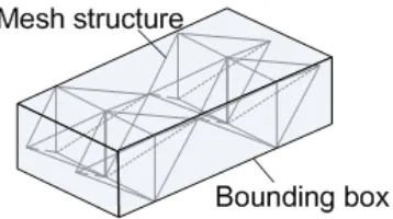
One significant characteristic of mesh structures is their low relative density (i.e. the density of the actual structure bounding geometry divided by the density of the solid material, as
shown in Fig. 1.1), which brings about various advantages. Compared to solid structures, mesh
structures usually possess much higher specific strength. Also, due to their complex porous internal features, mesh structures also exhibit unique flux characteristics and therefore could
be used as flow pressure modulators, thermal insulators, fire retardants, electromagnetic field
barriers or acoustic dampers. Some applications of mesh structures include:
Figure 1.1: Relative density of a mesh structure
• Thermal insulator layers
• Shock absorption devices
• Bio-active interface for implants
• Catalytic media
• Structural frames
• Sound absorption layers
• Electromagnetic modulator for electronic devices
Sandwich structures are widely used in automobile, aerospace, sports, electronics and archi-tecture industries. Sandwich structures consist of a thick core and two stiff face skins attached
to the core. The core structures are often porous foam/cellular structures, which provide shear
strength at low density. Sandwich structures with cellular cores are of specific interest to the automobile and aerospace applications where light weight is a critical criteria. The large surface
area to volume ratio of the mesh structures makes them ideal candidates for use as catalytic
media and bio-interfaces in various applications. In addition, the large volumetric ratio of air and the small solid cross sectional area significantly limits the coefficient of heat transfer of the
mesh structures, making them effective for use as thermal insulation.
Open cell foam structures are widely used in the aerospace industry as thermal insulator and impact absorbers. In the design of external tanks for the space shuttles, NASA had been
using a multi-player insulating (MLI) system which contains multiple layers of mesh structures
and a sprayed-on foam insulation [14]. Recently, a more integrated foam core shield (FCS) has been approved and put into design to supplant the MLI systems [15]. The FCS system is a
sandwich panel structures with the polymer foam core acting as the energy absorber as well
bodies to reduce engine noise transmission into the cabin and to improve the comfort of flight.
Metallic foam wrapping installed around the airplane engine could help reducing noise emissions by 4-5dB [16].
In the design of permanent prostheses using metal as materials, mesh structures are
imple-mented into the surface design of the implants in order to increase the bio-activity of the tissue in-growth region. The mesh structures act as the scaffold for cell attachment and migration,
and facilitates the formation of the tissue structure. The porosity facilitates the tissue cell
seeding and diffusion of both cells and nutrients, and therefore improves the bonding between the implant and the tissue. In addition, the mesh structure design of the implants could also
modify the modulus of the implants in order to match the modulus of bone and therefore avoid
the stress shielding effect.
The design of mesh structures is also employed in large frame structures such as truss
bridges, building frames, and construction load-bearing frames. In these applications, the
mesh structures are usually constructed by hinge jointed or fixed jointed individual trusses with specific patterns. For example, in the design of a truss bridge, one of the common truss
structures is the Pratt truss, which includes vertical truss members and diagonal truss members
that slope down towards the center, as is shown in Fig. 1.2.
Figure 1.2: Pratt truss in truss bridge design [2] Reprinted with permission of Wikipedia
In the design of a radome, the sandwich configuration is often used, which consists of a low dielectric foam or honeycomb core in order to reduce the thermal conductivity and
at the same time tailor the electromagnetic reflectivity over a given frequency range. For a
completely different purpose, some foam structures are used to absorb electromagnetic signals to create a stealth effect, which is termed ”radar-absorbent material” or RAM [17]. Through
the modification of characteristics such as material, pore size, pore distribution, relative density, etc., the properties of the mesh structures could be tailored in a wide scale.
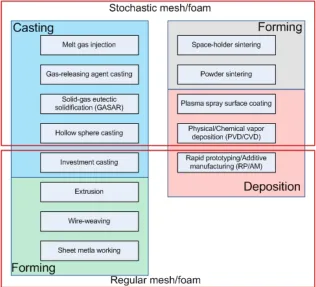
1.1.3 Manufacturing of mesh structures
Over hundreds of years, various methods have been developed to manufacture mesh and foam
1.3, these processes could be categorized as casting, powder metallurgy, deposition and forming,
and the resulting structures could be categorized as stochastic or regular, depending on whether the geometry of the structure is predetermined or random.
Figure 1.3: Different types of mesh manufacturing processes
In the study by Hahn et al., titanium hydride porous mesh layers were coated on a smooth Ti6Al4V surface using plasma spray. The resulting porous structures had relative densities of
about 0.4-0.5 and a good bonding with the substrate [18]. Due to the nature of the process,
plasma spray is capable of producing porous near net shape features and porous surface features with macroporosity as well as microporosity [19, 20]. However there is no control over the
characteristics of the porosity such as distribution and size of the pores. In addition, the
coating is also limited within the line-of-sight of the source, which might result in non-uniform coating films. A wide range of materials could be used for plasma spray, because the high
temperature during the ionization is sufficient for melting virtually any material. Therefore,
Melt gas injection is a conventional method to produce foam structures. Some variations
of the process exist, however the basic procedures are demonstrated in Fig. 1.4. During this process, the premixed materials are heated up to the liquidus temperature and melted. Gas
is injected into the melt to form pores directly [3]. The temperature of the liquid is carefully
controlled to be close to the melting point so the viscosity is adequate. In order to further increase the viscosity, stabilizer particles such as aluminum oxide or silicon carbide are added
into the melts [3, 21]. Increased viscosity helps to impede drainage in the bubble membrane
and therefore to stabilize the foam. The melt is continuously pulled out from the crucible by the conveyor belt and solidifies during the process, and the air bubbles are trapped in the metal
matrix and form pores. This process could produce continuous long foam sheets with the width
and thickness restricted by the size of the crucibles.
Figure 1.4: Melt gas injection casting to manufacture Al foam [3] Reprinted with the permission of Elsevier
The melt gas injection method is suitable for aluminum and its alloys because they have
relatively low density and do not oxidize much during the process. The porosity and the size of the pores are controlled primarily through the gas flow rate and the temperature of the
each pore. During the pulling of the conveyor belt, the foam structures are extended in the
pullout direction which result in anisotropic structures. Moreover, the foams produced by this method could only be closed cell foams. Some commercial foams such as CYMAT are produced
via this method.
Another alternative method is to add gas-releasing agents into the melt instead of air bub-bles. This method is schematically demonstrated in Fig. 1.5. Calcium is added into the melt to
increase the viscosity. After the viscosity reaches the desired level, the foaming agent is added
into the stirring melts. A widely used foaming agent is titanium hydride (TiH2), which
decom-poses into titanium and gaseous H2 when it is heated above 465◦C [3]. After the foaming agent
is added, the melt gradually expands due to the generation of H2 bubbles, and forms foam
structures when eventually solidified. By controlling the parameters such as foaming agent content, viscosity, temperature and cooling rate, very homogenous foams could be produced
via this method [4, 21]. This method could produce closed cell foams with large porosity and
relatively uniform structures, however it still does not have control over the characteristics of individual pores and therefore the precise predictions of properties. Another restriction is that
since H2has significant embrittlement effect on many metal alloys, and the decomposition speed
is too high for high melting point alloys, aluminum alloys are the primary type of metal used by this method. Some alternative foaming agents have been investigated such as carbonates
and nitrates, and iron, steels and nickel alloys could be foamed using these agents. However they haven’t been widely used for commercial applications.
Figure 1.5: Gas releasing agent casting to manufacture Al foam [4] Reprinted with the permission of TMS
Solid-gas eutectic solidification (GASAR) takes advantage of the fact that many metal-hydrogen binary phase diagrams exhibit a eutectic point. When the metal saturated with H2
gas eutectic reaction, thus generating porous structures. The morphology of the pores is highly
sensitive to the process parameters such as pressure, melt superheat, cooling rate and container geometry [3, 4, 22]. Therefore, it is difficult to achieve full control of the pore characteristics.
The pore size and pore distribution is non-uniform because of the concurrent growth of bubbles
of different sizes and their coalescence. Again due to the use of H2, the materials selection is
limited for practical purposes.
Some closed cell metal foams are made from a route similar to the powder metallurgy
technologies. The powders are premixed with foaming agents, and compacted into the base precursor. The precursors are then cut into pieces and put into a hollow mold. When the
powders are heated up to near the melting point of the matrix material, the foaming agents
decompose and release gas to form bubbles, and the precursor expands and fills up the mold to produce the foam structures. Because the blending of the foaming agents could be quite
homogeneous, the resulting distribution of pores is quite uniform, and some amount of control
of the pore size and shape could be achieved by controlling the parameters of the foaming particles. Although this method is mostly used to produce aluminum foams, other materials
such as tin, zinc, brass, and lead were tested with the selection of proper foaming agents [23].
Foams made by this method includes Alulight and Fraunhofer.
Another variation of the powder metallurgy sintering method is the space-holder method
[3, 24]. Two types of powders are premixed together, one is the metal matrix material, and the other is the space holder material that has a high melting point and is dissolvable in a
certain solvent. The precursor is then compacted under isostatic pressure. Two alternatives
could be adopted to generate the porosity. One is the sintering and leaching route, in which the precursor is sintered at the temperature near the melting point of the metal matrix, then
after it is cooled down the space holder material is dissolved by water, thus leaving the porous
metal matrix, as shown in Fig. 1.6 [5]. Another alternative is to leach the space holder first and then sinter the porous matrix to acquire the final strength. This method could produce
open cell foam structures with controlled pore size and morphology as well as the total porosity.
It could also have some amount of control of the distribution of the porosity given that the compacting process is efficient. One limitation of this method is that the characteristic of the
porosity is restricted by the morphology of the space holder materials. If the particle size of
the space holder material is dispersed, the resulting foam structure will have varied pore size. In the case such as demonstrated in Fig. 1.6, it is difficult to acquire spherical NaCl particles
due to its crystalline structures. Although spherical porosity is desired in many cases, it can
be very difficult to obtain such foam structures [24].
Investment casting is a conventional casting process that is capable of producing parts with
complex features, and it is also used to produce metal foams. The template (or pattern) foam
Figure 1.6: Sintering-dissolution method to manufacture Al foams [5] Reprinted with the permission of Elsevier
polymer foam was used for high melting point materials such as Ni alloys [25]. The template
is coated with mold casting slurry which is heat resistant, and is then dried and hardened
by the burnout process. The polymer template is also removed during the burnout process, leaving a negative pattern of the original foam structure. The desired material could then be
cast into the mold to produce the metal foam structure. After the metal solidified, the mold
shell is removed and the resulting foam is the exact replica of the original foam structure. One significant advantage of this method is that almost any material that could investment
cast could be used to produce the foam structure. However, the structure of the foam is not
controlled by the process itself, but rather the template that is produced by the preliminary foaming process. Periodic mesh structure templates could be produced via several techniques
such as polymer unit cell assembly and bent mesh assembly, and investment casting could then
be carried out to produce a metal mesh structure with precisely predetermined structure [26]. However the procedures become quite complicated.
Similar to the investment casting method, the metal deposition method uses polymer foams
as templates to produce metal foams. The metals are deposited directly on the templates via chemical vapor deposition (CVD), physical vapor deposition (PVD), electroplating or electron
beam directed vapor deposition (EB-DVD) [3, 27, 28]. After the deposition the template is
burned out and the resulting part is a foam structure with hollow struts. Post processing such as sintering is usually done to increase the mechanical properties of the foams. There exist some
limitations of this method. Electroplating requires conductive electrodes which necessitates a preliminary coating of metals on the template. The thickness of the coating is also limited.
CVD processing occurs at elevated temperatures at which the structural stability of polymer
controls. On the other hand, PVD processing is usually taken under vacuum environment in
which the effective coating could only occur within the line-of-sight of the vapor source, and will result in an uneven coating for complex foam structures. This method is mainly used for
research purpose due to its limited capability and high complexity.
In recent years, the hollow sphere method has emerged as a potential manufacturing method with a higher degree of control of the characteristics of the foams. The hollow particles are
pre-manufactured, and sometimes coated with binders. The particles could be sorted and sintered
or HIP-ed, and the resulting structure is a closed cell foam with porosity as high as 95% [3]. Alternatively, molten metal could be cast into the hollow sphere beds to produce a composite
structure with the casting material as the matrix and the hollow spheres as the reinforcement
[29]. Good bonding is ensured by metallurgical bonding between the two phases, and the resulting closed cell foams have pores with quite uniform characteristics. It is reported that
this metal foam composite exhibits superior properties compared with regular closed cell foams
due to the better control of the porosity characteristics.
An extrusion method has been used to produce 2D mesh structures with periodic cellular
features [1]. Ceramic paste consisting of metal oxides, water and a small amount of binder and
lubricant is prepared and extruded through a die into the desired shape. The dried precursor is then put into a hydrogen atmosphere to reduce metal from the oxides, it is then sintered to
acquire fully dense walls. Some amount of oxides and porosity remains in the final structures, impairing the strength and ductility of the parts. Fig. 1.7 shows one of the extrusions made by
this method using maraging steel. Some other structures extruded include hexagonal supercell,
regular hexagonal honeycomb, Kagome cell and diamond cell.
The sheet metal working method is commonly used to produce core structures for sandwich
panels. As shown in Fig. 1.8, a flat sheet metal piece is cut into corresponding mesh with a periodic array of holes (in the case of Fig. 1.8 it’s diamond-shaped), and bent along the
lines of the nodes to form the pyramidal truss cores. Multiple layers of bent sheet metal are
then brazed together using special binders [6]. This method is also used to produce the regular honeycomb cores that are now widely used in various applications [8]. The strength of the
structure produced by this method is largely affected by the strength of the brazing since the
general strength of the sheet metal is high. This method is well suited for mass production of relatively simple mesh structures, but becomes increasingly difficult or even infeasible when the
mesh geometries become complex.
Figure 1.8: Sheet metal working method to produce pyramidal truss cores [6] Reprinted with permission of Elsevier
Another method used by various researchers to produce the periodic mesh structures is
the wire-weaving method. Some structures that are difficult to produce with the sheet metal working process are made by this method such as Kagome structures [30–32]. The individual
wires of steel or other materials are twisted together until plastic deformation occurs and the
wires become helical, then the wires are fixed on the frame and woven together to produce the periodic mesh structures. An example of the final structure is shown in Fig. 1.9 [30].
The resulting structure possesses very high specific strength which is largely contributed by
the superior strength of the wire used [31]. The wire-weaving process is performed by manual operations, which make the fabrication of large scale 3D mesh structures extremely difficult.
Rapid prototyping (RP) technologies were first introduced around 1986, and after decades
of development, have developed into a large family of more than 20 different processes. RP processes have the capability to produce parts with almost any geometry directly from the
Figure 1.9: 3D Kagome structure made by wire-weaving method [7] Reprinted with permission of Elsevier
products. Originally, RP technologies were used almost exclusively for prototype
manufac-turing and evaluation. With recent development, the concept of RP has evolved into rapid
manufacturing (RM), which fabricates not only prototypes but also functional parts. There has been an increased interest in the manufacturing of mesh structures with RP/RM processes,
especially periodic mesh structures which have predetermined properties. Mesh structures
pro-duced via RP/RM processes could be used directly as final structures, or used as patterns for investment casting to produce metal foam structures [26, 33]. In combination with other
pro-cesses, RP/RM processes could make parts with a wide range of material selection, including
photo-curable resin, thermoplastics, rubber, ceramics, and some metal alloys, such as Ti6Al4V, tool steels, cobalt-chromium alloys, Al-alloys and coppers.
1.1.4 Current limitations
As discussed before, most processes for the production of mesh structures lack the ability of full control over the properties of the structures, which is caused by the inherit randomness in the
processes themselves or in the preforms, and sometimes by the large number of manufacturing
variables that are impractical to achieve full control. As a consequence, the properties of most mesh structures are determined empirically, which is not an effective way to optimize the design
and achieve specific properties according to application requirements.
low production rate. Although foaming process can produce foam structures, the quality of
the foams is largely stochastic. With increased requirements for the amount of control on the structure properties, the complexity of the process increases significantly. One extreme
example is the hand-made wire-woven structures, which requires high craft skills and labor
intensive works.
Rapid manufacturing technologies seem to provide a nice compromise between flexibility
and productivity. With the ability to produce metal mesh structures within several hours with
relatively high quality, they provide a suitable platform for the research and application of mesh structures for application purposes.
1.2
Auxetic structures
1.2.1 Background introduction
The word “auxetic” comes from the Greek word auxetikos which means “that which tends
to increase”. The first auxetic structure was reported in 1987 [11]. Auxetic structures exhibit
negative Poisson’s ratios in one or more directions. When stretched, they will become thicker in the direction normal to the applied loading direction. Some specially processed materials exhibit
auxetic behavior because of their unique microstructure, but auxetic behavior also readily exists
in regular materials with positive Poisson’s ratios. In most cases, it is the structural design that creates auxetic behavior. This seemingly odd behavior brought attention of many researchers,
and over the past two decades, there has been a large amount of work devoted to auxetic
structures. In most of the studies, the auxetic structures were modeled as various types of mesh or foam structures, with characteristically inverted struts that contribute to the auxetic
behavior. Similar to regular mesh structures, auxetic structures could be described by the
general foam structure model. However, auxetic structures have some appealing properties that make them different from the regular mesh structures. These properties include:
• Large shear modulus and shear strength;
• Good indentation resistance;
• Synclastic shape under bending moment;
• High fracture toughness;
• Unique acoustic and electromagnetic transmission.
the auxetic parts are still largely uncontrollable, and there has been few actual applications
reported so far.
1.2.2 Potential applications
Because of their unique properties, auxetic structures have potential in many different
applica-tions. Applications have been proposed from wine bottle corks [11] to radome sandwich panel
cores [34]. Auxetic structures could be used as robust shock absorbers, air seat cushions, fas-teners, air filters and mass filters. They could also be used in piezoelectric devices to maximize
the acoustic-to-electrical energy conversion [35].
Sandwich structures widely make use of various properties of mesh structures and foams.
In many applications, core shear is the leading cause of structural failure. On the other hand,
it is highly desired that the sandwich structures absorb more energy, and exhibit conforming bending when subjected to the bending moments. Auxetic structures could potentially provide
all the advantages, which makes them ideal candidates for the core structures.
Auxetic structures could also be potentially used in large scale structures. The superior stiffness of auxetic structure makes them desirable in the design of bridges and tall buildings.
Currently the predominant structural designs are based on the triangle because of its stiffness
and stability. However, triangle is not the most efficient mesh structure design in the perspective of overall performance. The properties of auxetic structures might lead to the solution of this
dilemma.
One greatest obstacle for auxetic structures is that there has not been a manufacturing method to date that could sufficiently control the properties of the auxetic structures. People
have only managed to produce structure that exhibit auxetic behavior in foam parts, and due
to the random nature of the foam structure, it is very difficult to control the dimensions and geometries of the unit cell within the structure. This makes it difficult to have any control over
the mechanical properties. Therefore, it is necessary to develop a method to manufacture
aux-etic structures with predetermined design parameters, and consequently enables the evaluation of the structures with comparison to the theoretical studies.
1.3
Rapid Manufacturing
1.3.1 Background
Since the first generation of the StereoLithography (SLA) system was introduced by 3D Systems
in 1986, rapid prototyping (RP) technologies have developed into a large family that includes
Electron Beam FreeForm Fabrication (EBF3), Laser Engineered Net Shaping (LENS), Direct Metal Deposition (DMD), and Ultrasonic Additive Manufacturing (UAM). The applications of RP technologies have also expanded to various areas such as biomedical implants,
archi-tectural design prototypes, mold making, custom made aerospace parts, replacement parts for
aerospace crafts and F1 racing cars, entertainment, art design, paleontology reconstruction, and many more. Sometimes referred to as “the next level” technology, RP realizes direct fabrication
of digital models by employing the layered manufacturing concept, which splits the 3D digital
model into layers, and fabricates the model layer by layer by adding material to generate a predetermined geometry for each layer. It is well known that RP technology provides various
advantages over the conventional manufacturing processes because of its unique conceptions,
which includes but not limited to:
• Capability to generate random complex geometries that are difficult or impossible for
other processes such as internal features, undercuts and pre-assembled parts;
• Decreased lead time from concept to product. No intermediate process is needed from
the model design to the prototype;
• Ease of design and process modification. The whole process is digitally driven, which can
easily be changed as needed;
• Low overall cost of products which benefit from the fact that this process is digitally
driven and can easily be changed;
• High accuracy fabrication. Feature resolution as fine as 25µm can be achieved for some
processes, which is suitable for analysis and design estimation.
The original applications of RP processes were focused on the rapid fabrication of prototypes.
Due to the limits on material selection and the relatively low part strength, parts produced by
RP processes were not used directly for functional purposes except in rapid tooling (RT), where the RP parts were used as the pattern for the manufacturing of tooling devices.
After two decades of development, most RP processes have the capability to produce
fully-dense functional parts, thanks to the development of new materials and processes. The concept of layer-by-layer deposition of materials has also led to the development of various micro/nano
fabrication technologies, such as Dip-Pen Nanolithography (DPN), Soft Lithography (SL) and
Atomic Layer Deposition (ALD). In order to better represent the ever developing industries, the term “rapid prototyping” was recently superseded by the now standard term as “additive
manufacturing” (AM) [36]. By definition, AM is the process of joining materials to make
SLS and 3DP, which are capable of using a variety of different types of plastic materials such
as polymers and elastomers.
Currently, many of the AM processes still lack the capability of producing functional metal
parts. For example, the SLS process utilizes a laser source to heat the powders selectively to
form “green parts”. This preform usually does not have the required strength and density, and post-sintering or infiltration needs to be performed in order to produce the final functional
part. On the other hand, with the rapid development of various industries such as orthopedics,
aerospace and high-performance automobiles, the demand for fully dense metal parts with com-plex shapes and excellent mechanical properties has increased significantly. Often the quantity
of the demand is small, for example, the replacement components for the old aircraft models
which are no longer produced by the original manufacturer, and the medical implants that have to be designed individually for each patients depending on the actual use. Conventional
man-ufacturing could not cope with the requirements because of both the limitation of capability
to produce complex features and the high cost of tools and molds associated that could not be justified.
In the past ten years or so, some AM processes specialized for metal materials have been
developed, such as SLM, LENS, EBF3, DMD, EBM and UAM. Most process utilizes high energy beams such as laser or electron beam to melt the metal, and therefore produce fully
dense metal parts that have mechanical strength that is often superior to cast parts. One exception is the UAM process, also referred to as ultrasonic consolidation (UC), which employs
micron-amplitude ultrasonic vibration, and creates a solid state metallurgical bond between the
surfaces of succeeding layers through the resulting micro-friction effect, and produces near-fully dense metal parts [37–41]. Because no phase change is involved in the process, UAM could
realize the manufacturing of structures with multiple materials with similar or dissimilar alloys.
The metallurgical reaction at the interfaces still requires further investigation [37, 38, 40]. As a result, the UAM process could theoretically be used on all weldable materials. For the other
processes, currently a limited selection of materials is available, including Ti6Al4V,
cobalt-chromium alloys, special types of Al-alloys, pure copper, several types of Ni-based superalloys, tool steels and stainless steels, and Ti-Ni intermetallic materials.
As the first energy sources used in the RP technologies, lasers possess various advantages
such as high stability, mature control technology, small beam diameter, and no vacuum re-quirement. However there also exist some drawbacks for lasers as the energy source for metal
processing. The energy absorption rate of metal is low for some lasers, such as the CO2 lasers.
In addition, the surface quality of the metal also affects the efficiency of the process. Laser absorption can be very low for highly reflective surfaces. Some AM technologies that use lasers
The electron beam requires a vacuum environment to operate. In addition, charge
dissipa-tion also becomes an issue because of the nature of the electron beam. However, electron beam energy is better absorbed by metals (theoretically 100%), and the electron beam does not have
optic reflection problem. Furthermore, the electromagnetic steering for electron beam is also
faster and more flexible. AM technologies that use electron beam energy includes EBF3 and EBM.
A brief comparison of the metal RM technologies is listed in Table 1.1. The Rapid
Pro-totyping Lab at North Carolina State University was the first US institute to have an EBM system. Currently the lab is equipped with two EBM systems, one S12 and one A2, along with
other additive manufacturing processes such as Objet, SLA and FDM. In the current study,
the EBM A2 system was employed to fabricate metal auxetic mesh structures for experimental purposes. In addition, an Objet Alaris 30 (Objet 30) was also employed in the studies where
relatively soft and ductile material was required.
Table 1.1: Comparison of metal AM technologies Process Power
(kW)
Layer thick-ness (mm)
Metal material Source
SLM 0.2-0.4 0.02-0.1 steel, Co-Cr, bronze-based al-loy, Inconel-718, stainless steel, Ti6Al4V, copper, Al-alloys
Laser
LENS 1.1 0.38 Ti6Al4V, Inconel-625 and 718,
316 stainless steel, H13 tool steel
Laser
DMD 1 0.1-1.6 H13 tool steel Laser
EBF3 42 2 Ti6Al4V, 2219 Al-alloy E-beam
EBM 4 0.05-0.1 Ti6Al4V, H13 tool steel, Co-Cr, Ti-Ni alloys, pure copper, 316 stainless steel
E-beam
UAM - 0.5-2 Various materials Ultrasonic
actuation
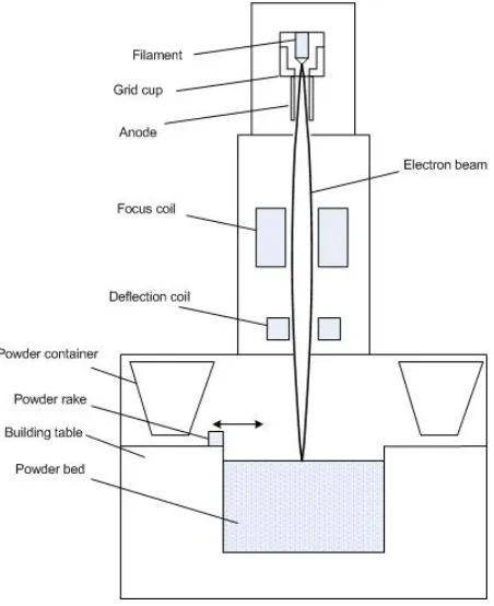
1.3.2 Electron Beam Melting (EBM)
The EBM process was developed by Arcam in 1999, and has become the most successful
com-mercial electron beam based AM system. As of this work, over 70 systems have been sold
worldwide, with predominant applications being aerospace and biomedical implants. The EBM system is illustrated in Fig. 1.10. The electron gun system is very similar to that used in
1000-1500V. Emitted electrons are focused by an electromagnetic coil to reach a minimum
beam size of about 0.5mm. The X and Y position control is realized through the magnetic field generated by two deflection coils with a maximum scan speed of over 1000mm/s. In the
building chamber, a powder spread system with double containers is used to deploy powders on
the powder bed. A rake moves between the two powder containers to spread the powder. After the rake has spread one layer of powder, the electron beam is selectively deflected according
to the shape of the current layer to melt the powder to form the desired geometry. After the
melting is finished, the building table lowers the powder bed by on layer thickness (as small as 0.05mm), and the rake spreads a new layer of powder. These procedures are repeated until the
whole build is finished.
Figure 1.10: Layout of EBM system
EBM typically uses Ti6Al4V, H13 tool steel and cobalt chromium. The powder bed is
preheated to form an initial sintered layer in order to reduce the thermal gradients and to improve interlayer bonding [42]. Another benefit of preheating is that the slightly sintered
powder could serve as complimentary support because of the improved strength of the sintered
larger energy input. There are several parameters that could be conveniently controlled in EBM,
including beam current, scan speed, beam diameter (degree of focus) and repetition number of melting. By adjusting these parameters, the optimal powder melting conditions are found.
In general, there must be sufficient energy input into each forming area in order to ensure
complete melting and void free microstructures. However, excessive heating results in large thermal gradients, which will cause residual thermal stresses that can warp the substrate or even
the part. Moreover, excessive heating introduces a high temperature environment, which will
lead to the formation of coarse microstructures that inevitably reduces the mechanical strength of the final parts. The EBM process could split the geometry of each layer into contour and
hatching sections that are scanned separately in order to ensure the geometry precision. Also,
the system could alter its hatching orientation, therefore enables various scanning strategies such as alternatively hatching in X or Y directions for consecutive layers in order to improve the
homogeneity of the temperature field. In short, the EBM process provides full flexibility from
manufacturing industrial standard parts to develop processes for new materials and structures.
1.3.3 Capabilities and limitations
EBM possesses the capability to produce fully dense metal parts with complex features. It could
fabricate parts with intricate internal features without using much support, such as the parts shown in Fig. 1.11. In recent years, the application of cementless implants has led to research
involving non-stochastic periodic mesh structures made by titanium alloys [43, 44]. Fig. 1.11(b)
and Fig. 1.11(c) demonstrates some of the examples. Adequate preheating helps to reduce the amount of energy needed in the melting step and therefore improves the distribution of heat,
resulting in uniformly high quality. The elimination of support for lightweight overhanging
features in these mesh parts avoids the problematic issue of post cleaning process. Process parameter themes for mesh structure have been developed for Ti6Al4V which can produce
parts with stable quality. They provide a reliable starting point for further improvement of the
process.
Some issues remain unsolved for EBM process in spite of its advantages. The first problem is
the surface quality. Due to the inevitable heat dissipation during the process, some loose powder
around the part geometry is heated and partially sintered during the melting process, therefore can stick to the outer surface of the part, generating somewhat “sandy” surface features. Most
of the powder could be removed by the succeeding powder blasting recovery process, however
some particles are more significantly sintered and will be partially melted together with the actual part. This reduces the aesthetics of the part and create surface defects. The heat
(a) Adaptor part [45] (b) Implant cup with mesh [45] (c) Al-alloy mesh cube
Figure 1.11: Some parts made by EBM Reprinted with permission of Arcam
Another issue is the microstructure. Although EBM can produce fully dense solid parts, mesh structures with small strut diameter have more serious heat dissipation issue due to the
large surface area. As a result, there is a much higher chance to form defects such as voids
or partial melting inclusions. Although not a serious problem for static mechanical properties, these micro-defects might serve as crack initiation sites that greatly deteriorate the fatigue
life of parts. Because the electron beam scanning occurs at the top layer of the part, strong
temperature gradients are formed in the direction normal to the layer. The grain growth will be favored in this direction, resulting in a very elongated grain morphology in the building
direction. As a result, it is expected that parts made by EBM will exhibit anisotropic properties,
and will have a generally lower strength compared with the wrought parts because of the relatively coarse grain size.
Initial experiments have shown that the minimum solid feature that the EBM can generate
without significantly losing strength is about 0.5-0.8mm. The smallest distance between two features is about 0.7mm.
1.4
Current study
In this work, the primary focus will be to establish a comprehensive model for two well-known
auxetic structures that are potentially suitable for various applications. Static properties such
as tensile strength, Poisson’s ratios, elastic modulus, as well as dynamic properties such as impact energy absorption will be discussed and modeled using analytical models. FEM analysis
and experiments with predetermined design configurations will be carried out to verify the
mechanical properties.
One particular focus of the application of sandwich structures with auxetic cores is the energy absorption ability. An experimental and theoretical hybrid approach will be carried out
to design and evaluate the various properties of the sandwich structure associated with energy
absorption performances.
To summarize, several objectives of this study include:
1. Modeling of relationships between design parameters and the mechanical properties such
as tensile and compressive modulus and strength, bending modulus and strength, Pois-son’s ratios and impact strength;
2. Validate the theoretical models of the re-entrant honeycomb auxetic structures;
3. Design and optimize the structure to meet the property requirements for energy absorbing
sandwich structures;
4. Evaluate the relationship between the process quality and the mechanical properties of
Chapter 2
Modeling and characterization of
mesh structures
2.1
Introduction
There exist two primary types of mesh structures, which are random meshes (foams) and
periodic meshes. Due to the development of mass production processes, foam structures have been widely used for various applications, such as heat insulation, shock absorption, space filler,
sound damping and catalyst media. On the other hand, relatively few periodic mesh structures,
such as hexagonal honeycomb structures, have been used for engineering purposes.
There are two types of foam structures, namely open cell foams and closed cell foams. Open
cell foams have pores that are interconnected with each other and usually also connected to
the surrounding environment. On the other hand, closed cell foams do not have interconnected pores, and these pores are usually enclosed in the cell walls. Because of the formation of
con-tinuous cell walls, closed cell foams exhibit stretch dominated failure mechanism, and therefore
are generally stronger than the open cell foams, which exhibit bending dominated failure mech-anism [8]. Some of the commercialized open cell foams and closed cell foams include Duocel
(open cell), Alulight (closed cell), Alcan (closed cell), and Alporas (closed cell).
Periodic mesh structures possess apparent advantages over the stochastic foam structures because of their controllable properties. The period of the structure occurs either in two or three
dimensions. Two-dimensional periodic mesh structures have 2D periodic features extruded in the third dimension, and therefore have anisotropic properties. These meshes are therefore
referred to as 2D mesh structures. The honeycomb structure is one example of a 2D mesh
structure. Fig. 2.1 shows some of the common 2D mesh structure designs. Theoretically any periodic unit cell that could fill up space by tiling (patterning) is a potential candidate for a 2D
of sandwich panels are usually highly anisotropic where high out-of-plane stiffness is usually
required.
(a) Square cell (b) Hexagonal honeycomb cell (c) Hexagonal supercell from equi-lateral triangles
(d) Kagome (e) Rectangular cell (f) Diamond cell
Figure 2.1: Some designs of 2D mesh structures [1] Reprinted with permission of Taylor & Francis
Three-dimensional periodic mesh structures have unit cells that are repeated in all three principal directions. They are usually more complicated in geometry and could possess isotropic
properties depending on the actual design. These types of mesh structures are therefore referred
to as 3D mesh structures. The design of 3D mesh unit cells are more difficult, and the restric-tions of seamless space filling determines that there could only be limited types of bounding
geometries that are available as design candidates. Fig. 2.2 listed several common polyhedral
unit cells. Among them only No. 2, 3, 4, 6 and 8 are space filling geometries. The unit cells could have more complicated internal features, however the bounding geometries are always
the Kagome structure. Despite its complex shape and non-orthogonal pattern, it could still be
contained into a cube which could in turn fill the space when the Kagome unit cell is patterned.
Figure 2.2: Polyhedral unit cells [8]
Reprinted with permission of Cambridge University Press
When in use, 2D mesh structures are usually loaded in the in-plane directions (the directions parallel to the 2D pattern direction), in order to take the advantage of the cell wall bending
during the deformation. In the third direction, the 2D meshes usually do not possess advantages
over simpler structures due to the increased propensity for elastic failure. By comparison, 3D mesh structures usually exhibit higher isotropy in all directions, therefore are potentially
more favorable for the design of multi-axial loading applications. Due to the limits of the
manufacturing feasibility, only a few 3D periodic mesh structures have been developed. Most of the periodic mesh structures currently used are 2D meshes.
2.2
Mechanical characteristics of mesh structures
There has been a large variety of research work dedicated to the characterization of mesh
structures and foams. The work done by Gibson and Ashby are considered to be the most
comprehensive [3, 8]. Because of the existence of a large portion of pore-filling fluid (usually air or liquid fluid), the mesh structures exhibit very interesting and different thermal, acoustic and
chemical properties compared to solid structures. However, in the current study, the discussion
will be focused on the mechanical properties.
Figure 2.3: A Kagome unit cell
shown in Fig. 2.4. The stress-strain curve shows three distinct progressive stages. At the
beginning of the compression, the curve shows linear elasticity. The slope of this linear section is the equivalent modulus of the structure. This stage is called linear elastic stage. At this stage,
the deformation of the structure is accommodated by the elastic bending and compression of the cell walls or struts, which upon unloading could return to original shape. In the second
stage, the curve exhibits a long plateau at which the strain steadily increases under generally
stable stress. This stage is called the plateau stage. During this stage the individual cell walls or struts will collapse under various mechanisms: elastic buckling for elastomeric materials; plastic
hinge formation for the elastic-plastic materials; and brittle crushing for brittle materials. The
plateau stage is truncated by the densification strain, at which the stress starts to rise steeply. In the third stage the mesh of foam structure is almost completely collapsed, and the cell
walls or struts are in contact with each other. Further compression results in the stress-strain
response close to that of fully dense material. After the densification strain is achieved, further strain increment results in a large increase in stress.
For closed cell foams, the stretching of the cell walls requires higher stress. Therefore their
strength is usually higher than the open cell foams. Because the pores are enclosed, upon compression, extra pressure is needed to compress the entrapped pore-filling fluid. This also
contributes to the strength of the closed cell foams, and in the case of a liquid fluid, becomes
a significant contributor.
Note that the curve shown in Fig. 2.4 is only for demonstration and only represents the
low strain rate compressive loading of regular stochastic foams. However, it demonstrates the
general performance of this type of structure, and is helpful for the design of foam structures for energy absorbign applications.
Figure 2.4: Compressive strain-stress curve of regular foam structures [3] Reprinted with permission of Elsevier
pattern as is shown in Fig. 2.5 [9]. Under tensile stress, the foam structures are gradually stretched until the stress of the critical cell walls/struts reaches yield strength. In the initial
linear elastic region before the yield occurs, the behavior of the foam structures is essentially
identical to that under the compressive stress.
Upon yield of relatively ductile materials, rotation of the cell walls or struts under bending or
stretching results in alignment of the cell edges along the loading direction. Subsequent loading
becomes similar to the tension of a solid ductile material, as is the cases for ERG and Alporas in Fig. 2.5. For relatively brittle materials, the foam structures exhibit brittle fractures, as
could be observed on Alcan in Fig. 2.5. This is largely due to the structural incontinuity that
results in the propagation of a single crack by the distance of one cell width during fracture [8]. For periodic mesh structures, the general discussion of the behavior under compressive and
tensile stress still holds, and their strain-stress behavior could still be demonstrated by Fig. 2.4
and Fig. 2.5. However, because of the predetermined geometrical design, it becomes possible to characterize these structures in more details. Most research is focused on the hexagonal
honeycomb structures. However many of the discussions and conclusions also apply for other
2D periodic mesh structures.
When the honeycomb mesh structure is subject to failure, there exist several failure modes.
Depending on the material type, the failure surface could be quite different [46].There exist several possible failure modes for the honeycomb structure, which are elastic buckling, plastic
collapse, brittle crushing and brittle fracture. For relatively ductile materials, the corresponding
honeycomb structure fails by plastic collapse under tensile stress and elastic buckling under compressive stress. For the relatively brittle materials, the honeycomb structure could fail by
![Figure 1.4: Melt gas injection casting to manufacture Al foam [3]Reprinted with the permission of Elsevier](https://thumb-us.123doks.com/thumbv2/123dok_us/1727411.1220461/18.612.158.450.284.531/figure-melt-injection-casting-manufacture-reprinted-permission-elsevier.webp)
![Figure 1.9: 3D Kagome structure made by wire-weaving method [7]Reprinted with permission of Elsevier](https://thumb-us.123doks.com/thumbv2/123dok_us/1727411.1220461/24.612.201.426.70.289/figure-kagome-structure-weaving-method-reprinted-permission-elsevier.webp)
![Figure 2.1: Some designs of 2D mesh structures [1]Reprinted with permission of Taylor & Francis](https://thumb-us.123doks.com/thumbv2/123dok_us/1727411.1220461/35.612.92.537.127.474/figure-designs-mesh-structures-reprinted-permission-taylor-francis.webp)
![Figure 2.5: Tensile strain-stress curve of regular foam structures [9]Reprinted with permission of Elsevier](https://thumb-us.123doks.com/thumbv2/123dok_us/1727411.1220461/39.612.141.481.71.315/figure-tensile-strain-regular-structures-reprinted-permission-elsevier.webp)

![Figure 3.2: Isotropic auxetic structure by Lakes [11]Reprint with permission of Science/AAAS](https://thumb-us.123doks.com/thumbv2/123dok_us/1727411.1220461/47.612.231.401.144.268/figure-isotropic-auxetic-structure-lakes-reprint-permission-science.webp)