Jeong-Soo Ryu , Jinho Oh, and Young-Ki Kim
1
Principal Researcher, Research Reactor Engineering Division, KAERI, Korea (jsryu@kaeri.re.kr)
2
Senior Researcher, Research Reactor Engineering Division, KAERI, Korea (jinhooh@kaeri.re.kr)
3
General Manager, Research Reactor Engineering Division, KAERI, Korea (ykkim1@kaeri.re.kr)
INTRODUCTION
HANARO (Hi-flux Advanced Neutron Application Reactor) is an open-tank-in-pool type research reactor with a maximum thermal power of 30MW. Figure 1 represents the configuration of the HANARO reactor pool and facilities. The research and utilization areas of HANARO include four main subjects; radioisotope production, fuel and material irradiation test, neutron beam application, and neutron activation analysis. The spent fuel storage racks and modules have been designed to store the spent fuel assemblies generated from the research and utilization of HANARO. There are two types of free standing racks in the spent fuel storage pool; racks 1&2 and rack 3. Considering the fuel mass and structural dimensions of both racks, racks 1&2 are judged to be more critical than rack 3 for the seismic loading in the sense that racks 1&2 are more susceptible to rocking and overturning. Therefore, only racks 1&2 as shown in Figure 2 are evaluated in this seismic analysis. The modules in which the fuel assemblies are stored are stacked in three layers. The analysis models are idealized and simplified to make it possible to analyze the nonlinear seismic behavior of these racks in consideration of the overall motion of the racks during the postulated seismic events.
The objective of this paper is to perform seismic analyses and evaluate the structural integrity of the spent fuel storage racks and modules. For this purpose, 3-D finite element models are developed and their structural analyses such as a response spectrum analysis and nonlinear time history analysis are carried out. The related safety evaluations are then performed for the spent fuel storage racks and modules subjected to seismic loads.
Figure 2. Configuration of spent fuel storage racks
DESIGN OF SPNET FUEL STORAGE RACK
Three spent fuel racks, racks 1&2 and rack3, are stored in the spent fuel storage pool, and the empty space in the pool is used for loading fuel into the shipping cask as shown in Figure 2. In order to store a lot of fuels in as small an area as possible, the spent fuel storage rack is designed to stack the modules in three layers, which is different from the convention rack type, as shown in Figure 2. Four of the module A and two of the module B are stored in each layer of rack 1 and rack 2. The minimum spacing between the racks and the fuel storage pool walls is 60mm, and the minimum spacing between racks is 50mm. There are cell pipes in the module A and module B. In each cell pipe, one fuel assembly is stored vertically. Specially, the pitch among cells was determined in order to maintain the sub-criticality. The racks are composed of three types of beams; H beams are used for the base support, channel beams for the outer columns and beams, and small box beams for the internal bracing. The outer H beams are connected to leveling feet at the four corners of the rack base, which provide adjustment to ensure that the rack remains vertical. These H beams above the pool floor also allow cooling water to flow below the rack and through the storage cell pipes. Each rack sits on the pool floor liner. There are no bolted or welded connections between the rack and the pool floor, and between adjacent racks. Therefore, vertical loads are transmitted by bearing from the rack feet directly to the floor. The horizontal loads are transferred from the feet to the floor by only friction. In these module designs, the base plate is used to provide vertical support of the weight of the module including fuel assemblies. A small gap exists between the cell pipe and the circular hole of the pipe reinforcing plate to allow for thermal expansion of the cell pipe. The three layers of modules stacked on the base support of the rack are restricted only in the horizontal direction by the small pin joints. The space between the outer beams of the module and the inner bracing of the rack is 20mm.
FINITE ELEMENT MODEL OF SPNET FUEL STORAGE RACKS
The racks and modules are idealized as a finite element analysis model to evaluate the structural integrity. All the structural components of the racks are modeled with three dimensional linear elastic beam elements. With the exception of the bracing members and perforated plates, all module components are modeled by beam elements. The bracing members and perforated plates are modeled by spar elements and shell elements, respectively. Figure 2 shows the model of the racks. Since the dynamic behavior of structures can be significantly affected by the water, the hydrodynamic effect is considered by adding the hydro-dynamic mass into the structural mass.
A nonlinear time history analysis is performed for racks 1&2. The rocking and sliding motions are apt to cause rack and module impacts. To simulate kinematic events, the rack seismic model is idealized with the use of the ANSYS three-dimensional interface elements, which represent physical
combination element are removed. Module-to-rack impact, rack-to-rack impact, and rack-to-wall impact are modeled by these spring-gap combination elements, which transfer compressive forces only. The nonlinear seismic model is idealized and simplified appropriately to reduce the required degrees-of-freedom in consideration of the global dynamic motion of the modules and rack during the postulated seismic events. Figure 3 shows the conceptual configuration of the simplified seismic model for the modules and rack. In the assembled seismic model, the most significant concept is the implementation of the combination and interface elements. The gap between the pipe reinforcing plate and cell pipe is not defined by a gap element on the assumption that the impact force generated within the very small gap is negligible. Both elements are connected by coupling their nodal displacement in the two horizontal directions.
SEISMIC ANALYSIS
Two kinds of analyses have been performed to evaluate the structural responses of the spent fuel storage rack during a seismic event. One is the response spectrum analysis, and the other is the nonlinear time history analysis. The results of response spectrum analysis cannot be exactly compared with those of time history analysis because of the inclusion of a nonlinearity of the structural model. Only a response spectrum analysis has been performed for the evaluation of the structural integrity.
In the response spectrum analysis, it is assumed that the modules are linked with the rack with common nodes, and the masses of the modules are distributed on a rack evenly in the horizontal and vertical directions. The rack feet are conservatively fixed on the pool floor not to allow a relative sliding motion between the rack feet and pool floor. The first natural frequency is found to be 8.19Hz, and the lower mode shapes are shown in Figure 4. The first 40 modes are included in the response spectrum analysis to satisfy the requirement of the 90% modal effective mass of the model. The applied modal damping ratios are conservatively 4% for SSE and 2% for OBE, respectively, USNRC 1.61 (1973). The SRSS method, USNRC 1.92 (1976) is used to sum the effects of direction and modes.
For a nonlinear time history analysis of the rack and modules, the acceleration time histories for 15 seconds are developed using the acceleration response spectrum in three orthogonal directions. The acceleration time histories are converted into the displacement time histories by double integrations. The friction coefficients between the pool floor base and rack feet are 0.2 and 0.8, NUREG/CR-5912 (1992). Four seismic cases are studied in accordance with the two cases of OBE and SSE, and two values of friction coefficients. A unity check of rack and module structures is performed except for the base plate and pipe reinforcing plate of the modules. The unity is the ratio of the maximum calculated to the allowable stress.
(a) First mode (f1=8.19Hz) (b) Second mode (f2=9.04Hz) (c) Third mode (f3=11.68Hz)
Figure 4. Mode shapes of spent fuel storage rack
Load Combinations and Seismic Loads
The racks and modules are classified as non-nuclear safety, ANSI/ANS 51.1 (1983), seismic category I, USNRC 1.29 (1976), and quality class Q. The structural integrity of the rack and modules are evaluated in accordance with ASME III, NF codes (1989). The load combinations according to service levels are shown in Table 1. The service level A has the dead loads which is the weight of the rack, modules, and their contents. The service level B has the dead loads and the Operating Basis Earthquake (OBE) load. The service level D has the dead loads and the Safe Shutdown Earthquake (SSE) load. The OBE and SSE loads delineated as a floor response spectrum, KOPEC (1988) for the rack and modules are given in Figure 5. A maximum of 4% structural damping is imposed on the rack and module structures during seismic conditions. The fluid damping due to fluid viscosity is conservatively neglected.
Table 1: Load combinations according to service levels
Components Service Level Load Comb. Spent Fuel Storage Rack
& Module
Service Level A Dead Load Service Level B Dead Load + OBE Service Level D Dead Load + SSE
(a) OBE (2% damping) (b) SSE (4% damping)
to Case IV are given in Table 3 to Table 5. The results of the Case V and Case VI are given in Table 6. The impact between rack and pool wall does not occur during a 15 second earthquake. The maximum displacement of the rack is 12.30mm at 10.24 seconds for Case III as shown in Table 3, in which the minimum gap distance between racks is 25.4mm.
The maximum unity check for the rack and module are separately given in Table 4. The stress ratios are lower than 1.0 for all members, and the higher stress ratio occurs at the rack feet. The maximum value of the stress ratio is 0.874 at the feet of the rack in Case III, and 0.455 at the upper beam of the module in Case II.
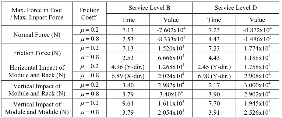
Table 5 shows the reaction forces and impact forces of the racks and modules obtained by nonlinear time history analysis. The maximum normal force between the rack and pool floor is 1.486x10⁵N at 4.43 seconds for Case IV. The normal force at the higher friction coefficient is also found to be larger for both OBE and SSE. The maximum friction force between the pool floor and rack feet is 1.188x10⁵N at 4.33 seconds in Case IV. It can be seen that the horizontal displacement (sliding) of the rack is smaller at a higher friction coefficient. In contrast, the friction force between rack feet and pool floor is larger at a higher friction coefficient in each case of the OBE and SSE. The horizontal impact between the rack and modules occurs several times for all cases and the maximum impact force is 2.908x10⁴ N in Case IV. The vertical impact force between rack and modules is 3.4x10⁴ N for Case II in the bottom module. However, it has the same order of magnitude as those in other cases, and only a slight differences exist between the four cases. The maximum vertical impact force between modules is 2.526x10⁴ N in Case IV.
In the response spectrum analyses as shown in Table 6, Case V and Case VI, the maximum stress ratio is 0.687 and 0.915, respectively. The stress ratios found by the response spectrum analyses are higher than those from the nonlinear time history analysis. Thus, it is confirmed that any damage on the spent fuel storage racks are not expected.
A detailed stress evaluation shows that the maximum von-Mises stress for the base plate of the modules is 10.86MPa in Case III. Figure 6 shows the results of the fuel assembly rattling analysis. As a whole, Case IV, when μ =0.8 and SSE, is judged to be the most severe load condition. In the case of the fuel assembly rattling in the cell pipe, the impact force between the fuel assembly and cell pipe is found to be 1,500 N in Case IV, and the magnitude of the impact force does not seem to affect substantially the dynamic behavior of the entire rack.
(a) SSE (μ=0.2) (b) SSE (μ=0.8)
Stress Evaluation for Plates and Pipes in the Module
Detailed stress analyses have been performed to evaluate the structural integrity of the base plate, pipe reinforcing plate, and cell pipes. The base plate and pipe reinforcing plate are modeled as the perforated plates, and the rigid links are used to simulate the cell pipe. For each of the four cases of time history analyses, 20 different time steps are selected for the detailed stress analyses to have the maximum internal moment of each column end. The four edges are fixed in translational directions, and only the internal moments of the column ends are applied at the four edges of the plate.
To evaluate the fuel assembly rattling phenomenon, the fuel assembly is modeled using a beam element, and the gaps between fuel assembly and cell pipe are modeled using a 3-dimensional combination element in ANSYS. It is assumed conservatively that the gap between the fuel assembly and the cell pipe changes from a maximum of twice the nominal gap to a zero gap. The fuel assembly rattling analyses are performed for four analysis cases using the displacement time histories of the cell pipe bottom end in modules obtained from the seismic analysis. Only the displacement time history for the case of the top module is selected for an analysis because it seems to be more severe than those for other module cases. These displacement time histories are applied at the fuel bottom and cell pipe top, simultaneously.
Table 2: Description of analysis cases
Case Friction Coefficient Type of Earthquake
Service Level
I 0.2 OBE B
II 0.8 OBE B
III 0.2 SSE D
IV 0.8 SSE D
V Response Spectrum Analysis OBE B
VI Response Spectrum Analysis SSE D
Table 3: Maximum displacement of nonlinear time history analysis for racks
Max. Horizontal Disp. Friction Coeff.
Service Level B Service Level D
Time Value (mm) Time Value (mm)
X-Direction μ =0.2 12.79 -2.20 (Foot) 10.24 12.30 (Top) 0.8
μ = 3.63 1.0 (Top) 3.47 -0.771 (Foot)
Y-Direction μ =0.2 12.78 2.23 (Top) 3.65 -11.03 (Top) 0.8
μ= 7.20 0.06 (Top) 8.24 -1.506 (Foot)
Table 4: Maximum stress ratio of nonlinear time history analysis for rack and module
Load combination Friction Coeff.
Spent Fuel Storage Rack Module
Comp. Stress Ratio Comp. Stress Ratio
Service Level B μ =0.2 Rack Foot 0.481 Column 0.343 0.8
μ= Rack Foot 0.497 Upper Beam 0.455
Service Level D μ=0.2 Rack Foot 0.874 Column 0.438 0.8
Time Value Time Value
Normal Force (N) μ =0.2 7.13 -7.602x10
4
7.23 -8.872x10⁴ 0.8
μ= 2.53 -8.333x10⁴ 4.43 -1.486x10⁵
Friction Force (N) μ =0.2 7.13 1.520x10
4
7.23 1.774x10⁴ 0.8
μ = 2.53 6.666x10⁴ 4.43 1.188x10⁵ Horizontal Impact of
Module and Rack (N)
0.2
μ = 4.96 (Y-dir.) 1.268x10⁴ 2.45 (Y-dir.) 1.758x10⁴ 0.8
μ = 6.89 (X-dir.) 2.024x10⁴ 6.98 (Y-dir.) 2.908x10⁴ Vertical Impact of
Module and Rack (N)
0.2
μ = 3.80 2.982x10⁴ 2.17 3.000x10⁴ 0.8
μ = 3.79 3.40x10⁴ 3.90 2.902x10⁴ Vertical Impact of
Module and Module (N)
0.2
μ = 9.64 1.611x10⁴ 7.70 1.945x10⁴ 0.8
μ = 3.79 2.054x10⁴ 3.91 2.526x10⁴
Table 6: Maximum stress ratio of response spectrum analysis for racks
Service Level B Service Level D
Comp. Stress Ratio Comp. Stress Ratio
Outer Column 0.687 Outer Column 0.915
CONCLUSION
The structural integrity of the spent fuel storage racks and modules under a seismic load has been investigated. For this purpose, finite element models were developed and a nonlinear time history analysis was carried out. The weights of the components and OBE/SSE time history inputs at its installing position are used as the load for structural integrity. The maximum value of stress ratio (calculated/allowable stress ratio) is 0.874 at the feet of the rack and 0.455 at the upper beam of the module. That is, the maximum combined stresses due to seismic loads are within the allowable stresses of the ASME NF code. The seismic analysis results show that no damage to the structural integrity is expected. In addition, the numerical results of the nonlinear time history analysis demonstrate that the impact between the rack and the side wall of the pool does not occur. Finally, the spent fuel storage racks and modules have been successfully designed and evaluated. They have been well operated without accident.
ACKNOWLEDGEMENTS
REFERENCES
ANSI/ANS 51.1 (1983). Nuclear Safety Criteria for the Design of Stationary Pressurized Water Reactor Plants, American Nuclear Society.
ASME Boiler and Pressure Vessel Code, Section III (1989). Rules for Construction of Nuclear Facility Components, Subsection NF Supports, American Society of Mechanical Engineers.
NUREG/CR-5912 (1992) Review of the Technical Basis and Verification of Current Analysis Methods Used to Predict Seismic Response of Spent Fuel Storage Racks.
Regulatory Guide 1.29 (1976). Seismic Design Classification, U.S. Nuclear Regulatory Commission. KOPEC (1988). Seismic (Dynamic) Analysis For Reactor Building, Korea Power Engineering Company. Regulatory Guide 1.61 (1973). Damping Values for Seismic Design of Nuclear Power Plants, U.S. Nuclear Regulatory Commission.
Regulatory Guide 1.92 (1976). Combining Modal Responses and Spatial Components in Seismic