Transactions of the 17th International Conference on Structural Mechanics in Reactor Technology (SMiRT 17) Prague, Czech Republic, August 17 –22, 2003
Paper # O04-6
Smart Fibre ‘Bragg Grating’ Feasibility Retrofitting Assessment in Nuclear
Power Plant Structures
Aleksandar M. Zikic
1), Leslie M. Smith
2), Gary L. Brodt
3)1) University of Paisley, Paisley, Renfrewshire, UK 2) British Energy Generation (UK) Ltd, East Kilbride, UK
3) Compass (permanently contracted to British Energy Generation (UK) Ltd.), West Kilbride, UK
Abstract
Monitoring the loads in pre-stressing tendons in the stressed Concrete Pressure Vessel (PCPV) or Pre-stressed Concrete Containment (PCC) of nuclear power stations is an on-going requirement, to ensure that adequate pre-stress could resist imposed loads and maintain structural integrity. Current procedures in unbonded pre-stressing systems rely on the lift-off test to confirm that there is sufficient pre-stress in the pre-stressing tendons.
Internationally, a significant number of nuclear power plants have now been operating for a period in excess of twenty years and some for more than thirty years. As a result, interest in the management of the ageing of civil engineering structures has received a higher priority than was hitherto the case in order to confirm or extend the operational life of nuclear power plants. The ability to monitor the pre-stress in pre-stressing tendons using Smart Fibre ‘Bragg grating’ technology in a real time environment, would augment the available information that civil engineers require to confirm the continued fitness for purpose of critical structures. It would also allow continuous monitoring of the strains experienced at key points of an instrumented pre-stressing tendon. However, prior to any full-scale installation of an instrumented pre-stressing tendon, it is necessary to conduct a feasibility study and identify a suite of tests to confirm that the fragile fibre optic cable installed along a length of pre-stressing tendon, would survive the installation process and the environmental conditions in service.
This paper describes the feasibility study and set of tests conducted to ascertain if it is possible to install a fibre optic instrumented cable along a length of pre-stressing tendon. The paper identifies several of the areas that required investigation to ascertain whether a fibre optic sensor would survive the installation, tensioning and de-tensioning processes associated with pre-stressing tendons.
PRE-STRESSING - WHAT IS IT AND CAN IT BE MEASURED CONTINUOUSLY?
The pre-stressing equipment in a PCPV is used to contain the operational pressure experienced in an Advanced Gas Cooled Reactor (AGR), a Magnox reactor or the structural performance of a containment building. The tendons are contained within ungrouted ducts, which allow in-service replacement. Pre-stress is achieved through the use of 18-mm Dyform strands that form pre-stressing tendons. The normal configuration of the pre-stressing tendon is seven strands each made of seven wires per strand.
Currently it is difficult to provide long-term, real-time monitoring of the pre-stressing forces at the anchorages of tendons, the variation of strain distribution along the pre-stressing tendons and variation of loading of the pre-stressed tendons as functions of time although the structural performance of pre-stressed concrete pressure vessels (PCPVs) and pre-stressed concrete containment (PCC) is dependent upon the maintenance of adequate levels of pre-stress within the concrete.
Current pre-stressing experience indicates that tendon load changes with time, due to many factors [1]. It is understood that the greatest losses occur in the first two years. As documented on a tendon pre-stressing web site, ‘when doing repairs on 30-year old stress-relieved strands, the strand will not ‘un-relax’ when it is de-tensioned’ [2]. Similarly, if the strand is spliced and re-tensioned, there will not be any more relaxation in the original strand. There will be some amount of relaxation in the new strand of the splice. It is understood that tendon strands are not repaired, spliced or re-tensioned in the PCPVs or PCCs. The reason for reporting the above findings is to indicate the need for understanding the elongation and creep characteristics of the tendon strand. Creep and relaxation of steel, while related, are not the same thing. Relaxation is the loss of load under constant strain, while creep is the change in length under constant load. Relaxation of load will occur as a result of creep, but creep is not necessarily indicated simply because relaxation has taken place. Relaxation may have been caused as a result in the creep of the concrete due to the pre-stressing. However, the concrete creep can largely be ignored in “old” vessels .
Currently Available Technology
gauges along a length of tendon strand to measure load variations along the strand at key points. This technique will only identify the variation of strain at the points of instrumentation. The third technique is to install a load cell at both anchorages with logging equipment to continuously monitor any changes in load on a pre-stressed strand. Like the first technique, this method only identifies the loading details at the anchorage points.
Conventional instrumentation techniques using strain gauges are limited to a one-to-one point-by-point measurement. Each instrument requires a separate set of connection wires routed back to the measurement equipment, thus severely limiting the number of points that can be monitored. This is less than ideal when measuring critical areas that are large, or difficult to instrument due to their physical location [3].
The application of strain gauge technology to the tensioning tendons in a PCPV or PCC in connection with the measurement problem is not practical, even with a very limited number of sensors, due to the harsh environment that connecting wiring would experience during installation. Strain gauge technology and wiring, if mounted along the surface of a strand prior to installation, would be subjected to the friction of installation that would strip the instrument and wiring from the strand.
Final assessment of the above three techniques has one additional drawback, none of these techniques incorporate any instrumentation for the confirmation of any change in length of the instrumented strand.
New Proposed Technology
The use of optical fibre sensors to measure strain or combined strain and temperature is the proposed technology to be recommended to resolve the strain measurement problem. It is also proposed, in later stages of testing, that a separate length of uninstrumented fibre optic cable be installed along an instrumented strand so that an OTDR (Optical Time Domain Reflectometry) could be used to measure any change in length of the strand during test periods thus aiding the separation of creep and relaxation.
The use of directly engraved Bragg gratings on optical fibre sensors in strain or combined strain and temperature measurements started to emerge about ten years ago. During this period research resulted in the development of different materials suitable for this purpose and a better understanding into the related mechanisms that make the whole technique feasible. Currently, growing availability of both the sensors and the processing equipment make this technique of stress/strain measurements more popular in the monitoring of various structures including applications in complex civil engineering [4, 5]. The size of the instrumented fibre (0.125 mm in diameter) and the possibility of having multiple sensors on the same fibre make this technique attractive for retrofitting on existing structures as well as incorporating into new designs [5, 6]. A score of bonding agents that are used to bond strain sensors to various materials are known to exist from strain gauge manufacturers’ sheets, but poorly if at all described in optic fibre sensor references.
The principle advantage of Bragg gratings is that the measured information is wavelength-encoded (an absolute value), therefore making the sensor self-referencing, rendering it independent of fluctuating light levels and the system immune to source power connector losses that plague many other types of optical fibre sensors [7]. Additional benefits with using fibre optic sensors are their immunity to electromagnetic interference (EMI), their lightweight, their flexibility, stability, high temperature tolerance, and durability against high radiation environments [7].
The strain response of the grating arises from the physical elongation of the sensor and the temperature response arises from the inherent thermal expansion of the fibre material and the temperature dependence of the refractive index. Once the Bragg grating sensors have indicated temperature and/or strain, it is necessary to demodulate these values into their component parts [8, 9]. Research has been conducted to indicate that it is possible to have up to 3 superimposed gratings at the same location and still approach ~100% reflectivity [10]. This may indicate that it is possible to inscribe one grating to monitor the strain characteristic changes along a section of fibre and one grating to monitor the temperature characteristics. Both gratings would be inscribed at the same location.
Several research papers have reported success in the use of fibre Bragg gratings in civil structure installations. The ability to install fibre optic sensing systems on civil structures that can monitor both static and dynamic loads has been reported in connection with pre-stressing tendons that are subject to a tensile strain of around 8,000 µstrain. Measurements have been reported to have accuracy in the order of ± 0.15mm. The environment was harsh in terms of high moisture and large temperature excursions, with the optical fibres being subjected to rough handling. The fibre Bragg gratings although being embedded directly in composite materials consisting of carbon fibre composite pre-stressing tendons had an 83% survival rate after construction of the precast girders. Resolution of tendon strain was reported to be in the order of a few µstrains [11]. Measurements were reported to represent the stress relief in the deck tendons associated with ‘combined effects of de-stressing, concrete shrinkage, creep, dead-loading of the bridge deck, and post-tensioning of the two spans’.
Problems To Be Resolved To Allow Use Of The New Technology
The elastic properties of the fibre optic instrumented cable had to be compatible to the steel tendon strand. It was expected that the tensioning process will exert a strain of 5,900 to 8,100 µstrains on the tendon strand and due to the helicoidally configured tendon strand, the fibre optic cable would experience a proportionally different amount of strain - between 6,000 to 8,250 µstrains. The applied force was expected to be static during the course of the pre-stressing period.
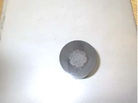
Figure 1 - The polished cross sectional sample of tendon strand – note grooves between adjacent wires.
Desk studies were completed to determine how the Bragg gratings will be used to determine strain and temperature along a helix of a strand and how the measured values can be used to represent the strain of the strand. Desk studies were completed to ascertain how Bragg grating technology has been used in similar civil engineering projects to measure strain and temperature, how it was mounted and the relationship of that work to the current study.
The fibre optic cable must be bonded into the groove of the strand by an adhesive that can also withstand the applied loading. It was not an option to redesign the seven-wire tendon strand with the king wire being an instrumented composite ‘wire’ surrounded with six steel wires. Therefore, the technique for application of the adhesive and the fibre optic cable must be capable of ensuring that the fibre optic cable sets down below the strand outer surface along the entire length of the strand groove. It would be also necessary to protect the free tail ends of fibre optic cable, where the fibre optic cable is connected to measurement instrumentation.
The application of the adhesive and preparation of the surface of the tendon strand, protection of the tendon strand after instrumentation, the curing of the adhesive and protection of the fibre optic free tail ends during the bonding stage and the evaluation of special jigs needed for bonding the fibre to the tendon strand was considered.
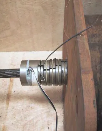
A simulated test jig was manufactured to allow safe tensioning of experimental lengths of a tendon strand. The test pieces needed tensioning to the same loads that an installed strand would experience and the fibre optic tails must be monitored during the process to verify continuous optical integrity. The free tail ends were routed through the split in the de-stressing spacers and not through the barrel and wedge assemblies that are normally used to lock off pre-stressing strands.
Figure 2 - The free tail ends routed through the de-stressing spacers.
DESK STUDY OF FIBRE OPTIC AND BONDING AGENTS:
Fibre Optic Desk Study
Desk study in connection with the Bragg grating demonstrated the ability to write a periodic change in the core index of refraction in a single-mode optical fibre provides a selective mirror for the wavelength that satisfies the Bragg condition. The periodicity of the Bragg grating is altered when the section of fibre is affected by local strain on the fibre core. This alteration to the index of refraction due to strain tunes the selective mirror to one and only one wavelength of light. The method of operation of a Bragg grating relies on the transmission of broadband light down the fibre optic cable. This band of light must be broad enough to cover the full extent of Bragg grating sensitivity of all Bragg gratings within the instrumented fibre optic cable. If there are multiple Bragg gratings along the fibre optic cable, there will be one reflected frequency of light for each Bragg grating. The gratings used in sensor applications typically have bandwidths of 0.05 to 0.3nm [7]. The reflected beams of light can then be detected by instrumentation for each Bragg grating located along the length of instrumented fibre and any deviation of the respective wavelength from its nominal value will be associated with a corresponding variation in strain/ temperature. Different tunable filters are used to measure the returned light, with a resolution of ±1 µstrain achievable.
In the simplest form, a fibre Bragg grating consists of a periodic modulation of the refractive index in the core of a single-mode optical fibre [6]. Bragg’s law states the maximum intensity of the reflected ray occurs when sin θ = nλ/2d, where n is an integer, θ is the Bragg angle (the complement of the angle of incidence), λ is the wavelength of the beam of energy and d is the separation between planes.
In the fibre optic core that has Bragg gratings inscribed, the Bragg condition is met when λB = 2neffΛ. Where λB is the Bragg grating wavelength (the free space centre wavelength of the input light that will be back-reflected from the Bragg grating), neff is the effective refractive index of the fibre core at the free space centre wavelength, and Λ is the period (the interval of spacing between successive Bragg gratings).
The dependence of the grating wavelength response to externally applied forces, such as temperature and strain is that property of the Bragg grating that is being studied in this research project. The measurement of the exact wavelength of the reflected light allows the strain or temperature of the fibre at that location to be determined. Strain and temperature sensitivity affecting the shift in the Bragg grating centre wavelength is given by the following formula:-
∆λB = 2((Λ(∂neff/∂l) +neff(∂Λ/∂l))∆l + 2((Λ(∂neff/∂T) +neff(∂Λ/∂T))∆T (1)
The first term (2((Λ(∂neff/∂l) +neff(∂Λ/∂l))∆l) represents the strain effect on an optical fibre [7], [12]. The second term (2((Λ(∂neff/∂T) +neff(∂Λ/∂T))∆T) represents the effect of temperature on an optical fibre [7], [12]. Deconvolution of the constituent parts is necessary to establish measurement of temperature and strain.
Adhesive Desk Study
materials and the selection and availability of various adhesives that fell into the acceptable criteria of types of suitable bonding adhesives.
There were three adhesives selected from the Dexter-Hysol range of adhesives. Their selection was the result of having the following specifications; Resistance to water and petroleum products, adequate tensile strength specifications, available in small containers for use, maximum service temperature and acceptable working life.
Objectives
1. Can a fibre optic cable be bonded to a Dyform Tendon?
2. Are the elasticity characteristics of the bonding agent compatible with those of the fibre optic cable and those of the Dyform tendon?
3. Will the installation process of the Dyform Tendon compromise the bonding of the fibre optic cable to the tendon? 4. Will the welding procedure during the installation phase of the replacement Dyform Tendon damage the bonding,
the Bragg gratings or the fibre optic cable?
Desk study and pre-test research findings
Preparation of the Dyform tendon strand should include degreasing, cleaning with etching agents, priming of the steel prior to the adhesion process and post bonding protection. The concerns associated with the fibre optic cable during the bonding and post bonding process centred on the protection of the free tail ends. Elasticity characteristics of Dyform tendons in relationship to the fibre optic cable and bonding agents were theoretically possible from the results of the desk study. The knowledge of the installation process of Dyform tendon provided sufficient information to assist the research team to devise techniques for bonding and protecting the fibre optic cable and the free tails, that proved successful during the trial testing period.
The study of a possible damage to fibre optic cable during installation process of the tendon concentrated around the barrel and wedge assembly area. The key to the success of the whole research project was the survivability of the fragile fibre optic cable free tail ends the rest of the fiber being sufficiently protected by both steel and the adhesive inside the groove. Two techniques were attempted, with the second technique producing the best results.
Heat transfer of welding installation process demonstrated that the welding process would not harm any written Bragg gratings or the integrity of the adhesive. However, the research team recommended that mechanical connection devices would be more appropriate for replacement of an installed Dyform tendon strand with an instrumented strand, due to less mechanical handling.
Test Set-up
The research into bonding provided sufficient information to produce procedures for the preparation of the fibre optic cable and tendon strand using two different techniques. Two 1.5-metre lengths of Dyform tendon strand were chosen from a previously used strand, removed from lengths of pre-stressing tendons at a PCPV installation. Both lengths of strand were de-greased with trichlorethene using rags, immediately washed with de-ionized water 1 pt/wt wash and then dried. The chosen grooves (2 per strand) that were to receive the adhesive and a length of un-instrumented fibre optic cable ( of the same specification as an un-instrumented fibre would be), , were then cleaned with a 400 grit grinding wheel (small Drimmel tool type). The prepared strand was then washed with Concentrated HCL 1 pt/wt and immediately washed with de-ionized water 1 pt/wt wash and dried. A proprietary primer suitable for the adhesive and steel was then applied to the prepared strand to prevent any corrosion. The fibre optic cable was de-greased with trichlorethene using rags. During the preparation phase, the test team wore surgical gloves to prevent oils on the skin to recontaminate the clean surfaces.
¼ - bridge strain gauges were bonded to opposite sides of the mid-point of the Dyform tendon strand and on both barrels on opposite ends of the test jig. Each strain gauge was monitored over the course of the entire stressing period and also during the course of the weeklong stress to confirm the loading applied and any de-loading that occurred during the course of the test. The length of both test tendons was 304 kN and was applied in 50 kN stages with a small period of settling in between the stages. A Laser light pen for fibre optic cable testing was used to confirm the integrity of the fibre cable bonded to the Dyform tendon strand. There were two separate tests conducted on two lengths of Dyform strand. The first test consisted of stressing the prepared tendon strand, monitoring the test assembly, stressing the tendon strand, and inspection of the test strand. The second strand underwent the same stressing and stressing stages, but was allowed to remain under the initial 304 kN load for one week prior to a lift off test and de-stressing. The second test incorporated one different adhesive and one adhesive that passed the first test. The results from both tests are provided in the following section:
Summary of Test Results:
instrumented tendon strand used in the first test proved unsatisfactory as both of the tails of the fibre optic cable were damaged during installation. The damage of the free tail ends resulted in the development of a different method of protecting the fragile fibre optic tail so that chances of survival during the second test would be higher. The mounted strain gauges confirmed that the test piece underwent the applied strain. It should be noted that the testing also confirmed that the cyanide-acrylate adhesive used for bonding the strain gauges to the strand and barrels was capable of surviving the loads applied.
The failure of the adhesive during test one was considered to be associated with a lower than acceptable work-life of the adhesive (20-minutes) for preparation purposes. During the bonding preparation of both strand samples, it was necessary to rotate the strands, apply the adhesive and pull the fibre optic cable into the groove – all at the same time. This manual process took a period of time, which may have exceeded the work lifetime (pot-life) of the adhesive. The adhesive that passed during the first test (Dexter Hysol 9433) had a work-life of 40 minutes. Of all three adhesives that were tested, the failed adhesive also had the lowest tensile strength (19.3 MPa).
During test two, both adhesives passed (Dexter Hysol 9433 and 0151) as well as the fibre optic cable and the strain gauge bonding adhesive for the duration of the extended test period. Testing confirmed that unloading did take place after the removal of the hydraulic tensioning equipment. The measured readings dropped immediately from ~+6,500 µstrains to ~+5,100 µstrains. These readings were recorded using the strain gauges mounted along the helix of the tendon strand as measured by instrumentation. A Lift-Off test (load check) was conducted at the end of the one-week extended test during test two, to confirm the amount of unloading. The readings taken using the lift-off test were 238 kN, 239 kN and 239 kN representing a loss of 22% of the original loading, which is in good agreement with the above strain measurements for this type of measurement (refer to Tables 1.1 and 1.2). During further trials, this reduction in load will be compensated by immediately re-shimming the tendon strand under test prior to any extended test period. Test two preparations during the installation phase of the prepared tendon strand experienced no damage to the free tail ends, as a result of the modified preparation arrangement.
DISCUSSION
The desk study has reviewed published papers that indicate that fibre Bragg grating technology has been installed into new construction and also retro-fitted into existing civil structures along lengths of pre-stressing wire. These papers report that the technology did measure strain/stress and creep in the civil structure. Therefore in theory and practice it is possible to use this new technology to measure stress along a Dyform tendon strand.
The installation practices observed at the PCPV site require modifications in line with the testing phase of this research to prevent compromising the fibre optic cable.
Existing lock off barrel and wedges require no modifications. However, modifications would be necessary to the de-tensioning spacers.
Installation practices used during the replacement stage of an installed Dyform tendon strand identified two methods. One practice requires the use of a clamp to attach the replacement Dyform tendon strand and the second method welds the replacement strand to the existing strand. Neither technique would compromise a fibre optic cable installed on the strand of the replacement cable; however, the connection piece option is preferred as it requires simpler and fewer operations.
Testing during this stage of the research demonstrated that bonding of the fibre optic cable to a Dyform strand was possible and that at least two adhesives are suitable for this purpose.
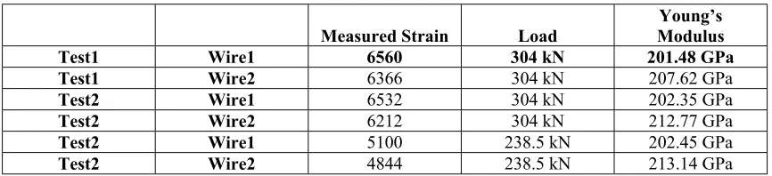
Testing demonstrated that the elasticity characteristics of the fibre optic cable and two of the three chosen adhesive bonding agents were suitable to the characteristics of the Dyform tendon within the limits of the applied strain. Tables 1 and 2 provide results of the measured strain, load and Young’s Modulus from test one (wire 1) and test two (wire 2) [13].
Table 1
Measured Strain Load Modulus Young’s
Test1 Wire1 6560 304 kN 201.48 GPa
Test1 Wire2 6366 304 kN 207.62 GPa
Test2 Wire1 6532 304 kN 202.35 GPa
Test2 Wire2 6212 304 kN 212.77 GPa
Test2 Wire1 5100 238.5 kN 202.45 GPa
Table 2
Average Longitudinal Strain Strand Young’s modulus
Test1 6463 205.4 GPa
Test2 6372 207.43 GPa
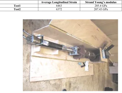
Figure 3 - The test set-up.
CONCLUSIONS
With the success of the experimental results from the reported testing, a series of tests are proposed using instrumented fibre optic cable to confirm that strain and temperature results obtained from a length of instrumented fibre will register the same as the strain gauges and temperature sensors ( to be decided upon ) installed during the further testing. Lessons learned will be applied to the new series of tests.
In principle it is possible to use new SMART technology to measure the load distribution along a length of non-composite Dyform tendon strand. The success of future testing will confirm that in practice fibre optic measurements will provide a new tool for the civil engineers monitoring stress/strain in PCPV and PCC structures.
REFERENCES
1. Nuclear Research Index (NRI) issue number 1.5.12, sub issue number 1.5.12.3. 2. Pre-stressing Technology Institute Website Message Board
3. Dill M.J. et al. “Monitoring concrete structures using fiber optics,” Concrete, Sept./Oct. 1993.
4. Culshaw B., et al., “Smart Structures and Applications in Civil Engineering,” Proc. of IEEE, vol. 84, No.1, 1996, Page 78.
5. Udd E., “Fiber Optic Smart Structures,” Proc. of IEEE, vol. 84, No. 1, 1996, Page 60.
6. Spillman W., Jr, “Sensing and Processing for Smart Structures,” Proc. of IEEE, vol. 84, No.1, 1996, Page 68. 7. Othonos, A. et al., “Fiber Bragg Gratings (Fundamentals & Applications in Telecommunications & Sensing),”
Artech House, ISBN 0-89006-344-3; circa 1999.
8. Derickson D., "Fiber Optic Test and Measurement", Prentice Hall, 1998.
9. Davis M. A., et al., “All-Fibre Bragg Grating Strain-Sensor Demodulation Technique using a Wavelength Division Coupler,” Elect. Letters, vol. 30, No 1 pp 75- , 1994.
12. Meltz, G., et al. “Bragg grating formation and germanosilicate fibre photosenditivity," International Workshop on Photoinduced Self-Organization Effects in Optical Fibre, Quebec City, May 10-11, SPIE Proceedings, vol 1516,pp. 185-199, 1991.