Analytical Methods to Estimate the Crack
Width in RC Beams
Arvind 1, Dr. Narendra H 2
Research Scholar, Department of Civil Engineering, M.S.Ramaiah Institute of Technology, Bangalore, Karnataka,
India1
Associate Professor, Department of Civil Engineering, M.S.Ramaiah Institute of Technology, Bangalore, Karnataka,
India2
ABSTRACT: An analytical investigation was carried out to study the cracking behaviour of RC beams in various conditions. A total of 58 beams previously casted by various different researchers were adopted for this study. Parameters such as varying cover of concrete, grade of steel, grade of concrete were observed. The expressions given by different code books were inspected. The variation of the above parameters given by different code books were compared with experimental data. Such a comparison gave us a clear picture of the accuracy of each expression. The different codes except ACI estimated the crack width close to the experimental values for moderate and low exposure covers of 20 and 30 mm. In beams having higher concrete covers a gross under estimation was observed. ACI over estimated the crack width for lower covers and was agreeable to experimental values for covers of 40 mm. A similar comparison with respect to variation in grade of steel also was done and it was found that ACI over estimates the effect of grade of steel and other equations under estimate it. The expression given by the Indian code was considered for the second phase of the thesis, the drawbacks of this expression were noted down and certain modifications were suggested. The formula now agrees well with the experimental results.
KEYWORDS: Crack width, Flexural Cracks, Serviceability.
I.INTRODUCTION
Crack width is a criteria falling under the limit state of serviceability and can be addressed as a durability issue. Literature suggests that this phenomenon has been studied since as early as 1950’s and yet the estimation of width of flexural cracks still eludes researchers. A review of literature reveals that numerous researchers have been interested in this phenomenon and have suggested various expressions to estimate the width and spacing of flexural cracks. It is to be noted however that none of the expressions are similar to each other nor are they completely accurate. Experimental
investigations [i], statistical approaches [ii] etc have been already tried with no promising results. In this research
program, 58 beams casted by various researchers were considered for the study. The crack width estimation was done for this using the expressions given by Indian, American, Egyptian, European and Chinese codes. The results of the above calculations were compared with the experimental values. The different parameters affecting the prediction of each of this expression were studied and a modification was suggested to the IS-456 expression.
II. CRACK WIDTH ESTIMATION USING SOME OF THE BUILDING CODES.
2.1 IS-456:2000
With usual notations as specified in the code.
x
h
C
a
a
w
cr m cr cr
min
2
1
2.2 ACI 318
With usual notations as specified in the code.
2.3 EN 1992
sm cm
r
k
S
w
,max
With usual notations as specified in the code.2.4 ECP 203:2007
With usual notations as specified in the code.
2.5 GBJ 10-89
W max= 1.41 * Ѱ * (fs/Es) *[(2.7 * c) + (0.11Φ)/ρte)]ϒ with usual notations as specified in the code.
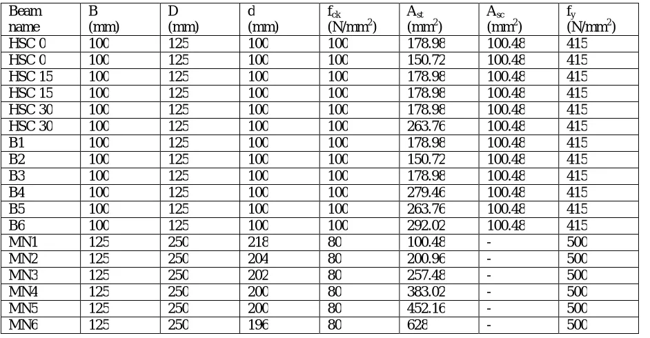
III. PROPERTIES OF THE BEAMS CHOSEN FOR THE STUDY Table 3.1: Property of beams having a clear cover of 20mm Beam
name
B (mm)
D (mm)
d (mm)
fck
(N/mm2)
Ast
(mm2)
Asc
(mm2)
fy
(N/mm2)
HSC 0 100 125 100 100 178.98 100.48 415
HSC 0 100 125 100 100 150.72 100.48 415
HSC 15 100 125 100 100 178.98 100.48 415
HSC 15 100 125 100 100 178.98 100.48 415
HSC 30 100 125 100 100 178.98 100.48 415
HSC 30 100 125 100 100 263.76 100.48 415
B1 100 125 100 100 178.98 100.48 415
B2 100 125 100 100 150.72 100.48 415
B3 100 125 100 100 178.98 100.48 415
B4 100 125 100 100 279.46 100.48 415
B5 100 125 100 100 263.76 100.48 415
B6 100 125 100 100 292.02 100.48 415
MN1 125 250 218 80 100.48 - 500
MN2 125 250 204 80 200.96 - 500
MN3 125 250 202 80 257.48 - 500
MN4 125 250 200 80 383.02 - 500
MN5 125 250 200 80 452.16 - 500
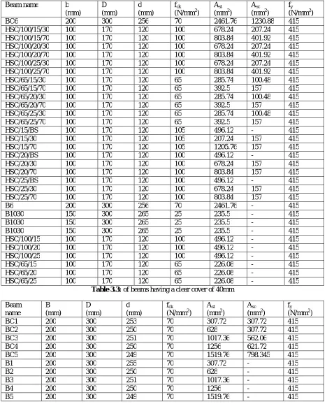
Table 3.2: of beams having a clear cover of 30mm
Beam name b
(mm) D (mm) d (mm) fck
(N/mm2)
Ast
(mm2)
Asc
(mm2)
fy
(N/mm2)
BC6 200 300 256 70 2461.76 1230.88 415
HSC/100/15/30 100 170 120 100 678.24 207.24 415
HSC/100/15/70 100 170 120 100 803.84 401.92 415
HSC/100/20/30 100 170 120 100 678.24 207.24 415
HSC/100/20/70 100 170 120 100 803.84 401.92 415
HSC/100/25/30 100 170 120 100 678.24 207.24 415
HSC/100/25/70 100 170 120 100 803.84 401.92 415
HSC/65/15/30 100 170 120 65 285.74 100.48 415
HSC/65/15/70 100 170 120 65 392.5 157 415
HSC/65/20/30 100 170 120 65 285.74 100.48 415
HSC/65/20/70 100 170 120 65 392.5 157 415
HSC/65/25/30 100 170 120 65 285.74 100.48 415
HSC/65/25/70 100 170 120 65 392.5 157 415
HSC/15/BS 100 170 120 105 496.12 - 415
HSC/15/30 100 170 120 105 207.24 157 415
HSC/15/70 100 170 120 105 1205.76 157 415
HSC/20/BS 100 170 120 100 496.12 - 415
HSC/20/30 100 170 120 100 678.24 157 415
HSC/20/70 100 170 120 100 803.84 157 415
HSC/25/BS 100 170 120 100 496.12 - 415
HSC/25/30 100 170 120 100 678.24 157 415
HSC/25/70 100 170 120 100 803.84 157 415
B6 200 300 256 70 2461.76 - 415
B1030 150 300 265 25 235.5 - 415
B1030 150 300 265 25 235.5 - 415
B1030 150 300 265 25 235.5 - 415
HSC/100/15 100 170 120 100 496.12 - 415
HSC/100/20 100 170 120 100 496.12 - 415
HSC/100/25 100 170 120 100 496.12 - 415
HSC/65/15 100 170 120 65 226.08 - 415
HSC/65/20 100 170 120 65 226.08 - 415
HSC/65/25 100 170 120 65 226.08 - 415
Table 3.3: of beams having a clear cover of 40mm Beam name B (mm) D (mm) d (mm) fck
(N/mm2)
Ast
(mm2)
Asc
(mm2)
fy
(N/mm2)
BC1 200 300 253 70 307.72 307.72 415
BC2 200 300 250 70 628 307.72 415
BC3 200 300 251 70 1017.36 562.06 415
BC4 200 300 250 70 1256 621.72 415
BC5 200 300 249 70 1519.76 798.345 415
B1 200 300 255 70 307.72 - 415
B2 200 300 250 70 628 - 415
B3 200 300 251 70 1017.36 - 415
B4 200 300 250 70 1256 - 415
IV. ANALYTICAL STUDIES.
The above presented beam properties were used as input to calculate the width and spacing of cracks using different code equations and were compared with experimental values of crack width. Such a investigation clearly gave a picture of the randomness in the estimation of crack width by the various expressions. Further, the variation of crack width with increase in clear cover, grade of steel and grade of concrete were also noted. The IS 456 formula for estimating the crack widths was put into scrutiny and certain points of interest were observed.
V. RESULTS AND DISCUSSION
5.1 Initial observations
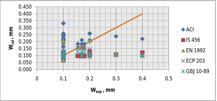
A simple comparison of the crack widths estimated by the different expressions and the experimentally obtained data shows us that there is a wide scatter of results. The error at certain points is too high and a consistent under or over estimation is visible with certain expressions. For example, the American expression (ACI 318) always over estimates the crack width for lower values of concrete cover or grade of steel while the Indian standard as well as the other expressions under estimates it as shown in figure 5.1, 5.2, 5.3.
Figure 5.1.1: Estimation of crack width using different formulas compared with expt. data for 20 mm cover.
Figure 5.1.2: Estimation of crack width using different formulas compared with expt. data for 30 mm cover.
0.000 0.050 0.100 0.150 0.200 0.250 0.300 0.350
0 0.05 0.1 0.15 0.2 0.25 0.3
Wca
l
, m
m
Wexp , mm
ACI
IS 456
EN 1992
ECP 203
GBJ 10-89
0.000 0.050 0.100 0.150 0.200 0.250 0.300 0.350 0.400 0.450
0 0.1 0.2 0.3 0.4 0.5
Wca
l
, m
m
Wexp, mm
ACI
IS 456
EN 1992
ECP 203
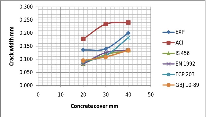
Figure 5.1.3: Estimation of crack width using different formulas compared with expt. data for 40 mm cover. In order to better understand the variation in crack width for different concrete covers the following graph was plotted. These values in the graph are the average crack width values for a particular cover.
Figure 5.1.4: Average crack width v/s Concrete cover for different code equations.
5.2 Analytical Investigations
5.2.1: Tension stiffening effect.
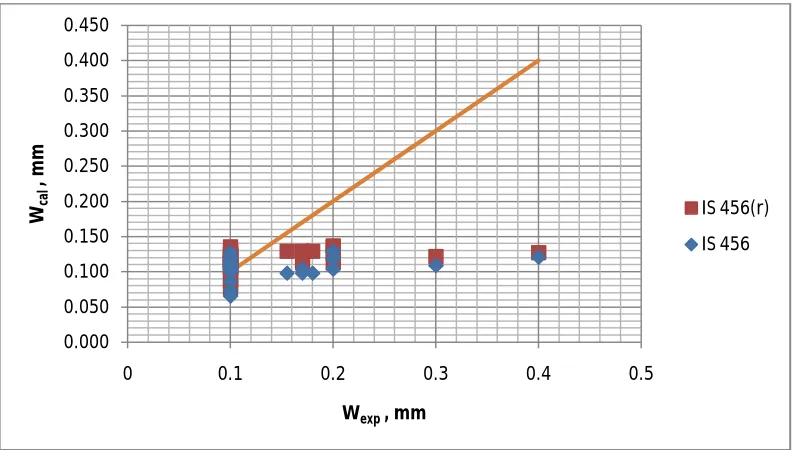
The IS 456 gives an expression which takes into effect the tension stiffening effect. Researchers now believe that since the stress in the steel is high and there is a huge difference in the tensile strength of steel and concrete, the tension stiffening effect can be ignored. The figures 5.2.1, 5.2.2, 5.2.3 compare the original estimations of IS 456 and the revised estimations IS 456(r) with the experimental value.
0.000 0.050 0.100 0.150 0.200 0.250 0.300 0.350 0.400 0.450
0 0.05 0.1 0.15 0.2 0.25 0.3
Wca
l
, m
m
Wexp, mm
ACI
IS 456
EN 1992
ECP 203
GBJ 10-89
0.000 0.050 0.100 0.150 0.200 0.250 0.300
0 10 20 30 40 50
C
ra
ck
w
id
th
m
m
Concrete cover mm
EXP
ACI
IS 456
EN 1992
ECP 203
Figure 5.2.1: Comparison of crack width with and without tension stiffening effect with experimental values for C=20mm.
Figure 5.2.2: Comparison of crack width with and without tension stiffening effect with experimental values for C=30mm.
0.000 0.050 0.100 0.150 0.200 0.250 0.300
0 0.05 0.1 0.15 0.2 0.25 0.3
Wca
l
, m
m
Wexp , mm
IS 456(r)
IS 456
0.000 0.050 0.100 0.150 0.200 0.250 0.300 0.350 0.400 0.450
0 0.1 0.2 0.3 0.4 0.5
Wca
l
, m
m
Wexp, mm
IS 456(r)
Figure 5.2.3: Comparison of crack width with and without tension stiffening effect with experimental values for C=40mm.
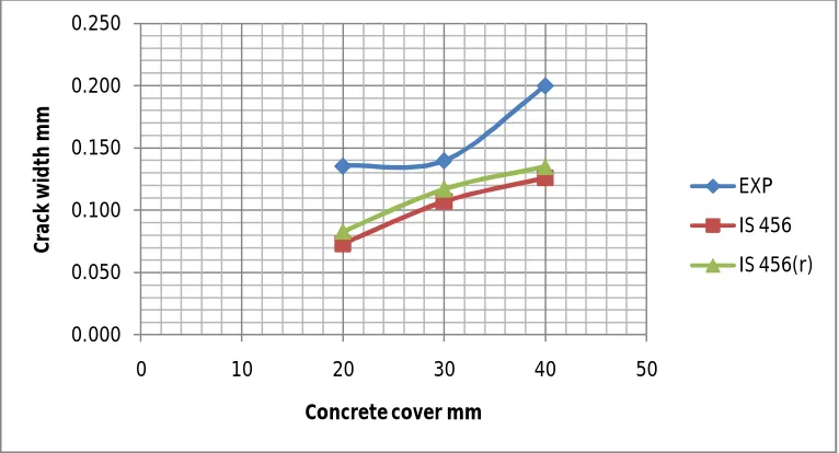
The following graph is obtained by plotting the average values of crack width for different concrete cover with and without tension stiffening effect. The series named as IS 456 gives the average values of crack width obtained from the original expression while the series named IS 456(r) gives us the average values of crack width obtained without the tension stiffening effect.
Figure 5.2.4: Average crack width v/s concrete cover with and without tension stiffening effect.
0.000 0.050 0.100 0.150 0.200 0.250 0.300
0 0.05 0.1 0.15 0.2 0.25 0.3
Wca
l
, m
m
Wexp, mm
IS 456(r)
IS 456
0.000 0.050 0.100 0.150 0.200 0.250
0 10 20 30 40 50
C
ra
ck
w
id
th
m
m
Concrete cover mm
EXP
IS 456
5.2.2 Modification to Moment at working load (Mw):
Table 5.2.1 gives details of twelve experimentally casted and tested beams. Details such as experimental ultimate moments are compared to the theoretical ultimate moments and a coefficient of variation is found out. This helps us in recognising the fact that the working moment that we consider for determining the stress is lower experimentally calculated. Bearing this in mind, the average value of coefficient of variation is multiplied to the obtained value of
theoretical working moment (Mw) and the stress in steel is determined by this value. The revised values of crack width
so obtained are compared with the original values given in IS 456 and with experimental values.
Beam no Muth
(kN-m)
Mwth
(kN-m)
Muexp
(kN-m)
Mwexp
(kN-m)
Muexp/ Muth
(kN-m)
HSC 0 5.98 3.98 9.75 6.5 1.63
HSC 0 5.10 3.4 11.78 7.85 1.53
HSC 15 5.98 3.98 8.125 5.42 1.35
HSC 15 5.98 3.98 12.18 8.12 2.04
HSC 30 5.98 3.98 8.53 5.68 1.42
HSC 30 8.48 5.65 12.18 8.12 1.44
B1 5.98 3.98 8.125 5.42 1.35
B2 5.10 3.4 8.53 5.68 1.67
B3 5.98 3.98 7.72 5.12 1.29
B4 8.91 5.94 10.96 7.31 1.23
B5 8.48 5.65 8.93 5.95 1.05
B6 9.26 6.17 8.53 5.68 0.92
Average = 1.41
Observing the above table it is evident that the variation in the theoretical and the experimental values of ultimate and hence working moment is almost 50%. Incorporating this input and estimating the widths of the cracks using the IS 456
equation for the revised values of working moment (Mw) and comparing it with the original values graphs were plotted.
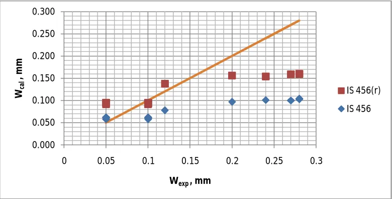
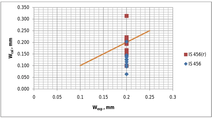
Fig 5.2.5, 5.2.6, 5.2.7 represent the comparison of original crack width values along with the modified values compared with the experimental values.
Figure 5.2.5: Comparison of crack width for normal and modified ‘Mw’ values when C=20mm.
0.000 0.050 0.100 0.150 0.200 0.250 0.300
0 0.05 0.1 0.15 0.2 0.25 0.3
Wca
l
, m
m
Wexp , mm
IS 456(r)
Figure 5.2.6: Comparison of crack width for normal and modified ‘Mw’ values when C=30mm.
Figure 5.2.7: Comparison of crack width for normal and modified ‘Mw’ values when C=40mm.
The following graph fig 5.2.8 was plotted between average values of crack width and concrete cover. The series named as IS 456 gives the values of average crack width v/s concrete cover for the original code expression. The series named
IS 456(r) gives the values of average values calculated with modified value of working moment ‘Mw’ against concrete
cover.
0.000 0.050 0.100 0.150 0.200 0.250 0.300 0.350 0.400 0.450
0 0.1 0.2 0.3 0.4 0.5
Wca
l
, m
m
Wexp, mm
IS 456(r)
IS 456
0.000 0.050 0.100 0.150 0.200 0.250 0.300 0.350
0 0.05 0.1 0.15 0.2 0.25 0.3
Wca
l
, m
m
Wexp, mm
IS 456(r)
Figure 5.2.8: Average value of crack width v/s concrete cover for normal and modified Mw values.
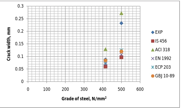
5.2.3 Grade of steel:
Beams having the same cover but different grade of steel were chosen for this study. Fig 5.2.9 clearly shows the variation in the width of the cracks for fe 415 and fe 500 steel. It also shows the extent to which such a variation can be estimated by the different code expressions.
Figure 5.2.9: Grade of steel v/s average crack width as estimated by different code books and compared with the experimental values.
0.000 0.050 0.100 0.150 0.200 0.250
0 10 20 30 40 50
C
ra
ck
w
id
th
m
m
Concrete cover mm
EXP
IS 456
IS 456(r)
0 0.05 0.1 0.15 0.2 0.25 0.3
0 100 200 300 400 500 600
C
ra
ck
w
id
th
, m
m
Grade of steel, N/mm2
EXP
IS 456
ACI 318
EN 1992
ECP 203
VI. CONCLUSIONS
The current analytical study was carried out to study and compare the different code equations in use, also to study the sensitivity of certain parameters in the expressions and relate it to experimental data. The main objective of this study was to suggest a simple and effective way to improve the accuracy of the IS 456 expression in use. A few conclusions drawn from this study are as follows
1.) The predictive abilities of all the expressions used so far are questionable as the deviation from the
experimental data is too high and the agreement with other each other is very low.
2.) American expression over estimates the width of the cracks almost in all cases and the other expressions under
estimate it.
3.) This might be because the American suggested expression is a direct function of steel stress and the other
expressions use the value of the stress in steel only to calculate the strains.
4.) Ignoring the tension stiffening effect although increases the accuracy in the IS 456 expression but, the
percentage increase is small.
5.) When a factor of 1.5 is multiplied to the working moment obtained, the accuracy of the expression is far
higher and the values are very close to the experimental values. This suggests that the stress in longitudinal steel at the stage of working load is higher than estimated by our deductions.
6.) Since the stress in steel depends on the term ‘modular ratio’, which in turn depends on the modulus of
elasticity of both steel and concrete , a more precise method to estimate the same is in order. Also, the modular ratio obtained by the INDIAN Standards is low because the code predicts a rather higher value of modulus of elasticity of concrete.
7.) Literature suggests that a better way is available to predict the stress in steel using computer computation
capabilities, when such a technique is perfected, the prediction of stress in steel will be of higher accuracy and a better value of crack width shall be obtained.
8.) Although, width of the crack is very sensitive to concrete cover as shown by graphs above, it is still seen that
as the prediction of stress in steel increases in accuracy the expressions estimate more precisely for any change in cover.
9.) When the grade of steel used increases, the resultant increase in crack width is quite high, but such a steep
increase is not recorded by any expression other than the ACI 318.
10.)This is because for fy 500 steel, the stress at working load predicted by all the codes lie in the range of 300
N/mm2 but the American code predicts a stress of 350 N/mm2. This is mainly due to the high modular ratio,
the effect of which is prominent as the grade is increased. This observation again proves that the stress in longitudinal stress is by far the most important parameter.
ACKNOWLEDGEMENT
We sincerely thank management, CE, Principal and Head of Department of M.S.Ramaiah Institute of Technology, Bangalore-560054, affiliated to VTU, Belgaum for the facility provided to conduct the experimentation and all the technical guidance.
REFERENCES
1. Florian Barth, Robert J Frosh, Control of cracking in concrete structures, ACI committee 224R, 2001
2. Said M Allam et al , Crack width evaluation for flexural RC members , Department of structural engineering, Alexandria university, may 2012. 3. S H Chowdhury et al, A new formula for prediction of crack widths in reinforced partially pre stressed concrete beams, school of engineering, Griffith University Queensland, Australia, 2001.
4. B B Broms, Crack width and crack spacing in reinforced concrete members, Journal of American Concrete Institute 62 (10) (1965) 1237-1256 5. Reka Nagy, Structural cracking of reinforced cracking members, BME dept of construction materials and Engineering geology, Second conference of Junior researchers in civil engineering, 2014.
6. Wakchaure M.R et al, Effect of concrete cover on crack width of RC beams, Elixir international Journal, 47(2012) 8782-8785.
7. Jianmin Zhou, Calculation methods of the crack width and deformation for concrete beams with high strength steel bars. Front. Struct. Civ. Eng.2013 ,7(3): 316-324
9. Hwamin Lee, The crack width calculation program for structural concrete members based on a limit state design, Springer science, 10.1007/978-94-017-8798-7_90, 2014.
10. Nobuyuki Yamato et al, Prediction method of crack width and spacing in reinforced concrete based on bond analysis, 14th world conference on earthquake engineering, Beijing, China, 2008
11. Amir Soltani et al, Crack opening behaviour of concrete reinforced with high strength reinforcing steel, International journal od concrete structures and materials, Vol 7 No.4 pp253-264, 2013.
12. Syed Yasir Alam et al, Measuring crack width and spacing in reinforced concrete members, HAL, hal id- hal-00683652, May 2010. 13. N Subramanian, Controlling the crack width of flexural RC members, Indian Concrete Journal, 2005.
14. Building Code requirements for reinforced concrete, ACI 318-95 and commentary ACI 318R-95, American Concrete Institute, Detriot, 1995 15. Building Code requirements for reinforced concrete, ACI 318-05 and commentary ACI 318R-05, American Concrete Institute, Detriot, 2005 16. Eurocode-2, Design of concrete structures- Part I: General rules and rules for buildings 1992-1, European committee for standardisation, October 2001, Belgium.
17. The Egyptian code for design and construction of reinforced concrete structures, ECP 203-2007 , Ministry of Housing , Egypt. 18. Indian Standard for plain and reinforced concrete-code of practice, IS 456:2000, Bureau of Indian Standards.