SMiRT 20-Division 6, Paper 2005
1
Structural Analysis towards Erection of Prototype Fast Breeder Reactor
Components
Bhuwan Chandra Sati, V. Balasubramanian, P. Chellapandi and S. C. Chetal
Nuclear Engineering GroupIndira Gandhi Centre for Atomic research, Kalpakkam,India. [email protected]
Keywords: PFBR, erection of components, lifting spiders, component handling
1. ABSTRACT
PFBR is a sodium cooled pool type reactor. The normal operating temperature is 397 0C for its cold pool components and 547 0C for the hot pool components. The hot pool and cold pool are separated by an inner vessel. The entire primary sodium pool is contained in a 25 mm thick main vessel of 12.9 m diameter and 13 m height. The main vessel is surrounded by a safety vessel which is still larger than the main vessel. The reactor has a design life of 40 years. So, works such as fabrication and erection of the large components are key activities for the construction of PFBR. The life of reactor is dependent on the structural integrity of these large components in both normal and accidental conditions. In view of this the fabrication and erection activities connected with PFBR have to be performed with high quality and safety requirements. In this paper the erection sequence and methodologies adopted for the various reactor assembly components such as main vessel, safety vessel etc are brought out. The SV has already been erected
2. INTRODUCTION
In PFBR higher safety restrictions are called for in view of the radiation hazards involved during operation as repairs and rectifications for the primary sodium circuit components is not possible. The large thin components are manufactured with very tight tolerances. Hence good care is essential to avoid errors and damage to the parts during erection. Also the functionalities and specification of the PFBR components are different from conventional industrial components, specialized techniques for erection are required. In PFBR the safety vessel and main vessel are to be place in a pit type reactor vault, having very narrow gap between the vessel and the vault. Since the components are thin shell structure and cannot be repaired once erected special attachments and handling fixture are designed for the erection. The components are analysed for the loads occurring on them during handling process.
In this process the safety vessel (diameter 13.5 m and 16 m height) has already been erected successfully on the inner reactor vault within a gap of 70 mm. The further erection of components is planned and mockups are performed where ever needed.
3. ERECTION METHODOLOGY
The vessels and other structures are unique to the PFBR. The functional and quality requirements are also different from the conventional industries. The vessels are large diameters thin shell structure and are to be placed in narrow gaps. The erection of components and the construction of reactor building have to be carried out simultaneously. So the erection and constructional methodologies are planned in advance. The narrow gaps and the limited space calls for the tight tolerances in construction. Or the erection procedure for the components asks for new attachments and equipment.
Normally spiders are attached to the thin shell structures to retain their shape within tolerable deformation. It planned to erect the components with minimum attachments, so to reduce the risk of damage to the components. Special attachments and handling spiders are designed to handle the vessels. The vessels are handled without attached stiffening spiders.
SMiRT 20-Division 6, Paper 2005
2
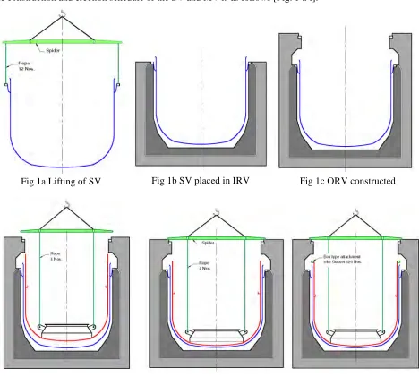
The ropes will be connected to a spider at the top and subsequently to the crane hook. Then the spider will be supported on the top of the outer reactor vault (ORV). The MV will be kept hanging.
While hanging from the ORV, a box type ring will be attached to the MV top portion with 126 vertical stiffeners. The MV will then be lifted through the box type ring with 126 rods attached to it. The rods will pass through the sleeves present in ORV. The load of the MV will then transferred to the rods and the spider will be removed, to facilitate the erection of the Grid plate, thermal baffle, MV cooling pipes, primary pipes and inner vessel in the MV.
Finally the roof slab will be brought to the RV and fixed on the ORV. The MV along with the internals will be lifted further to bring in position to the roof slab and welded to it. To carry this operation, the lifting spider of the MV will again be brought back on the top of ORV. The spider will be placed on 24 jacks. The MV will be attached to the spider through four ropes attached to the lugs attached to the CSS. Finally the MV will be lifted by the jacks and welded to the roof slab.
4.
ERECTION SCHEDULE
The construction and erection schedule of the SV and MV is as follows [Fig. 1 a-l]:
Fig 1b SV placed in IRV Fig 1c ORV constructed
SMiRT 20-Division 6, Paper 2005
3
5.
ANALYSIS OF ATTECHMENTS AND SPIDERS
Since the MV and SV are large size thin shell structure and should not undergo any plastic deformation during erection. For safe handling the lifting spiders and attachments needs to be checked for the loads occurring on them during following operations:
• Transport of SV and MV to site from site assembly shop
• Lifting of SV through 12 lugs along with the spider
• Lifting of MV through four ropes attached to lugs on CSS
• Lifting of Assembly (MV, CC, CSS, GP, IV and primary piping) through 126 rods
• Lifting of MV along with internals through four ropes attached to lugs on CSS
The Spiders are made of carbon steel (IS 6062 material). For the parts which are coming in contact of the austenitic stainless steel, SS is used. The material properties are obtained from RCC-MR-2007 for the respective material. Philosophically margin is applied to loads and the allowable stresses to take care the uncertainties at the site.
To adequately transport the safety vessel from site assembly shop to reactor vault location a base frame is designed and the safety vessel is supported on this base frame through 4 vertical supports and support blocks. Stress analysis of the base frames, for transporting SV and MV from site assembly shop to RV location, has been done to verify the support carrying capacity and to find the deflection levels at the loading points. For easy and safe transport the maximum deflection are limited to less than 25 mm to meet the site constraints.
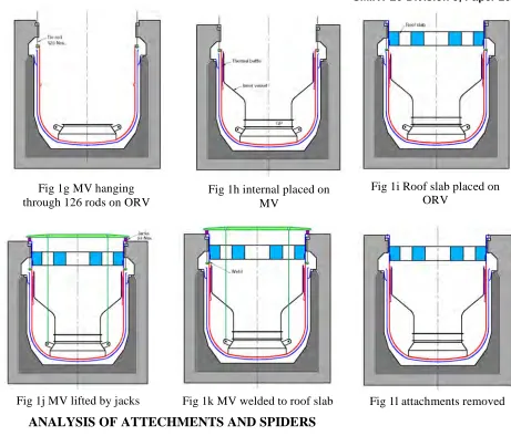
Inner diameter of SV is fixed as 13.5 m. Self-weight of SV 155 t. The SV support is a box type flange with upper and lower plate connected with stiffeners (B. C. Sati et al, 2006). The lugs for lifting the SV are designed such that the load of the SV gets transferred with both top and bottom plate of the flange to avoid bending of the plates [Fig. 2]. A lifting spider is designed to facilitate the vertical lifting of the safety vessel i.e. the lifting lugs are connected to spider with vertical ropes [Fig. 3]. The safety vessel is analysed
Fig 1j MV lifted by jacks Fig 1k MV welded to roof slab Fig 1l attachments removed Fig 1g MV hanging
through 126 rods on ORV
Fig 1h internal placed on MV
SMiRT 20-Division 6, Paper 2005
4
for erection load with six lifting lugs. The stresses on the different parts are limited within the elastic limit (yield stress), thus avoids any plastic deformation [Fig. 4]. However, considering possible uncertainties in load distribution in the actual site condition twelve supports are recommended. The radial deflections at the conical support to safety vessel junction are also found to be small (< 0.4 mm), which are insignificant. Hence there is no requirement of putting spider at that location during erection.
Two designs are considered, one with single point lifting at the centre and another with four point lifting. Based on ease of manufacturing the design with four point lifting is suggested [Fig. 3]. The spider is made of 12 radial beams which are interconnected by tangential beams. The beams are made of ISMB 600 with additional plates in some sections to increase the rigidity. The SV has already been erected [Fig. 5].
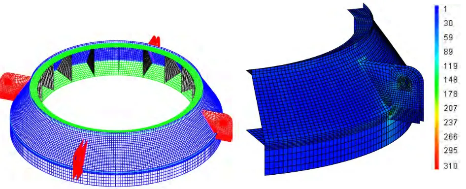
MV is 12.9 m diameter and 25 mm thk vessel with dished end and without any penetration. It is carrying about 2200 t load during operation of the reactor. It is subjected to axial load through out its life. It is intended to have axial attachment on the MV for handling it to avoid any risk of circumferential defect. While the MV is hanging during the erection of its internal components the supporting attachments are subjected to about 500 t. So to hold the MV 126 vertical stiffeners are attached to it [Fig. 6]. Two shells are attached to the gussets to have torsion rigidity, as the MV is thin plate structure with open at top. The shells are connected with a base plate which will be used for attaching lifting rods. While holding in position the MV bends inwards at the top causing compressive hoop stress. To reduce hoop stress and avoid risk of buckling a top plate is attached to MV with stitch weld. MV is very flexible and it bends inwards the load get concentrated at the bottom part of the stiffener. To reduce the stress at that location a thin base plate is attached at the bottom of the stiffener. It is also attached to MV with stitch weld. The location of rods thus the width of stiffener is governed by the site conditions. The height of the stiffeners and shells are optimized base on site condition and stress in different parts of the attachment. A sector of 2.86º is analysed using CASTEM FEA software. The stresses are limited within the elastic limits [Fig. 7]. The maximum radial inward deflection of MV is 2 mm at the top edge. As the support structure is used for suspending MV
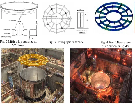
Fig.5 Successful erection of safety vessel on the inner wall of reactor vault Fig. 2 Lifting lug attached at
SV flange
SMiRT 20-Division 6, Paper 2005
5
through tie rods only during installation of internals the deflection does not pose any concern. The buckling analysis of 180º sector has been carried out and it is found that there is no concern of buckling in MV.
The lifting spider of the MV is made in two parts. First, the central part made of four cross beams connected by square beams. Second, a circular channel made by two plates connected by a web plate is attached to the above cross beams. Then 24 box type radial arms are attached to the channel. The arms are joined with the channel with 150 mm diameter pin, so as to facilitate little adjustment for jack positions [Fig. 8]. The spider will be used for lifting and placing the MV inside the SV. Then the spider will be placed on the ORV and MV will be hanging through it. The spider will be subjected to a load of about 200 t of MV and core support structure. The spider will again be used for lifting the MV with internals to be welded with the roof slab and during this process the spider will be subjected to 500 t loads. One fourth symmetric sector of the spider is analysed for the loads during above conditions. The stresses are limited within the elastic limits [Fig. 9].
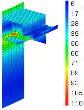
To lift MV four lugs are welded to core support structure. The lugs are made in two plates of 50 mm thickness [Fig. 10]. The plates are also joined with stiffening plate at the top and bottom. The lugs and the CSS are checked for the maximum load of 500 t. One fourth sector of the structure is used for analysis. The shear stresses at the lug to CSS joint and over all stresses on the lugs are checked critically and are found to be in elastic limits [Fig. 11].
Fig. 6 Structure attached to MV for hanging on ORV during erection of internals
Fig. 7 Von mises stress distribution MV lifting attachment
SMiRT 20-Division 6, Paper 2005
6
6.
CONCLUSION
The erection schedule for the major components for PFBR is planned. Special handling attachments and spider are designed and analysed. It is tried to minimize the no. of attachments to the vessels thus avoid the risk of defects on them. ON main vessel axial gussets are attached to avoid risk of circumferential defect. The erection of the large diameter thin vessels is planned without the stiffening spiders. The deflection and stresses on the handling attachments and on the vessels are limited within the elastic limit to avoid any plastic deformation in the erection stage.
REFERENCES
1.IS 2062: 1999, steel for general structural purposes – specification.
2.RCC-MR-2007, Design and construction rules for components of FBR nuclear islands, 2002. Fig. 10 Schematic of core support structure
with four lugs