SEISMIC QUALIFICATION TESTS OF SELECTED TYPES OF RELAYS,
USED IN KOZLODUY NPP
Pavel Spassov
1, Marin Jordanov
2, Boyko Nikolov
31Mechanical engineer, EQE Bulgaria AD, Sofia ([email protected]) 2Structural and seismic engineer, EQE Bulgaria AD, Sofia 3Electrical engineer, EQE Bulgaria AD, Sofia
ABSTRACT
The main objective of the study was to qualify the existing equipment at Kozloduy NPP for seismic event, corresponding to the Revue Level Earthquake (RLE) for the site. This paper is devoted to the Seismic Qualification tests of selected ten types of relays.
The seismic qualification process comprised the following steps:
1. Review of the safety related relays and selection of the types to be qualified;
2. Development of specification for the Seismic Qualification procedures, including functional tests of the relays before, during and after the seismic excitation;
3. Performance of the specified Seismic Qualification; 4. Analyses of the results, conclusions and proposals.
Basic activities in step one included the minimization of the list of the relays to be qualified, considering their safety functions. Various type relays as a function have been selected and included in the test program.
The Required Response Spectra (RRS) were developed on the bases of the RLE for the site of the NPP. The Amplified Response Spectra (ARS) included the effects of amplification of the motion by the response of the structure, as well as the amplification due to the supporting conditions inside the cabinet or equipment. The functional performance of the relays during the seismic excitation was monitored for the following modes: non-operating, operating and transition.
The results of the tests have shown that some certain types of the tested relays are not properly designed from earthquake engineering point of view and should not be used in the safety systems.
INTRODUCTION
The seismic qualification of the old design relays is part of project devoted to qualification of the important for the safety equipment in existing NPP. The electrical and control equipment was subject to test qualification, because of missing proper qualification data and relatively easy achievable qualification by test. In the frame of the project four groups of C&I and electrical equipment were selected for tests. They are relays, motor control centers, differential pressure transmitters and secondary devices for the same transmitters. The selection was done according equipment importance for the plant safety and its quantity in the safety systems. The qualification was performed taking into account international codes and standards for this type of equipment, especially IEEE standards and European documents.
The relays used in WWER-440 units at Kozloduy NPP perform safety functions as actuation of safety systems, and provision of signals and alarms for shift operators’ support.
SELECTION AND DESCRIPTION OF THE TESTED RELAYS
Relays involved in the interlocks of the plant critical safety functions; The total quantity of the different models;
All types of relays to be represented in the test;
Test two samples per model. This decision was taken in order to have more than one sample to check the repetitiveness of results and to have a third spare one in case of failure of the sample, and in order not to reduce the number of different types to be tested (if three units per type had been considered, only 6 different ones could have been tested
The range of the relays subjected to test included ten different models, which belong to four principle types – auxiliary relays, time relays, over-current relays and under-voltage relays. All of them are Russian design and production.
The relay models initially scheduled for testing were as follows (2 units per model): Auxiliary relays, type РП23УХЛ4
Auxiliary relays, type РП-251 Auxiliary relays, type РП8УХЛ4 Auxiliary relays, type РПУ-1-362 Auxiliary relays, type РП25УХЛ4 Time relays, type TX12ZN
Time relays, type ВЛ-34УХЛ4
Time relays, type ЭВ142У4
Over-current relays, type РТ-40/0.2У4 Under-voltage relays, type PH-54/320
TEST FACILITY AND EQUIPMENT
Test facility is located in Steel Structures Research Laboratory of the University of Architecture, Civil Engineering and Geodesy, specialized in seismic research of structures in Sofia, Bulgaria.
The seismic excitation in horizontal direction is performed by means of a shaking table with a mounting surface of 1.5 by 1.5 m. This is a two component shaking table (horizontal translation in one direction and rotation about a vertical axis). It is used for a single axis testing in both horizontal axes (X and Y respectively). For vertical axis tests, one of the actuators is mounted in a vertical position. The attached to the piston road platform has a size of 1.00/1.00m. The drive mechanisms for both shaking tables are servo-controlled, electro-hydraulic actuators, manufactured by Instron Ltd. They have the following capabilities given in Table 1.
Table 1. Shaking table basic characteristics
Frequency Range 0-100 Hz
Dynamic Load Capacity 50 kN
Maximum Stroke 50 mm
Maximum Velocity 270 mm/sec
Maximum Acceleration 10 g
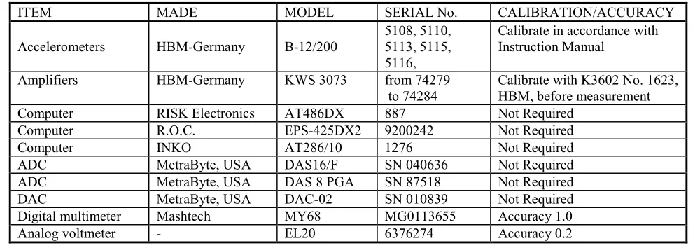
Table 2. Testing equipment
ITEM MADE MODEL SERIAL No. CALIBRATION/ACCURACY
Accelerometers HBM-Germany B-12/200 5108, 5110, 5113, 5115, 5116,
Calibrate in accordance with Instruction Manual
Amplifiers HBM-Germany KWS 3073 from 74279
to 74284 Calibrate with K3602 No. 1623, HBM, before measurement
Computer RISK Electronics AT486DX 887 Not Required
Computer R.O.C. EPS-425DX2 9200242 Not Required
Computer INKO AT286/10 1276 Not Required
ADC MetraByte, USA DAS16/F SN 040636 Not Required
ADC MetraByte, USA DAS 8 PGA SN 87518 Not Required
DAC MetraByte, USA DAC-02 SN 010839 Not Required
Digital multimeter Mashtech MY68 MG0113655 Accuracy 1.0
Analog voltmeter - EL20 6376274 Accuracy 0.2
TEST METHOD
For the purposes of the seismic qualification corresponding test specification and test procedure were developed.
The seismic qualification tests were performed separately for the three components of the seismic excitation in X, Y and Z directions. Two levels of excitation are required: an Upper level corresponding to Safe Shutdown Earthquake(SSE) and a Lower level corresponding to Operating Basis Earthquake(OBE). A set of accelerograms corresponding to the Required Response Spectra are generated. The synthetic time histories have 40 sec duration with 20 sec strong motion part. The signals for the movement of the shaking table correspond to the generated accelerograms. The Test Response Spectra (TRS) are obtained for the recorded accelerograms of the shaking table movement. For comparison of the RRS and TRS their graphs are presented on the figures 1 and 2. All Response Spectra are for 5% damping.
The relays were mounted on a rigid platform in their normal service position. Supporting base frame is rigidly anchored to the shaking table by welding. Each one of the devices is fastened to the rigid platform by bolts.
The tested relays were mounted on the shaking table for horizontal excitation, first in X direction and second in Y direction. For excitation in Z direction they are mounted on the platform for vertical vibration.
TESTING PROGRAM
The Seismic Qualification Program included the following activities: Preliminary visual inspection of the integrity of the specimens;
Functional testing for electrical functionality verification before seismic tests; Mounting on the shaking table;
Seismic qualification tests with monitoring of the selected signals for contacts’ chatter; Visual inspection and functional tests after the completion of the seismic tests;
TEST CONDITIONS
Two test levels corresponding to 5% damping factor were defined, considering the floor response spectra (FRS), which were increased to take into account the local amplification of the panels, due to various supporting conditions inside the cabinets or equipment. The FRS were based on the Review Level Earthquake (RLE), officially required for the seismic evaluation of the plant. Additionally, a Local Earthquake (LE) effect was considered. The tests in every direction were performed by three excitations at Lower level for seismic aging and followed by three excitations at higher level corresponding to Safe Shutdown Earthquake (SSE). During each series of excitation, the behavior of the tested equipment is monitored in three modes. The first mode corresponds to non-operating (de-energized state).The second mode required operating state (energized coils). The last one is the transient mode, during which change of state is introduced to the tested relays.
Particular requirements concerning test conditions for each type of relay are stated in the detailed Test Specification. For all of them the requirements according IEEE C37.98 standard were applied, taking into account specific way of their actuation and design.
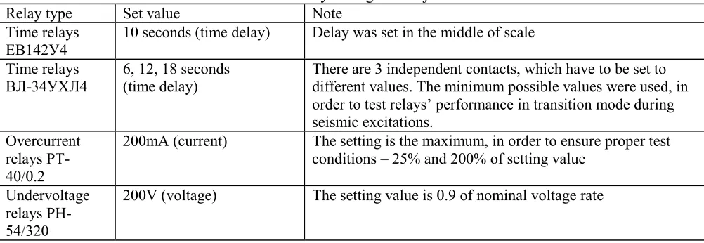
Three type of relays have to be set before start of seismic test program – time relays (all types), over-current and under-voltage relays. The set values are shown in the following table. They were not changed during execution of seismic test program, with exception for under-voltage relays. The setting and adjustment values are presented in Table 3.
Fig.1. Response spectra TRS and RRS, OBE and SSE levels, X and Y direction of testing
Table 3 Relay settings and adjustment
Relay type Set value Note
Time relays ЕВ142У4
10 seconds (time delay) Delay was set in the middle of scale
Time relays ВЛ-34УХЛ4
6, 12, 18 seconds (time delay)
There are 3 independent contacts, which have to be set to different values. The minimum possible values were used, in order to test relays’ performance in transition mode during seismic excitations.
Overcurrent relays РТ-40/0.2
200mA (current) The setting is the maximum, in order to ensure proper test
conditions – 25% and 200% of setting value
Undervoltage relays РН-54/320
200V (voltage) The setting value is 0.9 of nominal voltage rate
Electric power supply is separated in four circuits. One loop for 220V supplies AC auxiliary and over-current relays. The second one is for 220V DC auxiliary and time relays. The third loop supplies 110V DC auxiliary relays. The last one ensures variable AC power supply for undervoltage relays using separate transformer.
For testing purposes 32 monitoring channels, split in two groups were used. During seismic tests only one group was monitored because of the limitation of the data acquisition system, so two identical excitations were performed in each stage in order to register performance of all relays.
FUNCTIONAL TEST BEFORE SEISMIC EXCITATIONS
Mechanical check
All relays were checked for mechanical damages, possible because of the improper storage, handling and transportation. No any damages were observed. After visual inspection they were mounted on the test facility. Their mechanical functionality was examined, applying nominal voltage/current to the coils. The change of state was checked using two methods: visually observing mechanical behavior and monitoring electrical signal from the contacts.
Two types time relays ВЛ-34УХЛ4 and TX12 could not be checked visually. All relays changed state properly.
After first functional test, time relays TX12 did not return back to their normal position. Because of this, it was impossible to perform seismic tests on this type relays.
Electrical check
According test specification auxiliary relays powered by AC (РП-25УХЛ4) have to be checked for pick up at 0.8 nominal voltage. Both of them picked up. Drop out voltage is also measured.
Time relays were checked for time delay.
Pick up and drop out voltage of under-voltage relays at 0.9Un (200V) setpoint were checked and recorded in the protocol.
FUNCTIONAL TEST AFTER SEISMIC EXCITATIONS
Following test specification, complete functional tests were performed in order to check the condition of tested equipment after completion of the seismic testing program.
Mechanical check
All relays were checked for mechanical damages. The relays kept their structural integrity. No problems with anchorage to test facility of the relay boxes were observed also. Their mechanical functionality was examined, applying nominal voltage/current to the coils. The change of state was checked exactly in the same way as in the test before seismic excitation.
All tested relays changed state properly.
Electrical check
According test specification, the auxiliary relays powered by AC (РП-25УХЛ4) have to be checked for pick up at 0.8 nominal voltage. Both of them picked up. Pick up and drop out voltage is registered. Practically there were no variations from initially measured values.
Time relays were checked for time delay. Initially measured time delays were confirmed.
Pick up and drop out voltage of under-voltage relays at 0.9Un (200V) setpoint were checked and recorded in the protocol. Very small deviations were registered.
In addition electric insulation tests of relays were performed. Insulation was measured between contacts, coil-ground and metal components-ground. All relays pass the test – the insulation was more than 400M at 1000V voltage applied.
No any mechanical damages and malfunctions induced from seismic excitations were registered. All relays after completion of seismic test program worked properly and their electrical parameters are identical with initially measured parameters.
Conclusion about seismic aging of relays
The tested relays were no destroyed by applied excitations. They keep their integrity and functionality unchanged, so they can perform reliable operation after seismic event.
FUNCTIONAL TESTS DURING SEISMIC EXCITATIONS
Data acquisition system acquires monitoring channels using sampling rate of 1000samples/second for each channel. Voltage applied to monitored contacts is 5VDC and 8VDC.
Deviations from test specification
DC relays РП251 operated at 90-98% nominal voltage, test specification requirement is 100% nominal voltage (conservative).
All other DC relays operated at 93-96% nominal voltage, test specification requirement is 100% nominal voltage (conservative).
AC auxiliary relays РП-25 in operating mode were supplied with 100% nominal voltage, instead of 80% according test specification (non-conservative).
Over-current relays РТ40/0.2 worked in operating mode at 235% of set current value - test specification requires 200%. In non-operating mode current was 27% of setting – requirement is for 25%. (conservative in operating mode)
Tests in X direction
Non-operating mode: Closed contacts of relays PT-40 and PH-54 chattered in both excitation levels. Prompt contacts of time relays ЭB142 chattered also in both levels. Closed contacts of time relays ВЛ34 chattered at 30% (voltage varied between 70-100% continuously during excitations). All other relays pass the test.
Operating mode: Closed contacts of relays PT-40 and PH-54 chattered in both excitation levels. Signals from time relays ВЛ34 and prompt contacts of time relays ЭB142 were inadequate (possible bad contact of the circuits). All other relays pass the test.
Transition mode: Signals from time relays ВЛ34 and prompt contacts of time relays ЭB142 were inadequate (possible bad contact of the circuits). All other relays changed state properly. Nevertheless, the problems with closed contacts in both states (non-operating and operating) of under-voltage and over-current relays remained.
Tests in Y direction
Non-operating mode: Closed contacts of relays PT-40 and PH-54 chattered in both excitation levels. Prompt contacts of time relays ЭB142 chattered also in both levels. Closed contacts of time relays ВЛ34 chattered at 15-20% (voltage varied between 80-100% continuously during excitations). All other relays passed test.
Operating mode: Closed contacts of relays PT-40 and PH-54 chattered in both excitation levels. Extremely high chattering of PT-40 contacts was observed. One of auxiliary positioning relays РП-8 chattered 3 times at high excitation level. Signals from time relays ВЛ34 and prompt contacts of time relays ЭB142 were inadequate (possible bad contact on the circuits). All other relays passed test.
Transition mode: Signals from time relays ВЛ34 and prompt contacts of time relays ЭB142 were inadequate. Bad connection was found in relay ВЛ34 circuit after test at high excitation level, test was repeated and relays passed test successfully. Relays РП-8 was switched twice because of the operator fault, however they changed state properly following control signal. All other relays changed state properly. Nevertheless, the problems with closed contacts in both states (non-operating and operating) of under-voltage and over-current relays remained.
Tests in Z direction
Non-operating mode: Closed contacts of relays PT-40, PH-54 and prompt contact of time relays ЭB142 chattered in both excitation levels. At low excitation level they opened only once. One of the relays РП-23 chattered at high level. The same relay was inspected and adjusted after the test. The test was repeated and this relay passed test successfully. All other relays passed test.
Operating mode: Extremely high chattering of over-current relays PT-40 contacts was observed. One of under-voltage relays PH-54 chattered at high excitation level.
Transition mode: All relays changed state properly. Nevertheless, the problems with closed contacts in both states (non-operating and operating) of under-voltage and over-current relays remained.
Summary about Functional Performance during Seismic Event
connection and were rewired for individual control of monitored contacts. The final results are as reported below.
Over-current relays РТ-40 and under-voltage relays РН-54 chatter in all three investigated directions in both states – operating and non-operating. They do not have reliable performance even in low excitation levels. This behavior was not surprising taking into account their specific design and way of actuation.
Snap action contact of one relay ЭB142 failed in one horizontal and in vertical direction of testing in non-operating mode. Time delay contacts of the same type relays did not experience any failure.
One normally closed contact of time relays ВЛ34 chattered in all tested directions. Three other normally closed contacts of the same relays chattered also in X direction of the testing. So, 4 of total 12 monitored contacts of this type of relays failed in X direction.
The time relays TX12 performed reliably in all tests.
All time relays operated exactly without variation of preset time delays.
Auxiliary relays РП8, РП23, РП25, РП251 and РПУ1 performed reliably without any failure.
CONCLUSIONS
All auxiliary relays involved in the seismic qualification test demonstrated reliable operation, keeping the required state of all contacts, as well as prompt change of contacts position in transition mode.
Two out of three types of time relays experienced some problems with instant or delayed contacts.
Over-current as well as under-voltage relays did not keep their contacts closed not only during high excitation levels, but at low level as well.
No closure of opened relay contacts is registered. So, all monitored problems are allocated to closed contacts. Therefore no one relays armature had changed position during seismic tests.
In transition mode all relays changed their state properly.
After seismic tests all tested relays keep reliable operability, without changing settings and electrical parameters.
The tested auxiliary relays have robust design, and due to it no single contact chatter or other component failures were registered. The time relays with exception of one type TX12ZN experienced some problems, mostly with instant contacts and some normally closed contacts, as well. So, in any specific case, it is recommended to perform seismic test or to use supplier prequalified equipment with corresponding certificates.
Mechanical over-current and under-voltage relays which has old design, like tested РТ-40 and РН-54, could not be seismically qualified, because of their inherit vibration vulnerability. Their adjustment of setpoint, relies on very light and precise balance between electromagnetic force from one hand and fine spring on the other. Such design could not involve seismic stability of relays’ contact system. It is recommended that the relays of these types to be replaced in nuclear power plants, situated at seismic regions.
REFERENCES
1. US Nuclear Regulatory Commission, Regulatory Guide 1.100, Seismic Qualification of Electric and Mechanical Equipment for Nuclear Power Plants, 1988;
2. IEEE Std C37.98-1987 IEEE Seismic Testing of Relays;
3. IEEE Std 344-1987 Recommended Practice for Seismic Qualification of Class 1E Equipment for Nuclear Power Generating Stations;
5. International Standard CEI/IEC 68-3-3/1991 Environmental Testing. Part 3: Guidance. Seismic Test Methods for Equipment;
6. Development of Required Response Spectra for the Seismic Qualification of Electrical and Instrumentation Components for Kozloduy NPP, Units 1-4, Empresarios Agrupados International S.A. 7. Test Specification for Relays Seismic Qualification, Report 4401-R-01, Issue 1, EQE Bulgaria, June
1999;