Emission Analysis in Multi-Cylinder SI
Engine Using Catalytic Coated Piston
K. Parthiban1, K.Pazhanivel2
Assistant Professor, Department of Mechanical Engineering, Thanthai Periyar Govt. Institute of Technology, Vellore,
Tamil Nadu, India1
Associate Professor, Department of Mechanical Engineering, Thiruvalluvar College of Engineering and Technology,
Vandavasi, Chennai, Tamil Nadu, India2
ABSTRACT: Internal combustion engines generate undesirable emissions during the combustion process. The
emissions exhausted into the surroundings pollute the atmosphere and harmful to human beings. The emissions are CO, HC, NOX, CO2 etc… In the present investigation, an attempt has been made to control the emissions by coating
metal oxide over the top of piston. The coating is being done by using vacuum coating unit over the piston top. The results obtained from the experiments using the metal oxide coated over the pistons were analyzed. [4] The emission control achieved by adopting this technique was found effective.
KEYWORDS: Multi-cylinder, SI Engine, Catalytic converter, Piston.
I. INTRODUCTION
The strong and stringent air pollution regulations on emission standard provide serious challenges for automobile manufacturers. During the past decades, extensive research has been carried out to decrease the emission of toxic components of combustion gases. Considerable development has been made in fulfilling the standards in the recent years.
The new combustion systems and new technologies contribute to these achievements. In-cylinder treatment can be performed by coating metal oxides on the top of the piston using vacuum coating machine.
II. EXPERIMENTAL SETUP
Five gas analyzers were used for the measurement of HC, CO, NOX and CO2. Experiments were initially carried out on
the engine in order to provide base line data. The engine was stabilized before taking all measurements subsequently. The experiments were repeated by keeping different catalyst coated filter in the exhaust. A multi cylinder Four Stroke Petrol Engine was used. Engine details are given in Table-1.
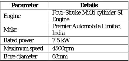
Table -1: Engine Specification
Parameter Details
Engine Four-Stroke Multi cylinder SI
Engine
Make Premier Automobile Limited,
India
Rated power 7.5 kW
Maximum speed 4500rpm
Stroke 75mm Displacement
volume 1089cc
Compression
ratio 7.3:1
Number of
cylinders Four
Cycle Four
Cooling Water
Lubrication Forced Lubrication
Starting system Battery Ignition System
The experimental layout is shown in Fig 1.
Fig 1: Layout of Test Engine
An electrical Dynamometer is used for loading the engine, the specification which is shown in table-2.
Table -2: Alternator Specification
Parameter Details
Loading device Electrical
Dynamometer
Rated power 7kW
Rater speed 1500rpm
Schematic diagram of the Test Engine with Catalytic Coated Pistons are shown in Fig 2 and Fig 3.
Fig 2: Test Engine Fig3: Pistons Before and After Coating
the fuel tank, flow of cooling water and level of lubricating oil sump is checked before starting the engine. The engine is started by turning the ignition key and the clutch lever is disengaged to couple the engine and adjusted to the speed of 1440 rpm. The engine is allowed to run for 10 minutes to attain steady state condition. At no load condition, CO, CO2,
HC & NOx are measured by using exhaust gas analyzer. The load on the engine is increased by dipping the electrode in the water of the rheostat after reaching the steady state conditions all the above readings are taken for each increment of the load. The load is completely removed and the speed is reduced before stopping the engine. Then the metal oxide coated piston has been fitted and the emission analysis has been carried out.
III. VACUUM COATING MACHINE
HINDHIVAC Vacuum Coater-12A4D can perform a large number of industrial and laboratory applications like preparation of thui films for Optical and Electronic applications, preparation of specimens or Electron Microscope, etc. The basic unit consists of a cabinet containing a vacuum pumping system together with all the electrical components necessary for the coating process.
3.1 Vacuum Chamber
The chamber is fabricated from electrochemically polished stainless steel. Three circular glass windows enable visual inspection of the coating process. When the chamber is placed on the base plate it makes a vacuum tight seal with the base plate by means of an 'L' type neoprene gasket.
Fig.4 HINDHIVAC Vacuum Coater
3.2 Measuring Principle
Measurement was done with the help of Automatic Emission Analyser QRO – 402. (Fig. 5)
Fig. 5 Automatic Exhaust Emission Analyzer
configured to perform a measurement by applying non-dispersive infrared (NDIR) method for analyzing CO, HC and CO2 and electro-chemical method for analyzing NO2 and O2. In NDIR analyzing method, an infrared flashing lamp is
attached at one end of the sample cell and a detecting sensor at the other end, so that it can detect the component of gas and in turn its density. The electrochemical method measures the gas density by using the quantity of electron which produced in the time of oxidation and reducing reaction of the gas.
3.3 Pumping System
The chamber is evacuated by a HINDHIVAC diff packs pump Model-1 14D and backed by 250 liters per minute, double stage, direct driven, rotary vacuum pump, Model ED-15 with an overload protection.
IV. RESULTS AND DISCUSSION
4.1 Emission after coating Magnesium Oxide over the Pistons:
The variation in emission of NOX, CO2, HC and CO when Ferric Oxide coated catalytic filter used in the exhaust line,
is presented in Graphs 1, 2, 3 and 4 respectively. The maximum of the percentage reduction of each pollutant is shown in table 4.
Figure 4.1
Figure 4.1 shows the variation of CO emission with respect to load behavior base engine i.e without coating on pistons and with MgO catalytic coated pistons. It is observed that the CO emission for the base engine has gradually increased with load and reached 6% CO emission for the maximum load of the investigation. The treatment of magnesium oxide coating on piston has effectively played a vital role in reducing the overall CO emission for the entire load of the investigation. It is observed that the percentage of reduction of emission at minimum load is 37% whereas it is 20% at maximum load. The reason for overall reduction in the emission of CO for all loads is due to the higher combustion temperature in the late combustion phase resulted in the oxidation of CO.
Figure 4.2 shows the variation of CO2 emission with respect to load. It is observed that the CO2 emission has increased
with load as observed in the case of CO emission for the both the untreated and treated pistons with MgO. It is noted that the coating of MgO has decreased the overall emission of CO2 in the exhaust. However the conversion percentage
at the minimum load is much higher (54%) than CO emission conversion percentage (37%). But in the higher load the conversion percentage is only 20%, which inferred that at minimum load clean combustion has taken place as the temperature was increased which burn all oxygen content. This increase in temperature is due to the MgO coating on the pistons, whereas at higher load incomplete combustion has taken place and hence the conversion percentage has decreased.
Figure 4.3
The variation of HC emission with respect to load for the untreated and treated piston head with MgO has been plotted in Figure 4.3. It has been observed that a steep reduction of HC emission in both cases when the load has been increased from minimum to 1.5 kW and there after the emission has remained more or less same for next three loads. Also it is observed that the conversion percentage is 32% in minimum load and it is 51% at maximum load in this study. The tendency of deep decreases till 1.5 kW and the increased conversion efficiency at maximum load is due to the temperature difference occurred for various loads, which leads to change in the combustion efficiency. At higher temperature due to high combustion, the unburnt fuels are less and have the conversion percentage has increased. Referring to the illustration on the emission characteristics with MgO coated piston top, it is seen that both HC and NOx levels are much higher, indicating the effectiveness of the coating.
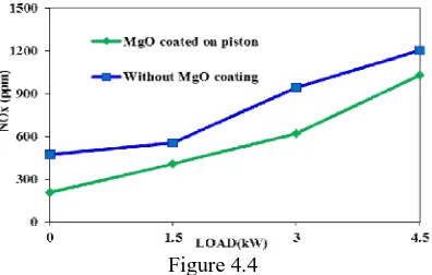
Figure 4.4
The variation of NOx emission for the both cases is shown in Figure 4.2 d. In this case, it is observed that, the reduction
level at lower (minimum) load is 55% and at higher load (4.5 kW) is only 14%. However the overall conversion efficiency has been observed as decreased for all loads. Further, the NOx emission level has gradually increased from
this study, it is clear that MgO coating on piston has facilitated this enhancement of emission control of all pollutants of this study to a greater extent.
Table 4
Pollutants Maximum Reduction in
Percent @ optimum load
NOX 62.59
CO 26.98
HC 51.65
CO2 18.77
Results obtained from the experiments shows that the Magnesium Oxide coated Catalytic filter effectively controls the emission of NOX and HC when the engine runs at the optimum load of 4.5 kW also the converter efficiency is more at
this optimum load.
V. CONCLUSIONS
Following are the conclusions based on experimental results.
The use of coating Magnesium Oxide over the pistons reduces the emission of
NOx by 62.59 percent. CO2 by 18.77 percent. CO by 26.98 percent.
HC by 51.65 percent.
From the conclusions it is found that the Magnesium Oxide was best catalyst to control the emission from the engines. When this catalyst coating over the piston is used, it may yield better results in reducing the NOx, HC and CO.
REFERENCES
[1] Bernard E. Enga, Miles F Buchman (1982), “Catalytic Control of Petrol Particulate”, SAE 820104. Pp.725-731 [2] Charles M Urban (1983), “Petrol Car Particulate Control Methods “SAE 830084 pp.1.278-1.287.
[3] Engler B H, Garr G T, Lox E S and Jung M G, “New Automotive Catalyst Development To Meet Future Emission Standards”, SAE 912600, 1991.
[4] Ganesan V, “Internal Combustion engines”, Tata Mcgraw-Hill, New Delhi, 2002.
[5] Heywood J B, ”International Combustion Engine Fundamentals”, pp. 148-152, McGraw-Hill Book Company, ISBN 0-07-100499-8,1998 [6] John S Howitt and Max R Montierth (1981), “Catalytic converter “SAE 810114.PP. 493-501
[7] “National Ambient Air Quality Standards” Central Pollution Control Board(CPCB), 11 April 1994
[8] Otto A Ludecke and David L Dimick (1983), “Petrol Exhaust Particulate Control System Development”, SAE 830085 pp.1.288 [9] “Stage II Emission Legislation Finalised”, Auto-Catalyst News of Johnson Matthey-U.K., Issue No.13, July 1994
[10] Steve C Brett, Derek Eade, Ron G Hurley, David Gregory, Ford Motor Co., Ltd., and Neil R Collind, Darrel Morris, and Ian T Collingwood, Johnson Matthey Plc. “Evaluation Of Catalyst Hydrocarbon Emissions Reduction”, SAE Paper 981417.
[11] Stroom P D, Merry R P, and Gulati S T, “Systems approach to Packaging Design for Catalytic Converters”, SAE Paper No 900500,Feb 1990. [12] “Swiatek George, Rudnicki Roman, Gettel Lorne and Unger Tom, Catalytic Exhaust Emission Control of Small I.C. Engines”, SAE 891799,
1989.
[13] Asaulyak, YV, Rozhdestvenskii & Gavrilov, KV 2002, ‘Elastohydrodynamic Lubrication (EHL) of Piston Rings in the Internal Combustion Engine’, Procedia Engineering, vol. 150, pp. 536 – 540.
[14] Beg, R, Bose, P, Ghosh, B, Banerjee, T & Ghosh, A 1997, ‘Experimental Investigation on Some Performance Parameters of a Diesel Engine Using Ceramic Coating on the Top of the Piston’, SAE Technical Paper, 970207.