International Journal of Advanced Research in Computer Science
RESEARCH PAPER
Available Online at www.ijarcs.info
© 2010, IJARCS All Rights Reserve 41
Towards Formalizing Multi-Agent Systems Functional Requirements In Maude
Fathi Hamidane*
Department of Computer Science Cheikh Larbi Tbessi University
Tébessa-Algeria [email protected]
Farid Mokhati
Department of Computer Science Larbi Ben M’hidi University
Oum El Bouaghi-Algeria [email protected]
Habiba Belleili-Souici
Department of Computer Science Badji-Mokhtar University
Annaba-Algeria [email protected]
Abstract: In this paper we present a systematic approach allowing the translation of Multi-Agents Systems’ functional requirements described by extended UML (Unified Modeling Language) use case diagrams and, AUML (Agent UML) sequence diagrams into a formal specification writ-ten in Maude language. Our approach proposes firstly, exwrit-tending UML use case by using UML stereotypes for taking into account MAS’ speci-ficities. Secondly, we associate to each use case, one or more AUML sequence diagrams realizing the different possible scenarios relative to such a use case. Once elaborated, the different diagrams undergo a validation to assure inter-and intra model coherence. The formal and object oriented language Maude, base on rewriting logic, supports formal specification and programming of concurrent systems. The main motivations of this work are: (1) formalizing the functional requirements of MAS by using Maude language, and (2) integrating the validation of the coher-ence models, since the requirements elicitation phase, in a MAS development process.
Keywords: Functional requirements; Formal specification; Use case diagram; Agent UML; Rewriting logic; Maude
I. INTRODUCTION
Currently, Agent Oriented Software Engineering (AOSE) is a very active research domain. In this last decade several methodologies for developing MAS (GAIA[20], Tropos[2], Prometheus[17], DACS[3], etc) have been emerged in the literature in order to facilitate the development of MAS ap-plications. These methodologies certainly brought much important answers to MAS’ development process. However, the methodological aspect is not mastered yet. Indeed, none of these methodologies take into account the formalization of the functional requirements for the future system. The quality of model analysis has an extreme importance for the remain-der of the development process phases. Their formal specifi-cation and validation allow avoiding many problems that may affect the development quality as well as its cost [6].
In this context, use case diagrams play an important role for describing the functional requirements of object-oriented systems [14]. However, they must be extended by associating some enrichment based on UML stereotypes for taking into account MAS’ specificities. Each use case defines basic scenarios which may be described using one or more AUML sequence diagrams.
This work presents a systematic approach supporting the translation of functional requirements of MAS represented by extending UML use case diagrams and AUML sequence diagrams into a formal specification writing in Maude lan-guage. This last is multi-paradigms language which com-bines the functional programming and object-oriented pro-gramming. Furthermore, Maude is very powerful in terms of specification, validation and verification of concurrent sys-tems, making it a good candidate for specification and vali-dation of MAS. Our approach is structured in three principal steps.
In the first step, we use on the one hand, an extended UML use case diagram that represents the MAS’ functional requirements, and on the other hand, a set of AUML se-quence diagrams for realizing different scenarios of each use case. In the second step, we proceed to a validation process of the previously quoted diagrams to insure inter-and intra model coherence. The third step is devoted to generating a Maude specification from the cited diagrams. The main mo-tivations of this work are: (1) formalizing the functional requirements of multi-agents system by using Maude, and (2) integrating the formal validation of the coherence of the models, since the requirements elicitation phase, in a MAS development process.
The remainder of this paper is organized as follows. In section 2, we present a general overview of similar works. The diagrams used in our approach are presented in section 3. In section 4 we give a brief overview of rewriting logic and Maude language. The proposed approach and the transla-tion process are presented in Sectransla-tions 5 and 6 respectively. Section 7 illustrates the translation process using a concrete case study. Finally, we give a conclusion and future work directions in section 8.
II. RELATED WORKS
In the last years, several multi-agent systems develop-ment methodologies have emerged in the literature. We pre-sent briefly in this section three use case-based methodolo-gies for describing multi-agent systems’ functional require-ments.
© 2010, IJARCS All Rights Reserve 42 set of roles. The main advantage of MaSE is its ability to
follow change during the MAS developing process.
L. Padgham and M. Winikoff proposed in [17] the Pro-metheus methodology, which is agent based. This methodol-ogy employs UML use case diagrams for providing a global overview for the interconnection between actions, percep-tions and functionalities. One of the principal advantages of this methodology is its provision of “start-to-end” support and its application in large domain [18].
The MAS-CommonKADS (Multi-Agent System Knowl-edge Analysis and Development) [9] methodology incorpo-rates some techniques from OO methodologies such as OMT [19] and OOSE [10] and also protocol engineering method-ologies. It also uses use cases to understand the informal requirements. Among the advantages of this methodology is the reusability of models and the fact that it covers the soft-ware development life cycle of a multi-agent system.
Although these methodologies brought much important answers in the development process and in particular for describing MAS’ requirements, they methodologies offer only informal or semi-formal descriptions for representing MAS’ functional requirements. Our approach offers a joint representation of the functional requirements while profiting from the advantages of the semi-formal and the formal ap-proaches. Furthermore, the proposed formal approach, allows reducing confusion and misunderstanding risks between developers and users.
III. USED DIAGRAM
A. Use Case Diagram
Often, users are not computer scientists. Thus they need a way to express their requirements. This is precisely the role of use case diagrams. These later are means for specifying required usages of a system. Typically, they are used to cap-ture the requirements of a system, that is, what a system is supposed to do [16]. A use case diagram is represented by use cases, actors and the relationship between them.
B. AUML Sequence Diagram
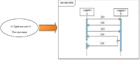
[image:2.595.317.570.610.755.2]The AUML sequence diagram describes interactions be-tween agents. It extends UML sequence diagram by intro-ducing some extensions supporting the sending of concurrent messages. To describe the threads interaction, AUML intro-duced three ways to express the multiple threads (see figure 1). Figure 1(a) indicates that all communicative acts CA-i (CA-1,…, CA-n) are sent concurrently (AND operator). Figure 1(b) includes a decision box which allows the com-municative acts to be sent (zero or several) (OR operator). Figure 1(c) indicates that one and only one CA must be sent (XOR operator) [1].
Figure 1. Recommended extension supporting the threads concurrent of
interaction
IV. REWRITING LOGIC AND MAUDE
A. Rewriting logic
Rewriting logic was introduced by Meseguer [12]. Based on a sound and complete semantics, this logic allows the description of concurrent systems [13, 11, 8, 5]. This logic unifies all the formal models that express concurrency [12]. It allows describing the concurrent systems which have states and which evolve in term of transitions. This logic is repre-sented by a rewriting theory T= (Σ, E, L, R):
• The static structure of the system is described by the signature (Σ, E) which represents the states of a sys-tem. Where Σ represents a pair of sorts and func-tions, E represents a set of equations.
• The dynamic structure is described by rewriting rules that take the following form: R : [t] → [t’] if C, which indicates that, according to rule R, term t be-comes or is transformed into t’ if a certain condition C is verified. This rule has a conditional form. There also exist unconditional rules where the conditional term C is not present.
B. Maude
Maude is a formal language for declarative programming and a formal specification tools based on rewriting logic [12, 4, 5, 11]. It can model systems and actions. Three types of modules are defined in Maude. Functional modules allow defining data types and their functions. System modules allow defining the dynamic behavior of a system. This type of module augments the functional modules by introducing rewriting rules. Finally, object-oriented modules, which can be reduced to system modules, offer a more appropriate syntax to describe the basic entities of the object paradigm. Maude environment has an incorporated model checker. However, model checking is out of the scope of this paper, but will be addressed in a future work. The choice of Maude is motivated by (i) Maude supports the object-oriented para-digm, which is not supported by the majority of the methods and formal tools, (ii) its capacity to model the concurrent systems and (iii) its formal specifications are executable, allowing users to validate their simulation systems. Further-more, Maude has some advantage like: simplicity, expres-siveness and performance.
V. PROPOSED APPROACH
In this section, we present our approach that allows ob-taining a Maude formal specification from extended UML use case diagram and AUML sequence diagrams.
Collective Behaviors Functional Requirements
Figure 2. Methodology of the approach.
Extended Use case Diagram AUML Sequence Diagrams
Validation and Translation
[image:2.595.67.274.622.704.2]© 2010, IJARCS All Rights Reserve 43
A. Extending UML Use Case Diagram
This part presents some extensions we consider useful for UML use case diagram in order to take into account MAS’ specificities. First extension proposed is notations used to describe agents involved in the system. These notations con-sider an agent as internal actor in the system, i.e. we can associate a set of internal actor playing agents’ role to UML use case diagram. Thus, we have two types of actors within the same extending UML use case diagram, namely the in-ternal actors (agents which constitute the system) and exter-nal actors (the actors who represent all exterexter-nal entities to the system). The notation associated to internal actors, is similar to the notation used to represent external actors, except that the head should be square (figure 3 (a)). External actor nota-tion (figure 3 (b)) is the same used in UML use case dia-grams. To represent use case for agents we extend the nota-tion use case in UML use case diagrams by adding the stereotype “Agent use case” (figure 3 (c)).
[image:3.595.332.559.56.179.2]<<Agent use case>> Use case name
Figure 3. (a) Internal actor, (b) External actor, (c) Agent use case.
B. Translation into AUML Seaquence Diagram
Use cases describe the various functionalities of future software product at a high level of abstraction. The realiza-tion of these funcrealiza-tionalities is accomplished using the inter-action diagrams to capture different possible scenarios. UML sequence diagrams don’t take into account agents’ specifici-ties; we opt for AUML sequence diagrams to realize differ-ent use cases that describe the functional requiremdiffer-ents of agents’ system. The passage of use case diagrams to AUML sequence diagrams is performed according to the following cases:
The first case corresponds to the one where each use case is realized by one AUML sequence diagram. Such use case doesn’t join another use case. Figure 4 shows how is made the translation.
Figure 4. Realization of use case via AUML sequence diagram.
[image:3.595.317.559.222.394.2]The second case of the translation, is when two or more use cases are joined with an include relationship. This last is stereotyped «include». The semantic aspect of the inclusion relationship means the inclusion behavior of a use case into another. So we can gather two use cases that are connected with the include relationship in one AUML sequence dia-gram, using the reference operator ref (a reference can be seen as a pointer or shortcut to another existing AUML se-quence diagram) in AUML sese-quence diagram (figure 5).
Figure 5. Describing the include relationship with AUML sequence
[image:3.595.44.277.260.332.2]diagram. The AUML sequence diagram 1 and 2 represent the scenario ofthe use case i and j respectively.
Figure 6. Describing the extending relationship with AUML sequence
diagram. The AUML sequence diagram 1 and 2 represent the scenario of the use case i and j respectively.
The third case of translation corresponds to the one where two or more use cases are connected with an extend relation-ship. This last is stereotyped «extend». In extend relationship we have extending and extended use cases. The semantic aspect of this relationship specifies how and when the behav-ior defining the extending use case can be inserted into the behavior defining in the extended use case. The extension can arise at a precise point of an extended use case. This point is called the extension point. Extension is often condi-tional. So the execution of the scenario represented by the extending use case depends on the satisfaction of the condi-tion represented in the extension point. Thus the translacondi-tion of this relationship to AUML sequence diagram is done by using the alternative operator alt (The alternative operator, or alt, is a conditional operator having several operands equiva-lent to an execution with multiple choices). Figure 5 presents this translation.
The final case is the generalization relationship that has the same concept as the inheritance. In this relationship, the use case that has more information is a specialization of the generalized use case. The passage from generalization rela-tionship to AUML sequence diagram is showed in figure 7.
(a) (b) (c)
[image:3.595.50.288.527.629.2]© 2010, IJARCS All Rights Reserve 44
Figure 7. Describing the generalization relationship with AUML sequence
diagram. The AUML sequence diagram 1 and 2 represent the scenario of the use case j and i respectively.
VI. TRANSLATION PROCESS
[image:4.595.27.280.312.568.2]A. Generated Maude modules
Figure 8. The formal framework’s architecture
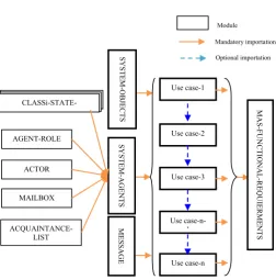
During the translation process, we have developed a for-mal framework. Several modules are generated. Figure 8 illustrates those modules. Our framework is composed of five functional modules and the rest are object-oriented mod-ules (modmod-ules in bold). For reasons of space limitation, we present only the most essential modules in this paper.
An agent is specified by its state values, its roles, its mail-box and its acquaintances list. These characteristics are de-fined respectively in the CLASS-STATE-VALUES, AGENT-ROLE, MAILBOX and ACQUAINTANCE-LIST modules. State values of an agent are specified in a func-tional module whose name is the concatenation of the agent class name and the string value State- Values.
We define an object oriented module MESSAGE (figure 9) for defining all the exchanged messages between entities. A message must contain the names of the sender, recipient
and its content (line [1]). This module also describes the form of the internal event processed by an agent (line [2]).
VII.
VIII.
omod MESSAGE is sort content .
msg Message : Oid Oid content -> Msg . ***[1] msg Event : Oid content -> Msg . ***[2] endom
Figure 9. The object oriented module MESSAGE.
The module SYSTEM-AGENTS (figure 10) is an ori-ented object module which defines the base structure of agents class involved in the system. This class has as attrib-utes, PlayRole, State, MBox and AcqList to contain in this order, the role played by the agent, its current state, his mail-box and a list of its acquaintances. To describe the objects manipulated by system’s agents, we propose the object ori-ented module SYSTEM-OBJECTS in which we declare the different object classes.
Figure 10. The object oriented module SYSTEM-AGENTS.
To each use case is associated an oriented object module Use-Casei bearing the same name of the corresponding use case. In each module Use-Casei are defined the rewriting rules describing the different interaction scenarios between the agents defined in the different AUML sequence dia-grams, instances of the use case. A module describing a use case can import (optional importation) another describing a use case which is linked to it. Once generated, the modules Use-Casei are imported in the object oriented module MAS-FUNCTIONAL-REQUIREMENTS (Figure 11) representing the main module. This module describes, in fact, the sys-tem’s dynamic behavior from the user’s point of view.
omod SYSTEM-AGENTS is including ACQUAINTANCE-LIST . including AGENTS-STATES . including AGENT-ROLE . including MAILBOX . sort AgentState .
class Agent | PlayRole : AgentRole,State:AgentState, MBox: MailBox, AcqList : AcquaintanceList. …
endom
omod MAS-FUNCTIONAL-REQUIREMENTS is including Use-Case1 .
including Use-Case2 . …
including Use-Casem . endom
Mandatory importation
Optional importation
Use case-n Use
case-n-1 Use case-3 Use case-2 Use case-1
AGENT-ROLE
CLASSi-STATE- ACQUAINTANCE-LIST MAILBOX
ACTOR
SYST
E
M
-AGE
NT
S
Module
SY
STEM-O
BJ
ECTS
MESSAGE
MAS-F
U
NCT
ION
A
L
-RE
Q
UIE
R
ME
NT
S
Figure 11. The main module MAS-FUNCTIONAL-REQUIREMENTS.
B. Description of the Relationship between Use Cases in Maude
1) Include Relationship Stereotyped <<include>>: As
© 2010, IJARCS All Rights Reserve 45 specification of the include relationship between two use
cases i and j (see figure 5).
Figure 12. Specification of include relationship.
2) Extend Relationship Stereotyped <<extends>>: As
shown in figure 6, an extended use case needs to reuse an extending use case in order to accomplish some functionalities. The execution of the extending use case depends on the satisfaction of the condition of the extension point. For describing extend relationship in Maude, the module that describes the EXTENDED USE-CASE must import the one that describes the EXTENDING USE-CASE. We use a conditional rewriting rule (line [1] of figure 14), where its condition represents the one of the extension point.
The configuration Configurationk+1 generated by the
rewriting rule describing the extension point (line [1] of figure 14) must be able to trigger the first rewriting rule in the module describing the extending use case (line [1] of figure 13), so the intersection between Configurationk+1 (line [1] of figure 14) and Configuration1 (line[1] of figure 13), must be different to the empty set (Configuratinok+1∩
Configuration1≠ Ø).
Figure 13. Formal specification of the extending use case-j in Maude.
Figure 14. Formal specification of an extended use case-i in Maude.
3) Generalization Relationship: This type of
[image:5.595.333.543.611.750.2]relationship will be translated also into Maude by importing modules. We have two sorts of use case linked by this generalization relationship, one is special use case and the other is general use case. The translation into Maude is done as follows: the module that describes the special use case (figure 16) must import the one that describes the general use case (figure 15) by the creation of some subclasses in the special module using the keyword subclass (line [1] of figure 16). Such subclasses inherit properties of the classes defined in the general module. Instances of subclasses can
reuse the rewriting rules defined in the imported module (the general module).
Figure 15. Formal specification of a general use case-i in Maude.
Figure 16. Formal specification of a special use case-j in Maude.
Note that the three interaction modes defined in AUML sequence diagram are all supported by Maude (for more information see [15]).
VII. CASE STUDY: THE BANK SYSTEM
In this section we apply our approach on a concrete ex-ample. The bank system represents a good example for vali-dating our approach because it contains all identified rela-tionships between use cases and it is clear and easy to under-stand.
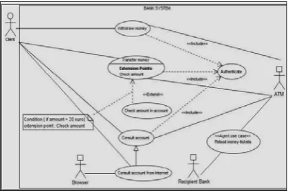
The functional requirements of the bank system are de-scribed by the extended use case diagram of figure 17.
This diagram is extended by using internal actors repre-senting system’s agents and all interactions between agents will be represented by use cases stereotyped <<Agent use case>>. We identify three internal actors (agents) playing the following roles: ATM (Automatic Teller Machine), Recipi-ent Bank and Browser. CliRecipi-ent is an external actor which interacts with the bank system. Each agent use case describes a functionality provided by the system. For example, the agent use case Reload money-tickets represent a functional-ity accomplished via interaction between the ATM agent and Recipient-Bank agent in order to reload money tickets.
omod INCLUDING-USE-CASE-i is
including INCLUDED-USE-CASE-j . *** importing the module
describing the behaviour of the use case j.
rl [1] : Configuration1 => Configuration2 . …
rl [n] : Configurationn-1 => Configurationn . endom
omod EXTENDING-USE-CASE-j is …
rl[1] : Configuration1 => Configuration2 . ***[1] …
rl[m] : Configurationm => Configurationm+1 . endom
omod EXTENDED-USE-CASE-i is including EXTENDING-USE-CASE-j . …
crl[k] : Configurationk => Configurationk+1 ***[1] if (condition in extension point is true) .
***Execution of EXTENDING-USE-CASE-j behaviour *** crl[l] : ConfigurationL => ConfigurationL+1 .
… endom
omod GENERAL-USE-CASE-i is class CG1 | Att11:Type11,…, Att1n:Type1n . …
class CGm | Attm1:Typem1,…, Attmn:Typemn .
rl[1] : Configuration1 => Configuration2 . …
rl[m] : Configurationm-1 => Configurationm . endom
omod SPECIAL-USE-CASE-j is
including GENERAL-USE-CASE-i . *** importing the GENERAL- USE-CASE-i . subclass CSk < CGl . *** [1]
…
Class CSk | Attk1:Typek1, …, Attkn:Typekn .
rl[1] : Configuration1 => Configuration2 . …
rl[n] : Configurationn-1 => Configurationn . endom
© 2010, IJARCS All Rights Reserve 46
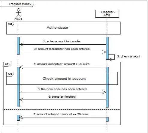
Figure 18. AUML sequence diagram of the use case TransferMoney.
After representing the functional requirements using an extended use case diagram, the next step is devoted to realiz-ing the different use cases usrealiz-ing the AUML sequence dia-grams. For clarity and simplicity, we only present the use case TransferMoney which has two relationships with other use cases. The first relationship is via the include relationship with the Authenticate use case and the second one is via the
extend relationship with the CheckAmountInAccount use
case. Figure 18 illustrate AUML sequence diagram realizing
TransferMoney agent use cases.
A. Application of the Translation Process
By applying the proposed translation process we obtain the modules described in our framework as follow: ATM-STATE-VALUES (figure 19), RECIPIENT-BANK-STATE-VALUES and BROWSER-STATE-RECIPIENT-BANK-STATE-VALUES. These mod-ules describe respectively the states of different agents in the system: ATM, RECIPIENT-BANK, and BROWSER.
Figure 19. The functional module ATM-STATE-VALUES.
The module AGENT-ROLE (figure 20) allows defining the roles played by system’s agents. Here are three roles defined: ATM, RECIPIENT-BANK and BROWSER.
Figure 20. Module AGENT-ROLE.
All external actors are defined in module named ACTOR (figure 21). In our example there is one external actor called Client.
Figure 21. The functional module ACTOR.
The module MESSAGE (figure 22) describes all mes-sages exchanged in the banking system. Line [1] presents the content of messages exchanged between different entities of the system.
Figure 22. The object module MESSAGE.
The next module is an object module named BANK-AGENTS (figure 23). This module imports the modules:
ACQUAINTANCE-LIST, ATM-STATE-VALUES,
RECIPIENT-BANK-STATE-VALUES,
BROWSER-STATE-VALUES, AGENT-ROLE, and MAILBOX. In addition, it
contains the definition of the class Agent describing the base class of agents (line [1]), and the definition of the class We-bAgent (line[2]), a subclass of the class Agent, which
spe-cializes by the WebSite attribute defining the address of the
Bank Web site. Line [3] represents the definition for different system’s agents: ATM, Recipient and Browser.
BANK-OBJECTS (figure 24) is an object module that contains the definition of the object class Account (line [1])
that describes a bank account and has as attributes: bal and amount representing respectively the current amount and amount to withdraw. In this case study we need two bank accounts for that; we define in this module Acc and Acc1
(line [2]) which are identifiers of two objects of the Account
class.
fmod ATM-STATE-VALUES is sort AtmStateValue .
ops StartA WorkA BreakDownA WaitA EndOperationA : -> AtmStateValue .
endfm
fmod AGENT-ROLE is sort AgentRole .
ops ATM RECIPIENTBANK BROWSER : -> AgentRole . endfm
omod MESSAGE is including ACTOR . including STRING . sort content . subsorts Actor String < Oid . msg Message : Oid Oid content -> Msg . msg Event : Oid content -> Msg .
**************user part****************** ops insercard entercode … -> content . ***[1] endom
omod BANK-AGENTS is
including ACQUAINTANCE-LIST . including ATM-STATE-VALUES .
including RECIPIENT-BANK-STATE-VALUES . including BROWSER-STATE-VALUES . including AGENT-ROLE .
including MAILBOX . sort AgentState .
subsort AtmStateValue < AgentState . subsort RecipientStateValue < AgentState . subsort BrowserStateValue < AgentState .
class Agent|PlayRole : AgentRole, State: AgentState,
MBox : MailBox, AcqList : AcquaintanceList. ***[1] class WebAgent | WebSite : WebAdress . ***[2] subclass WebAgent < Agent .
ops Atm Recipient Browser : -> Oid . ***[3] endom
fmod ACTOR is sort Actor . op Client : -> Actor . endfm
[image:6.595.36.283.66.288.2]© 2010, IJARCS All Rights Reserve 47
Figure 24. Module BANK-OBJECT.
The module TRANSFER-MONEY (figure 25) imports two modules AUTHENTICATION and CHECK-AMOUNT-IN-ACCOUNT. This module implements a trans-fer of money between two bank accounts (Acc and Acc1) (line [4]). To accomplish this functionality, it is needed to execute, on the one hand, the authenticate process via impor-tation of the AUTHENTICATE module, and on the other hand, the rewriting rule in this later which generates the message Message(Atm, Client, acceptedcode). This message
allows triggering the rewriting rule [IncludingLink] (line[1]
of figure 25) for starting the transfer-money process. Such functionality is extended by including the module
CHECK-AMOUNT-IN-ACCOUNT when the rewriting rule
[amoun-taccepted] (line[2] of figure 25) is executed. The execution
of this rule means that the condition of the extension point (A > 20; A is the amount) is satisfied. It generates the message
Message(Atm, Client, amountaccepted) used for triggering
the first rewriting rule of the module CHECK-AMOUNT-IN-ACCOUNT. If the amount to be transferred is available, another rewriting rule in this same module will be executed to generate the message Message(Atm, Client,
enterthenew-code) which will be used for triggering the rewriting rule
[ReferenceLink] (line[3] of figure 25) that allows the
execu-tion of the rewriting rule [transferfinished] (line[4] of figure
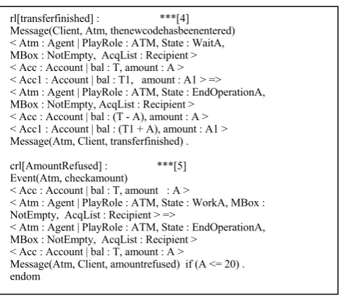
25) to indicate that the transaction transfer-money has been successfully achieved between the bank accounts Acc and Acc1.
Figure 25. Module TRANSFER-MONEY.
The object-oriented module
MAS-FUNCTIONAL-REQUIREMENTS (Figure 25) constitutes the principal
mod-ule generated by our approach. It imports the modmod-ules:
CONSULT-ACCOUNT, WITHDRAW-MONEY,
TRANSFER-MONEY, CONSULT-ACCOUNT-FROM-INTERNET and
RELOAD-MONEY-TICKETS.
Figure 26. Module MAS-FUNCTIONAL-REQUIREMENTS.
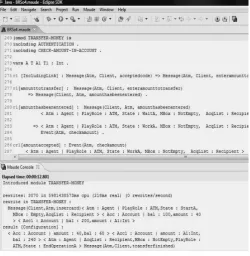
B. Validation of the Generated Description
Figure 27 illustrates a part of the code we developed. It visualizes, on the one hand, the module TRANSFER-MONEY and, on the other hand, the unlimited rewriting of an initial configuration. This later shows an agent playing the role ATM, in its initial state StartA with an empty mailbox
and has as acquaintance the Recipient agent. Furthermore, this configuration contains two objects Acc and Acc1 de-scribing two bank accounts whose contents are respectively 100 and 200 Euros. The banking transaction described by this module, is used to transfer the sum of 40 euros from Acc to Acc1. First of all, this operation requires the insertion of the bank card, which is described in this configuration by the message Message(Client, Atm, InserCard). The result of the
unlimited rewriting shows that the balance of the bank ac-count Acc is decreased by 40 euros (it became 60 euros),
while the balance of the bank account Acc1 is increased by
the same amount, so it becomes 240 Euros.
omod BANK-OBJECTS is
class Account | bal : Int, amount : Int . ***[1] ops Acc Acc1 : -> Oid . ***[2] endom
omod TRANSFER-MONEY is
including AUTHENTICATE . ***The included use case
including CHECK-AMOUNT-IN-ACCOUNT. ***The extending use case
…
[IncludingLink] : ***[1] Message(Atm, Client, acceptedcode ) =>
Message(Atm, Client, enteramounttotransfer).
rl[amounttotransfer] :
Message(Atm, Client, enteramounttotransfer) => Message(Client, Atm, amounthasbeenentered).
rl[amounthasbeenentered] :
Message(Client, Atm, amounthasbeenentered) < Atm : Agent|PlayRole: ATM,State : WaitA, MBox : NotEmpty, AcqList : Recipient > =>
< Atm : Agent | PlayRole : ATM, State : WorkA, MBox : NotEmpty, AcqList : Recipient > Event(Atm, checkamount) .
crl[amountaccepted] : ***[2] Event(Atm, checkamount)
< Acc : Account | bal : T, amount : A > < Atm : Agent | PlayRole : ATM, State : WorkA, MBox : NotEmpty, AcqList : Recipient > => < Atm : Agent | PlayRole : ATM, State : WaitA, MBox : NotEmpty, AcqList : Recipient > < Acc : Account | bal : T, amount : A >
Message(Atm, Client, amountaccepted) if (A > 20) .
***Part where the module CHECK-AMOUNT-IN-ACCOUNT must be executed if the extension point is verified***
rl[ReferenceLink] : ***[3] Message(Atm, Client, enterthenewcode) => Message(Client, Atm, thenewcodehasbeenentered) .
omod MAS-FUNCTIONAL-REQUIREMENTS is including CONSULT-ACCOUNT .
including WITHDRAW-MONEY . including TRANSFER-MONEY .
including CONSULT-ACCOUNT-FROM-INTERNET . including RELOAD-MONEY-TICKETS .
endom
rl[transferfinished] : ***[4] Message(Client, Atm, thenewcodehasbeenentered) < Atm : Agent | PlayRole : ATM, State : WaitA, MBox : NotEmpty, AcqList : Recipient > < Acc : Account | bal : T, amount : A >
< Acc1 : Account | bal : T1, amount : A1 > => < Atm : Agent | PlayRole : ATM, State : EndOperationA, MBox : NotEmpty, AcqList : Recipient >
< Acc : Account | bal : (T - A), amount : A > < Acc1 : Account | bal : (T1 + A), amount : A1 > Message(Atm, Client, transferfinished) .
crl[AmountRefused] : ***[5] Event(Atm, checkamount)
< Acc : Account | bal : T, amount : A >
< Atm : Agent | PlayRole : ATM, State : WorkA, MBox : NotEmpty, AcqList : Recipient > =>
< Atm : Agent | PlayRole : ATM, State : EndOperationA, MBox : NotEmpty, AcqList : Recipient >
< Acc : Account | bal : T, amount : A >
[image:7.595.319.561.91.303.2]© 2010, IJARCS All Rights Reserve 48
Figure 27. Validation via simulation of the generated description.
VIII. CONCLUSION AND FUTURE WORK
The formalization of functional requirements represents an important activity during development process of multi-agent systems. It produces a rigorous description and offers a solid basis for the verification and the validation activities. Several methodologies describing MAS’ functional require-ments using use case diagrams are proposed. However, they only offer informal or semi-formal descriptions. In this paper we proposed a generic approach that allows firstly, capturing MAS’ functional requirements using use case diagrams and AUML sequence diagrams, and secondly, translating the graphical description in a formal description Maude. This later characterizes by the power of description and integrates several tools of verification and validation. In this paper, we only applied the simulation as validation tool.
As future work we propose some suggestions for extend-ing our approach in order to take into account: (1) the struc-tural aspects of MAS, and (2) real time aspects of MAS.
IX. REFERENCES
[1] B. Bauer, J. P. Müller, J. Odell. “Agent UML: A
Formalism for Specifying Multiagent Software Systems,” International Journal on Software Engineering and Knowledge Engineering (IJSEKE), 2001, Vol. 11, No. 3, pp.1-24.
[2] P. Bresciani, P. Giorgini, F. Giunchiglia, J. Mylopolous,
and A. Perini, “Tropos: An agent-oriented software development methodology,” Autonomous Agents and Multi-Agent Systems, 8(3), 2004, pp203-236.
[3] S. Bussmann, N.R. Jennings, and M. Wooldridge,
“Multiagent Systems for Manufacturing Control: A Design Methodology,” in Series on Agent Technology, Springer-Verlag: Berlin, Germany, 2004.
[4] M. Clavel, F. Durán, S. Eker, P. Lincoln, N.
Martí-Oliet, J. Meseguer and J. F. Quesada, “Maude: Specification and Programming in Rewriting Logic,” Theoretic Computer Science, 2001.
[5] M. Clavel, F. Durán, S. Eker, P. Lincoln, N.
Martí-Oliet, J. Mesenguer and C. Talcott, “Maude Manual” (Version 2.1.1). April 2005.
[6] D.H. Dang, “Validation of System Behavior Utilizing
an Integrated Semantics of Use Case and Design Models,” in Claudia Pons, editor, Proceedings of the Doctoral Symposium at the ACM/IEEE 10th International Conference on Model-Driven Engineering Languages and Systems (MoDELS 2007). Nashville (TN), USA, CEUR, Vol-262, October 1st, 2007.
[7] S. A. DeLoach, M. Woodldridge, and C. H. Sparkman,
“Multiagent Systems Engineering,” The International Journal of Software Engineering and Knowledge Engineering, June 2001, 11(3), pp. 231-258.
[8] S. Eker, J. Meseguer and A. Sridharanarayanan, “The
Maude LTL Model Checker,” Elsevier Science B V, 2002.
[9] C.A. Iglesias, M. Garijo, J.C. Gonzalez and J.R.
Velasco, “Analysis and design of multiagent systems using MAS-CommonKADS,” Proceedings of the 4th International Workshop on Intelligent Agents IV, Agent Theories, Architectures, and Languages July 24-26, 1997, p.313-327,.
[10] I. Jacobson, M. Christerson, P. Jonsson, and G.
Overgaard, “Object-Oriented Software Engineering- A Use Case Driven Approach,” ACM Press, Addison Wesley, 1992.
[11] T. McCombs, “Maude 2.0 Primer,” Version 1.0.
Internal report, SRI International, 2003.
[12] J. Meseguer, “A Logical Theory of Concurrent Objects
and its Realization in the Maude Language,” G Agha, P Wegner and A Yonezawa, Editors, Research Directions in Object-Based Concurrency. MIT Press, pp. 314-390, 1992.
[13] J. Meseguer, “Software Specification and Verification in Rewriting Logic,” Computer Science Department, University of Illinois at Urbana-Champaign, 2003.
[14] F. Mokhati, and M. Badri, “Generating Maude
Specifications From UML Use Case Diagrams,” in Journal of Object Technology, vol. 8, no. 2, March-April 2009 pp. 119-136.
[15] F. Mokhati, B. Sahraoui, S. Bouzaher, M.T. Kimour,
“A Tool for Specifying and Validating Agents’ Interaction Protocols: From Agent UML to Maude,” in Journal of Object Technology, vol. 9, no. 3, May - June
2010, pp. http://www.jot.fm/issues/issue_2010_05/article2/
[16] Object Management Group “Unified Modeling
Language: Superstructure version 2.1.1,” February 2007.
[17] L. Padgham, and M. Winikoff, “Prometheus: A
methodology for developing intelligent agents,” in the Proceedings of the First International Joint Conference on Autonomous Agents and Multi-Agent Systems (AAMAS 2002), Bologna, Italy, July2002 pp15-19.
[18] L. Padgham, and M. Winikoff, “Prometheus: A
Pragmatic Methodology for Engineering Intelligent Agents,” in the proceedings of the workshop on Agent-oriented methodologies at OOPSLA ., Seattle USA November 4, 2002.
[19] J. Rumbaugh, M. Blaha, W. Premerlani, F. Eddy, and
W. Lorensen, “Object Oriented Modeling and Design,” Prentice-Hall, 1991.
[20] M. Wooldridge, N.R. Jennings, and D. Kinny, “The
[image:8.595.38.289.58.315.2]![Figure 1(c) indicates that one and only one CA must be sent (XOR operator) [1].](https://thumb-us.123doks.com/thumbv2/123dok_us/710771.1079367/2.595.317.570.610.755/figure-c-indicates-ca-sent-xor-operator.webp)