E N C O R E - A M o d e l of R e a c t o r Core C o n f i g u r a t i o n a n d L o a d s
Colin D Elcoate 1) and John FB Payne 2)1) Frazer-Nash Consultancy Limited, 1 Trinity Street, College Green, Bristol, BS 1 5TE, UK.
2) BNFL Magnox Generation, Magnox Electric plc, Berkeley Centre, Berkeley, Gloucestershire, GL13 9PB, UK. ABSTRACT
Magnox and Advanced Gas-Cooled Reactor (AGR) graphite cores are constructed from columns of radially keyed graphite bricks on a square lattice surrounded by a steel restraint cage. The bricks in the bottom layer of the core are spigotted to a steel diagrid below them. To enhance the understanding of the structural behaviour of the core a software code, ENCORE, has been developed to predict external brick forces and associated brick displacements for full-scale core models. ENCORE enables boundary conditions to be specified based on the effects of thermal expansion and contraction of the restraint cage relative to the diagrid, brick bow due to neutron irradiation and diagrid deflection. The model determines the equilibrium configuration of the core as that which minimises the total potential energy of the core.
ENCORE has been proven to be an efficient, accurate and robust tool for core configuration modelling. Run times are significantly less than for alternative finite element methods with solution times of the order several hours on a SUN Ultra2 400MHz workstation for a three-dimensional model comprising 60000 bricks. ENCORE provides Magnox with the capability to analyse full core configurations for the first time. In addition, by virtue of its fast execution time, it also provides the ideal tool to build a full understanding of core behaviour under normal operation, transient or fault conditions. INTRODUCTION
This paper presents a software development program, ENCORE, carried out by Frazer-Nash Consultancy Limited (FNC) for BNFL Magnox Generation (Magnox) on behalf of the Industry Management Committee (IMC). FNC have built a strong and productive working partnership with Magnox providing support in the form of structural analysis, fluid dynamics and heat transfer, design, testing and software development. This work is a success to this collaboration.
An integral part of any core safety assessment is the ability to accurately predict the displacements and associated loads acting on core components. Historically, Magnox have developed there own core configuration codes but have also used commercial codes (i.e. ABAQUS) to model layers of the core as a series of spring elements for example. Codes developed by Magnox prior to ENCORE were limited in their functionality (elastic deformation being ignored for example) and were only applicable to 2 dimensional (2D) vertical slices of the core. ABAQUS models were more refined with respect to functionality but long CPU times made the analysis of a full core (up to 60000 bricks) computationally prohibitive. To address these limitations and to enhance the understanding of core behaviour Magnox developed a 2D vertical slice version of ENCORE[I], [2] and [3]. The 2D vertical slice version incorporated a full functional capability accounting for elastic and gravitational potential energy (GPE) as well as accounting for the clearances associated with the core. To further enhance core understanding FNC developed a 2D horizontal layer version of ENCORE[4]. It was based on the 2D vertical slice model but with the added functionality to predict brick rotations and to deal with the complexities associated with the irregular core boundary. Finally, FNC developed a full 3 dimensional (3D) version of ENCORE[5] that incorporates the full functionality from both 2D models. The formulation presented in this paper is based on the full 3D version but is equally applicable to both 2D models.
MAGNOX AND AGR CORES
Magnox and AGR graphite cores are constructed from columns of graphite bricks on a square lattice. The bricks are connected in a way that restricts the relative movements between neighbours. In most Magnox and all AGR reactors the connections take the form of cruciform keys or spigots in the vertical direction and a radial keying system in the horizontal plane, Fig. 1. Radially-keyed Magnox cores are constructed from alternate columns of octagonally and squarely cross- sectioned bricks, Fig. 1. Adjacent bricks are linked together by loose radial keys, effectively constraining their relative position to within the clearance between a key and its keyway. The core is polygonally symmetric and is surrounded by a steel restraint cage which is connected to the bricks in the outside ring. The bricks in the bottom layer of the core are spigotted to a steel diagrid below them. During a transient, there could be relative movement between the restraint cage and the diagrid due to thermal expansion or contraction. Therefore the connections of the bricks to the restraint cage will displace the core away from the initial configuration and there is a need to predict the new core configuration. The cores are initially assembled with each brick vertical and standing squarely on the brick beneath it. This configuration is termed the initial configuration. If any bricks become bowed by neutron irradiation or the process described above takes place then this ideal configuration will not be possible.
SMiRT 16, Washington DC, August 2001 Paper # 1822
<>
[J
I I .... ° I I
.,
I K /
i,
L
E x(u)
y(v)
. . . . x(u)
' , s
Fig. 1 Diagrammatic Detail of a Typical Core Layer Showing the Orientation of Square and Octagonal Bricks
ASSUMPTIONS
The main assumptions that have been made in formulating ENCORE are listed below. • Friction between core components is neglected.
• Each brick is notionally square with a half width bw.
• The angles of brick rotation are small, and therefore first order approximations are made.
• The force deflection characteristics between components can be described using smooth functions. • The effect of brick bow is only to tilt brick end faces.
M E T H O D O L O G Y
The ENCORE methodology is based on calculating the equilibrium configuration of the core as the configuration that minimises the total potential energy. The total potential energy is the sum of the elastic and gravitational energies of the bricks and is a function of each brick's position (displacement and rotation) relative to its original position. A change in elastic energy can be the result of two mechanisms: elastic deformation from key to keyway contact or from corner to face contact, discussed below. The change in GPE is due to the change in heights of the centre of gravity (C of G) of the bricks as they are tilted from the initial position, also discussed below. The model described here neglects friction.
A result of neglecting friction is that the potential energy of the system for any configuration relative to a reference configuration can be found by path independent integration. As a result, if a configuration is such that it does not minimise the total potential energy of the core, there must exist another configuration with a lower potential energy nearby. The difference in potential energies between the two configurations must be the product of a force and its displacement in moving from one configuration to the other. Hence, when the total potential energy of the core is at a minimum then the net force acting must be zero.
To allow for keyway and brick to brick clearance, the elastic energies have to be non-linear functions of the displacement and rotation of one brick relative to its neighbour (the bricks may be thought of as being connected to their neighbours by non-linear 'springs'). Thus the total potential energy, whose minimum is to be found, is a non-linear function of the core configuration. ENCORE incorporates an efficient and robust Numerical Algorithms Group (NAG) library for minimisation of a non-linear function[6]. The storage requirements are proportional to the first power of the number of variables and the library is therefore suitable for large scale problems such as the whole core 3D model. The NAG library minimises an unconstrained nonlinear function using a pre-conditioned, limited memory quasi-Newton conjugate gradient method that solves the following problem:
minimise f ( £ ) , when - oo < £ < oo (1)
MODEL DESCRIPTION
The total potential energy of the core is a function of the position and orientation of the bricks comprising the core. For the purposes of this work the position and orientation of each brick is specified by two displacements (u and v) and one rotation (r). In addition, a diagonal displacement (uv) is used with respect to the octagonal brick corner keys. Brick tilt angles (~, and Or) are calculated in terms of the displacements u and v.
Keyway positions are defined as North (N), East (E), South (S) and West (W) for square and octagonal bricks. In addition, octagonal bricks have keyways located at the North East (NE), South East (SE), South West (SW) and North West (NW) positions. To account for each key to keyway contact once and only once, the 'springs' at the NW, N, N E and E positions of an octagonal brick are considered to belong to that brick. For a square brick, the 'springs' at its N and E positions are considered to belong to the brick. Similarly, 'springs' representing corner to face contacts at N and E faces are considered to belong to the brick. The total elastic energy is then the sum over all bricks, of the elastic energies of the 'springs' belonging to each brick. This is the most efficient method of handling each potential contact without duplication.
The core is designed in such a way that the movement of a key in and out of a keyway is only restricted by frictional force (which is ignored for the purposes of this model). Therefore, the displacement perpendicular to the North key and keyway, which governs the force can be written as:
uNuk = uuk - b w ' r u k (2)
and similarly for the other side key positions.
The scaled perpendicular displacement of the North East corner key position, as used in the code, is written as:
uv'NEuk = uij k - vii k - 2 b w . rij k (3) and similarly for the other corner key positions.
ELASTIC P O T E N T I A L E N E R G Y OF A LAYER OF BRICKS
In a given configuration of a layer, forces applied to a brick both at its keyways and on its faces can store elastic potential energy in the brick. The calculation of the elastic potential energy must allow for the clearances between the keys and the keyways and between bricks. These clearances allow a brick to move a small amount relative to its neighbour without exerting a force on its neighbour. Once the clearance is taken up, the force is proportional to further deflection, and the elastic energy is proportional to its square, like a linear 'spring'. In this context the 'spring' deflection, & is the difference in displacements of the appropriate adjacent brick positions. The lost motion is the small movement required to take up the clearances between key and keyways or bricks and is represented by ck and cb respectively.
Key to Keyway Contact
The modified potential elastic energy function for key to keyway contact, K, adopts a hyperbolic tangent function to model the clearance, and achieve a force deflection characteristic with a continuous second derivative and is written as:
(4)
The total elastic potential energy from key to keyway contact is the sum of the key energy over all active keys. An active key is one that 'belongs' to a brick within the core boundary, or is a boundary brick key that is associated with a brick within the core boundary. The total elastic potential energy from key to keyway contact can therefore be written as:
ni nj nk
£ £ £ (~ggij k 4;" OgEij k "1- ~gNWij k .-I-/],ggEij k )
i=1 j=l k=l
(5)
where y, r/, fl and ,,1, are either unity or zero depending on the position of the brick.
OK_lks(2~k__ _ 2cktanh~k
_ ~ksech 2 ~ k )
O~k 2 2ck 2ck (6)
Brick to Brick Contact
Consistently with the method adopted for the key to keyway contacts the clearance to contact characteristic is again represented by a continuous function. The modified potential elastic energy function for brick to brick contact, J, adopts an inverse tangent function to achieve an energy deflection characteristic with a continuous second derivative and is written as:
j = ks t~ + +
(m -2 +
~Z)tan-1 (m~ (7)2~ 2
where m is the parameter that defines the extent of the 'smooth' transition between zero and a quadratic energy/displacement characteristic (equivalent to a linear force/displacement characteristic).
The total elastic potential energy from brick to brick contact is the sum of the brick energy over all bricks with active North and East keys (and hence faces) and is written as:
i=1 j=l k=l
(8)
The derivative of the brick to brick elastic potential energy with respect to the spring deflection gives the forces acting on the bricks. The brick to brick potential energy gradient for a single contact is written as:
/ tan 'm"/
=_--k 6 1+ - + (9)
G R A V I T A T I O N A L P O T E N T I A L E N E R G Y
The GPE of the core is dependent on the height of the C of G of each brick. The height of the C of G is affected by brick tilt and brick bow, Figs. 2 and 3. The gravitational energy is taken to be zero when all bricks are straight (unbowed) and vertical. The change in the heights of the centres of gravity of the bricks determines the change in GPE as the bricks are tilted and bowed.
Effect of Brick Tilt
A tilt angle (¢), Fig. 2, is defined as the angle to the vertical of a straight line joining corresponding points on the top and bottom of the brick. The tilt angles are considered in terms of the u and v components of displacement, which are independent variables. The tilt angle in the x direction for brick ijk, to a first order approximation[ 1 ], is given by:
~ X ijk = lg ijk -- U ijk_l
ho k (10)
and similarly in the y direction.
Considering each tilt angle separately the change in the GPE of a part column of bricks (from ijk to nk) due to the tilt of the part column relative to the brick below in the x direction is linearised to give:
GXuk
= W~jk ]Oxuk I~uk
(11)and similarly for the change in GPE of a part column of bricks (from k to nk) due to the tilt of the part column relative to the brick below in the y direction.
Based on the assumptions that the two components of brick tilt contribute independently to the GPE, and that the bricks rock on a square base (ax/j k = ayij ~ = auk ), the change in the GPE of a part column of bricks (from k to nk) due to the tilt of the part column relative to the brick below in the x and y directions is given by:
x~" " ...
i i
----
E ck ijk-I
i#r I C
Z
~-x(u)
2
x(u)
..
"" ' ' " ' . . . , , . . . .
Ox+~M2 .~,','," ...
. . .
Fig. 2 Diagrammatic Representation of Tilted Bricks (in the x direction)
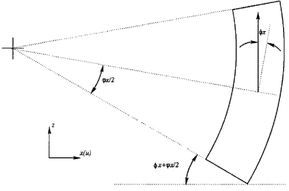
Fig. 3 Diagrammatic Representation of Bowed and Tilted Bricks (in the x direction)
Modification of the GPE to Include Brick Bow
Non-uniform fast neutron irradiation causes bricks to bow to approximately an arc of a circle, Fig. 3. The code makes the assumption that the effect of brick bow is only to tilt the end faces of the bricks. Consistently with the treatment of brick tilt it is assumed that two components of brick bow (in the x and y directions) contribute additionally to the GPE.
The effect of brick bow is similar to that of brick tilt in that it raises the C of G of all the bricks above it in the column. The bow angle in the x direction of brick
ijk (~pxuk),
Fig. 3, is defined as the angle between the top and bottom faces of the brick. The angle in the x direction of the bottom face of brickijk
is equal to half the bow angle ( ~pxuk / 2 ). Thus, theangle in the x direction between the top of brick
ijk-1
and the bottom of brickijk
(that is important when considering the change in the GPE) can be derived as:OXijk : ~)Xij k _ ~)Xij k-1 + (PXij k "1- (PXijk_ 1 ( 1 3 )
2
and similarly in the y direction.
The change in the GPE of a part column of bricks (from k to
nk)
due to brick tilt and brick bow in the x and y directions is the same as that given in Eq. (12) where 0xijk is given by Eq. (13) and similarly 0yuk.The Effect of Elasticity on the GPE of a Column of Bricks
The GPE term shown in Eq. (12) assumes that the bricks are perfectly rigid. However, it is necessary to include the effect of brick elasticity to avoid the discontinuity that occurs in the energy function at zero relative tilt angle. A function,
absish,
has been derived[ 1 ] to model the effect of elasticity. For combined tilt and bow in the x direction of brickijk
it can bedefined as:
absish(Oxuk)=(Oxuk)tanh(2!~idilkh)
I
(14)where
width
is the angle over which elastic behaviour is important and is set to 10 -3radians.
A similar expression can be derived for combined brick tilt and bow in the y direction:The function
absish
behaves similarly toabs
when10 .1
is much larger thanwidth,
but has a first derivative that isEffect of Diagrid Sag
Displacement of the diagrid supporting the core, under the weight of the core, is regarded as the tilting of a notional layer of bricks at the bottom of the core (layer zero). The lowest gravitational energy is with brick bottom face parallel to diagrid which is taken as zero GPE. To that extent the effect of vertical displacement is included in the formulation, however the resultant difference in the vertical distance from key to pivot corner of adjacent bricks is not included. The effect is therefore included in the theory described above for brick tilt. The angles of brick tilt for layer zero are boundary conditions prescribed by the user in the input file (as are the restraint cage displacements).
Total GPE of a Column of Bricks
The total change in GPE including the effects of brick tilt, brick bow, elasticity and diagrid sag can be written for brick
ijk
as:Gij k = Wukaij k (absish(Oxijk )+ (absish(Oyuk ))
(15)The total GPE for the whole core is the sum of the GPE of all the bricks and is given by:
ni nj nk
i=l j = l k=l
(16)
where Z is unity for a brick within the core boundary, and zero for a brick on or outside the core boundary. GPE Gradient
The gradients of the GPE with respect to the brick displacements u and v are required by the NAG function minimisation routine as part of the total potential energy gradient. The chain rule is used to obtain the gradients of the GPE with respect to u and v, from the derivatives with respect to 0x and 0y respectively. The derivative with respect to uijk of the total gravitational energy is given by:
I 1
1 Isignish(Oxijk+l)+ Wuk+2au~+2
signish(Oxuk+2)
(17)OuukOG Wu~aiflCsignish(Oxi#)_Wi#+lai#+lhi#+lhuk
hi#
hi#+1
and similarly for the derivative with respect to
vijk.
Note that terms with a subscript k+l or k+2 are omitted when the subscripts are larger thannk.
The function
signish[
1] is a continuous function and comes from the differentiation ofabsish
with respect to the angle between brick faces (0). For angle 0xsignish
is given by:si ni' h =tanhl20 -'- 120 sech2120
(18)and similarly for angle 0y. FORCES BETWEEN BRICKS
As well as the brick displacements and rotations for the equilibrium core configuration, the software also finds the forces acting on the bricks from key to keyway and brick to brick contacts. The forces are equal to the derivative of the energy with respect to the 'spring' deflections, Sk and ~b, and are given by Eqs. (6) and (9).
OBJECTIVE F U N C T I O N AND G R A D I E N T
The objective function, f(£" ) that is minimised by the NAG library is the total potential energy of the core. It comprises the total elastic potential energies of the core from key to keyway contacts and brick to brick contacts (Eqs. (5) and (8)) plus the GPE due to brick tilt, brick bow and diagrid sag (Eq. (16)) together with the potential energy associated with the user defined brick forces.
V E R I F I C A T I O N AND E X E C U T I O N
ENCORE has been verified via comparison with an extensive collection of analytic solutions to simplified core configuration problems[7]. The verification tests ranged from problems with uniform restrain cage displacements to small scale core simulations incorporating restraint cage displacement, brick bow, diagrid sag and user defined forces. The ENCORE solutions compared very well to the analytic solutions with typical errors in the calculation of brick displacements and forces of the order 0.1% and 0.001% respectively. In addition, the implementation was demonstrated as being efficient and robust with convergence to the potential energy minima guaranteed from a zero displacement initial condition.
Typical CPU times for the solution of 2D and 3D problems using the ENCORE codes on a SUN Ultra2 400MHz workstation are:
• 2D Vertical Slice (=700 bricks) - of the order 15 seconds. • 2D Horizontal Slice (=5000 bricks) - of the order 10 Minutes. • 3D Model (=60000 bricks) - of the order 3 hours.
The CPU time associated with the solution to any individual problem is dependent on the problem definition and the initial configuration of the core components. The times quoted above are believed to be an upper bound on typical solution times as the initial conditions for each are based on zero displacements, and the problems are derived such that the potential energy minimum is localised and hence inherently difficult to find.
S U M M A R Y AND C O N C L U S I O N S
A software code, ENCORE, has been developed by FNC and Magnox to predict the configuration of radially keyed core structures typical of those in Magnox and AGR reactors. The code methodology is based on calculating the equilibrium configuration of the core as the configuration that minimises the total potential energy of the core. ENCORE accounts for elastic and gravitational potential energy which is calculated as a non-linear function of each brick's position relative to its original position. The following physical features are considered:
• Elastic potential energy from key to keyway and brick to brick contact.
• The 'free' displacement associated with the key to keyway and brick to brick clearance. • Brick tilt and bow.
• Diagrid sag.
Extensive verification and testing demonstrates that not only does ENCORE agree very well with analytic solutions but has run times that are significantly less than for alternative methods. ENCORE provides Magnox with the capability to analyse full core configurations (up to 60000 bricks) for the first time. In addition, by virtue of its fast execution time, it also provides the ideal tool to build a full understanding of core behaviour under any number of normal operation, transient or fault scenarios.
N O M E N C L A T U R E
ax, ay bw cb ck E
~ )
G h i J
J
k K kc ks m N
= Brick rocking half width in the x and y directions (m) = Brick half width (m)
= Brick to brick clearance (m) = Half key to keyway clearance (m)
= Elastic potential energy (Nm) or East position of brick = Objective function
= Gravitational Potential Energy (Nm)
= Height of brick layer (m) = x axis index (row length)
= Brick to brick elastic potential energy (Nm)
= y axis index (row) = z axis index (layer)
= Key to keyway elastic potential energy (Nm)
= Brick comer 'spring' stiffness (N/m)
= K e y ' s p r i n g ' stiffness(N/m)
NE ni
nj
nk NW r S SE SW U UY Y W X Y Z Z 5 6bvj~ 2 )
5k
Cx, Cy
Y 0 qgx,Ox, Oy
= North East position of brick = Number of rows
= Number of bricks in r o w j = Number of layers
= North West position of brick
= Brick rotation about the z axis (radians)
= South position of brick = South East position of brick = South West position of brick = Displacement along the x axis (m) = Displacement along a diagonal (m) = Displacement along the y axis (m)
= Weight of bricks in a column above a given brick (N) or West position of brick = x axis (points East)
= y axis (points North) = z axis (vertical, positive up) = Active North West key indicator = Core brick indicator
= 'spring' deflection (m)
= Brick to brick 'spring' deflection (m) = Objective function gradient (N) = key to keyway 'spring' deflection (m)
= Angle of brick tilt in the x and y directions (about the y and x axes) (radians)
= Active North key / face indicator = Active East key / face indicator
= Brick bow angle in the x and y directions (about the y and x axes) (radians)
= Active North East key indicator
= Angle in the x and y directions (about the y and x axes) between brick faces (radians)
REFERENCES 1} . 0 0 11 1t
Kemp, E., Payne, J.F.B. and Rashid, T., "ENCORE 1: A Model of Brick Configuration and Keyway Loads for Magnox Reactor Cores", BNFL Magnox Generation Report,
M/TE/MAG/REP/0055/98, Issue 1, October 1998.
Payne, J.F.B., "Revision of the Gravitational Potential Energy Equation used in ENCORE", BNFL Magnox Generation Report, M/TE/MAG/REP/0040/99, Issue 1, December 1999.
Coleman, A. J., "The Reproducibility, Uniqueness and Accuracy of ENCORE Solutions for Core Configuration", BNFL Magnox Generation, M/TE/GEN/REP/0088/99, Issue 1, May 1999. Elcoate, C.D, "Extend ENCORE to 3D - Phase 1: User Guide for the ENCORE 2D Layer Program", Frazer-Nash Consultancy Limited Report, FNC 7281/2308RB, Issue 1, August 2000. Elcoate, C.D, "Extend ENCORE to 3D - Phase 2: User Guide for ENCORE3D", Frazer-Nash Consultancy Limited Report, FNC 7292/2348RB, Issue 1, October 2000.
"Section E04 Minimising or Maximising a Function" FORTRAN NAG Library Mark 4 Volume 3 D03 - E04J.