Estimation of Accuracy for Generation of
Realistic Surface Crack Patterns
Ankita Sharma1, Dr. Supreet Kaur
M.Tech Student, Dept. CSE, Punjabi University Regional Institute for Information Technology and Management,
Mohali, Punjab, India1
Assistant Professor, Dept. of CSE, Punjabi University Regional Institute for Information Technology and Management,
Mohali, Punjab, India2
ABSTRACT: One of the natural phenomena with the passage of time is degradation and deterioration of the various objects. Degrading is either physical or chemical disintegration or decomposition.
Computer graphics is a challenging field in itself. There are so many phenomena to be rendered in computer graphics such as object deformation, aging, object’s chemical decomposition or degradation etc. One such phenomena is realistic fracture and surface crack generation in computer graphics. It is one of the very complex phenomena to generate as there are many complexities involved together in the cracks and fractures’ generation.
Though great attempts have been done in this field to generate realistic crack patterns, still, a lots of work is still required to get a work of near perfection in this field. Out of so many techniques that are out there, to render the surface crack patterns but, current state-of-art is that, not a single generic solution to address all the complexities. Our work simply present a detail study about how much every statistical parameter of a crack, to be generated using example based model, is contributing in the realistic generation of a surface crack pattern.
KEYWORDS: Crack generation, degradation, rendering, surface crack patterns, realistic modelling, brittle cracks,
I. INTRODUCTION
There has been quite remarkable work done in the field of objects’ aging and weathering phenomena, due to environmental conditions, especially in the field of aging of the objects, over the time. Objects’ deterioration is of many forms such as chemical decomposition of the outer layer exposed to the environment, aging over the time, corrosion, peeling of outer layer of object’ surface and growth of the organic material over the surface of object etc.
Crack and fractures appearing on the surface of the object is also one of the aging phenomena with less amount of work done in this field as compared to the others’ when it comes to rendering cracks and fractures in the computer graphics in a realistic way. Though, out of all the work done in this field as mentioned in [13] broadly, we can classify the techniques used to generate the cracks patterns into three categories which are:
1) Physically based models: These methods follows the way of simulating the crack patterns by formulating the algebraic equations so as to formulate the model, on which cracks will be rendered, and then using numerical approximations to solve them. The simulation is effective but time consuming. Lots of calculation work is involved, so it gets complex while dealing with the large scenes.
Physically based models are further classified into following categories:
a) Mass-Spring model: In Mass-spring models, the object is treated as finite number of masses, pair-wise, joined with springs. If any crack has to be simulated it is done by breaking the string attached to two masses so as to show the crack appearance.
b) Finite element method: The partitioning of the object is done into the sets of disjoint elements, e.g. tetrahedrons, which are joined at discrete points. In the next step, the problem, formulated in the form of these points, is then converted into certain sets of algebraic equations which are then solved, so as to get desired results.
2) Procedural Models: Also called Geometry-based models. As the name suggests, these models are more concerned about the geometrical presentation of the cracked surface rather than physical accuracy. More intractability and freedom is provided to the users with little compromise on the accuracy of the crack pattern generated.
3) Example based models: Example based models map real world fractures. The behaviour of the fracture in the real world is copied. Using some interactive programs from computer graphics, the parameters of the cracks and fractures are extracted from the real world images and then the cracks are generated using those [14].
We chose to work with the Mathematical Tool called MATLAB™. Another software called Autodesk 3Ds Max is also used in our work.
II.RELATEDWORK
It started in 1976, when two researchers, Ed Catmull and Fred Parke, developed an animation of human face and hand, at the University of Utah. Then in 1979, Hakan Lawn, a Swedish researcher, applied for first patient in this field of
computer graphics field[1].
Trezopoulos, et al., 1988 in [2] presented a model which proposed inelastically deformable models for the use in computer graphics animation and they tractably simulated three canonical inelastic behaviours, which are viscoelasticity, fracture and plasticity. Viscous and plastic processes in the models, evolve a reference component, which depending on the yield and creep relationships that depends upon applied force and/or instantaneous deformation, describes the natural shape. The internal processes, that introduce local discontinuities as a function of the instantaneous deformations, measured through the model, results in simple fracture mechanics. The in elastically deformable models, are also applied to achieve good computer graphics effects.
Norton, et al., 1991 in [3] presented their methods of using physical simulation, so as to animate breaking objects. Breakage is obtained in a three-dimensional flexible model as the limit of elastic behaviour. Their article consisted three principal features of the model: a breakage model, a collision-detection/response scheme, and a geometric modelling method. They used networks of point masses, which connect through springs representing physical objects that can be bended or can be broken. The collision-detection algorithms, presented quite efficient and also appropriate simulations of the collisions between the various pieces interacting in a breakage. To model real objects, the technique is to build up composite structures from simple lattice models.
Gibson, et al., 1997 in [4] a survey is presented, of the work done in modelling deformable objects, in the computer graphics. The research includes a wide variety of approaches, used to model deforming. The organization of the diversity of research, in the paper, is by the technique used, over its application. The review paper presents some purely geometric approaches for the purpose of modelling deformable objects, and it also focuses on physically based approaches which are discussed in the latter category, some of which are mass-spring models, finite element models, low degree of freedom models and approximate continuum models. Special focus is on finite element models, offering the greatest accuracy, but is used limited in computer graphics.
Lin, et al., 1997 in [5] presented, a finite element method technique, used in the paper, step-by-step, three dimensional approach. The author simulated fatigue crack shapes, in round bars. They studied shape of growing crack by proposing two measures: Relative residual and the other one is Standard deviation.
Hirota, et al., 1998 in [6] in this paper, an approach has been described about generating realistic crack patterns, based on a physical model. The proposed model consists of nodes, representing the volume elements of the surface and springs denoting the physical connection between them. Fragmentation is denoted by cutting of springs.
O’brien et al., 1999 in [7] presented a little addition to existing techniques to simulate flexible objects to include models for crack initiation and propagation in three dimensional volumes. Stress tensor is analysed over a finite element model and the simulation determines the crack initiation and its propagation direction.
Smith et al., 2001 in [8] presented a method for the controllable and rapid simulation for the shattering of brittle objects. In the presented method, an object is taken as a set of point masses connected through distance-preserving linear constraints. These distance-preserving linear constraints gain significant advantages in speed of simulations, rather than stiff springs. Force exerted by these constraints gets computed using Lagrange multipliers and the calculated force determines, when, the object will break and velocity of newly created fragments.
determine, where cracks will appear on the surface. Cracks then propagate through a two dimensional grid and elasticity computes the paint stress around cracks.
Heieh et al., 2006 in [10] presented a method which consisted of a simple approach to render crack patterns and animation of crack propagation on three dimensional object surface. Generation of cracks are on 3D objects with some controllable parameters combined with variant visual effects such as bumping or carving.
S.Merillou et al., in 2008 [11] presents a survey of various aging and weathering phenomena in computer graphics. The paper includes various techniques which allows a representation of wide range of aging and weathering phenomena. It includes all the processes which involve simulation of cracks, growth of organic material over the surface, erosion or aging.
Iben, et al., 2009 in [12] presented a method that generated surface crack patterns appearing on materials such as mud, glass and ceramic glaze. To model these phenomena, existing physically based methods were used. The algorithm, proposed, generates cracks from a stress field, which was, defined heuristically over a triangle discretization of the surface. The cracks were produced by simulating this evolving field over time. A set of simple parameters were used by the user to control the characteristics and appearance of the cracks. By changing these parameters, generation of examples, similar to variety of crack patterns, found in the real world, was possible. They assessment of the realism of their results was done by comparing their results with photographs of real-world images.
Muguerica, et al., 2014 in [13] presented all the techniques which are used to model fractures and surface cracks. The paper included a brief survey of all the techniques which were having their focus on the generation of the surface crack patterns and fractures. They highlighted many techniques and amount of work that has been done in the past using those techniques. Broadly the techniques were divided into three categories which were:
1) Physically based methods. 2) Procedural based methods. 3) Example based methods.
L. Glondu, et al.,2012 in [14] presents fracture and surface crack appearances based on Example based model which simulates the crack patterns using a real world crack or fracture image. Using various geometry analysis algorithms running on the image, the surface crack patterns and fractures are generated, which are similar to the image. The statistics of the parameters of crack patterns are calculated by using different geometry analysis algorithms, which run on the image, and then similar looking crack patterns are generated.
H. Shin et al.,2010 in [15] presented the analysation of fracture patterns in Theren wall painting. The fractures and cracks which appeared on the wall painting were caused firstly due to a volcanic eruption and then due to an earthquake. Interactive programs were used to analyse the cracks. Detailed fragment boundaries, of the various crack patterns on the painting, were traced. Then, geometric analysis algorithms were used which calculated various statistical parameters such as, area of the fragment, edge length, edge junction circularity etc. of those fragmented areas of the cracks.
Gloudu, et al., 2012 in [16] presented the generations of brittle fractures using real time simulation. Approach used is physically based method which is simulating realistic brittle fractures. This method also includes the calculation of the contact forces during the crack generation, as well as, the contact duration. The geometric surfaces and the crack patterns as wall, both are produced efficiently.
III.PROPOSED ALGORITHM
The main focus of our proposed work is to briefly study that how much each statistical parameter of the crack, being generated, is actually participating in the generation of ‘realistic similarity’ between the actual image and the generated pattern.
This can be further understood as put:
1)How many parameters are there which are solely responsible for the maximum similarity between the generated and
actual real world image and which are unaffected of the density and material composition of an object plus the randomness of the crack generated.
2) How many parameters are there which again have a significant amount of contribution in the similarity of the crack
pattern, but more or less depend upon the parameters mentioned in the first point.
3) Third kind of parameters are those whose contribution do not have much impact on the similarity of the crack or in
The major Phases of our work are as follows:
First Phase: Generating a crack pattern of two different materials with different density and varying composition on a 3D modelling software.
Second Phase: The generated images are then corrected by adjusting contrast and other parameters using histogram equalization.
Third Phase: Some morphological operations are performed on the image such as dilation, bridging, thinning and skeleton obtaining etc.
Fourth Phase: Isolated fragments are labelled in this phase.
Fifth Phase: In this phase, statistical parameters of each labelled fragment, are calculated. Sixth Phase: In this phase, the comparison of the statistical parameters is done.
Seventh Phase: In this final phase, the results are illustrated using, plots, and histograms.
IV.SIMULATIONRESULTS
The experiment is performed by generating a crack pattern image, using a 3d modelling software, called 3Ds Max and its crack pattern is analysed using the script developed in MATLAB.
Generating the results, we have chosen two different types of material and then generated the crack patterns. The first
type of material we used is dense rock. The second type of material is glass. Figure: Error! No text of specified style
in document..1 – The Generated Crack Pattern: Dense Rock (left) and Glass (right).
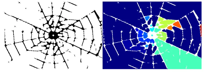
Figure: Error! No text of specified style in document..2 – Computed Binary Image and Label Image for Dense Rock
The figure 5.2.2 shows the dense rock fracture i.e. extract binary and label image.
Figure: Error! No text of specified style in document..3 – The Computed Binary and Label image for the Glass
Figure: Error! No text of specified style in document..4 – Computed Area between two similar Crack Image of Dense Rock
The area between two similar crack images of dense rock is shows in figure 5.2.4. The image shows that the average histogram of area has a high correlation factor. But the area varies a lot over the distribution. The average area has high similarity.
Figure: Error! No text of specified style in document..5 – Computed Area between two Similar Crack Image of Glass
Figure 5.2.5. Shows a very high correlation of fragment area generated from a brittle fracture like that of glass, as such materials have more consistent breaks due to low plastic deformation.
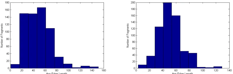
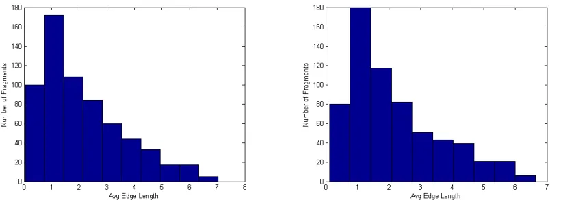
Figure 5.2.6 Average edge length of cracks in two dense rock crack images is comparable or similar. Materials like dense rocks has high break point, breaks immediately at the point of impact. Crack forwards with high attenuation and thus, crack length varies with each crack.
Figure: Error! No text of specified style in document..7 – Comparison of Avg. Edge Length of Cracks in Glass
Figure 5.2.7 shows a high correlation in two images histogram. In case of brittle fracture in glass, the edge generated forwards at a consistent rate apart from the force applied.
Figure: Error! No text of specified style in document..8 – Comparison of Junction Types in two Cracks on Dense Rock
Figure: Error! No text of specified style in document..9 – Comparison of Junction Type in two Cracks on Glass
Figure: Error! No text of specified style in document..10 – Comparison of Convex Area in two Cracks on Dense Rock
Figure: Error! No text of specified style in document..11 – Comparison of Convex Area in two Cracks on Glass
Figure: Error! No text of specified style in document..12 – Comparison of Convexity in two cracks on Dense Rock
Figure: Error! No text of specified style in document..13 – Comparison of Convexity in two cracks on Glass
Similar to convex area, a key shape factor is convexity which is highly similar in the two cases as shown in figure 5.2.12 and 5.2.13.
Figure: Error! No text of specified style in document..14 – Comparison of Perimeter in two cracks on Dense Rock
Figure: Error! No text of specified style in document..15 – Comparison of Perimeter in two cracks on Glass
In case of brittle fracture like the one in glass, the fracture propagation in glass material is more even and thus the histogram of perimeter shows that the two fractures are almost identical.
Figure: Error! No text of specified style in document..16 – Comparison of Circularity in two cracks on Dense Rock
Figure: Error! No text of specified style in document..17 – Comparison of Circularity in two cracks on Glass
Figure: Error! No text of specified style in document..18 – The two Similar Crack images on Dense Rock
Figure: Error! No text of specified style in document..19 – The two Similar Crack Images on Glass
The figures 5.2.18 and 5.2.19 shows the visual similarity of two different cracks on two different materials. Figure 5.2.18 shows the fracture on dense rock material and Figure 5.2.19 shows the fracture on glass surface.
Comparison Analysis
Based on our comparative studies, in the previous section, we have built a table, which generalizes overall result and helps in a much clearer understanding of our results.
Table: Error! No text of specified style in document..1 – The Summarization of Result in Form of Contribution
S No. Feature Distribution Correlation Avg. Similarity Contribution
1. Circularity High High Very High
2. Junction Type High High Very High
3. Convexity Medium High High
4. Avg. Edge Length Medium High High
5. Convex Area Medium Medium Medium
6. Perimeter Low High Medium
7. Area Low Medium Low
provide material induced signature patterns (like glass and mud pattern). Convex Area and Perimeter are important parameters but contributes very low to visual similarity.
V.CONCLUSIONANDFUTUREWORK
In our work, a set of statistical parameters have been tested to generate crack pattern with visual similarity to real crack as well has high statistical correlation to it too. The experimental results show the statistical parameters that are important in crack visual similarity as well as low correlated parameters are also found. In this thesis, the statistical parameters are studied only. In the future work, these parameters will be used to develop a tool to generate such patterns by mixing these parameters in different proportion.
REFERENCES
1. Lans, H., Data processing system and apparatus for color graphics display. U.S. Patent 4,303,986, 1981.
2. Trezopoulos, Demetri, and Kurt Fleischer. “Modeling Inelastic Deformation: Viscolelasticity, Plasticity, Fracture.” (ACM) 22, no. 4: 269-278,1988.
3. Norton, Alan, G. Turk, B. Bacon, J. Gerth, and P. Sweeney. “Animation of Fracture by Physical Modeling.” The Visual Computer 7, no. 4 :210-219, 1991.
4. Gibson, Sarah F., and Brian Mirtich. A Survey of Deformable Modeling in Computer Graphics. Technical Report, Mitsubishi Electric Research Laboratories, 1997.
5. Lin, X. B., and R. A. Smith. “Shape Growth Simulation of Surface Cracks in Tension Fatigued Round Bars.” International Journal of Fatigue 19, no. 6 : 461-469, 1997.
6. Hirota, Koichi, Tanoue YasuyukI, and Kaneko Toyohisa. “Generation of Crack Patterns with a Physical Model.” The Visual Computer 14, no. 3: 126-1.3,1998
7. O'brien, James F., and Jessica K. Hodgins. “Graphical Modeling and Animation of Brittle Fracture.” Proceedings of the 26th annual conference on Computer graphics and interactive techniques. ACM Press/Addison-Wesley Publishing Co., 137-146, 1999
8. Smith, Jeffrey, Andrew Witkin, and David Baraff. “Fast and Controllable Simulation of the Shattering of Brittle Objects.” Computer raphics Forum 20, no. 2 (2001).
9. Paquette, Eric, Poulin Pierre, and George Drettakis. “The Simulation of Paint Cracking and Peeling.” Proceedings of Graphics Interface. Canadian Human-Computer Communications Society, 10, 2002.
10. Hsieh, H. H., and W. K. Tai. “A straightforward and intuitive approach on generation and display of crack-like patterns on 3D objects.” Springer Berlin Heidelberg,.554-561, 2006.
11. Mérillou, S., and D. Ghazanfarpour. “A Survey of Aging and Weathering Phenomena in Computer Graphics.” Computer & Graphics 32, no. 2 : 159-174, 2008.
12. Iben, Hayley N., and James F. O'Brien. “Generating Surface Crack Patterns.”Graphical Models 71, no. 6: 198-208, 2009.
13. Muguerica, Lien, Carles Bosch, and Gustavo Patow. “Fracture Modeling in Computer Graphics.” Computer & Graphics 45: 86-100, 2014 14. L. Glondu, L. Muguercia, M. Marchal, C. Bosch, H. Rushmeier, G. Dumont, and G. Drettakis, “Example-based Fractured appearance,”
Comput. Graph. Forum, vol. 31,no.4, pp. 1547–1556, 2012.
15. H. Shin, C. Doumas, T. Funkhouser, S. Rusinkiewicz, K. Steiglitz, A. Vlachopoulos, and T. Weyrich, “Analyzing Fracture Patterns in Theran
Wall Paintings,” 2010.
16. L. Glondu, M. Marchal, and G.Dumont, “Real-Time Simulation of Brittle Fracture using Modal Analysis.” IEEE Trans.Vis. Comput. Graph.