Design and Development of DC-DC Resonant
Converter for DC Power Systems
Akshata Kulagod, Dr. Raghunath Ramaswamy
M.Tech Student, Dept. of EEE, BNMIT, Visvesvaraya Technological University, Bengaluru, India
Associate Professor, Dept. of EEE, BNMIT, Visvesvaraya Technological University, Bengaluru, India
ABSTRACT: The growing demand for higher power density and low profile in power converter designs has forced
designers to increase switching frequencies. Operation at higher frequencies considerably reduces the size of passive components such as transformers and filters. However, switching losses have been an obstacle to high frequency operation. In order to reduce switching losses, allowing high frequency operation, resonant switching techniques have been developed. These techniques process power in a sinusoidal manner and the switching devices are softly commutated. Therefore, the switching losses and noise can be dramatically reduced.
The proposed converter is operated at a switching frequency from 15kHz to 30kHz using DSP controller. The converter is validated with an experimental setup which delivers the output voltage of 28V and output current of 200A with desired efficiency of 87%. Simulation is carried out with input of 300V and 400V DC input and DC output of 28V, 200A at full load and no load. The power rating is 6KW. The prototype of the proposed converter is built. Prototype was conducted for 400VDC with 28V,200A output.
KEYWORDS: LLC Resonant converter; ZVS; ZCS; high frequency operation; power stage design
I. INTRODUCTION
DC-DC converters are power electronic circuits that convert a dc voltage to a different dc voltage level, often providing a regulated output. Imperfect switching is a major contributor to power loss in converters. Switching devices absorb power when they turn on or off if they go through a transition when both voltage and current are non-zero. As the switching frequency increases, these transitions occur more often and the average power loss in the device increases. High switching frequencies are otherwise desirable because of the reduced size of filter components and transformers, which reduces the size and weight of the converter.
There are many DC-DC converters such as Buck, Boost, Buck-Boost, CUK, SEPIC, Fly-back, Forward, Push-Pull converters in which switching is hard due to which power losses are more in the circuit. In resonant circuits, switching takes place when voltage and/or current is zero, thus avoiding simultaneous transitions of voltage and current and thereby eliminating switching losses. This type of switching is called soft switching, as opposed to hard switching in above mentioned circuits.
There are 2 types of conventional resonant converters. Series Resonant converter and Parallel resonant converter. These have got several limitations. Series resonant converter can achieve Zero Voltage Switching (ZVS) but fail to operate in Zero current switching (ZCS) due to frequency less than the resonant frequency. Also the output cannot be regulated for the no-load condition. As RL goes to infinity, Quality factor Q goes to zero. The output voltage is then
independent of frequency. However, the parallel converter is able to regulated the output at no load. For the parallel converter Q becomes larger as the load resistor increases, and the output remains dependent on the switching frequency. A drawback of the parallel converter is that the current in the resonant components is relatively independent of load. The conduction losses are fixed, and efficiency of the converter is relatively poor for light loads.
converter has been proposed. This series-parallel converter combines the advantages of both the series and parallel converters. The LLC-type resonant converter has many advantages over conventional resonant converters. First, it can regulate the output voltage over wide line and load variations with a relatively small variation of switching frequency. Second, it can achieve Zero Voltage Switching (ZVS) over the entire operating range and the light-load efficiency is relatively high. The resonant switch converter with zero-current switching has theoretically zero switching losses.
The proposed resonant converter is a DC-DC switching converter that includes resonant tank circuit actively participating in determining input to output power flow. This Resonant DC-DC converter is preferred over other conventional topologies due to its features like soft switching namely Zero-Voltage Switching and Zero-Current Switching, high frequency operation, high efficiency, smaller size, light weight, low component stress and reduced EM interference.
II. PROPOSED CONVERTER
A.Circuit Description
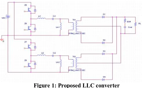
The proposed LLC resonant converters consist of three reactive elements Cr, Ls and Lp. One inductor is connected
in parallel to the load. Rectifier block is coupled to resonant inverter through a transformer. To maximize the usage of energy, rectifier block is configured as full wave rectifier that needs a center tap arrangement of transformer’s secondary winding. Full wave rectifier is preferred with a low voltage and high current output. In this converter power flow is controlled by the switch network by changing the switching frequency and phase shift control method is been used.
Figure 1: Proposed LLC converter
Since the resonant tank includes three reactive elements two resonant frequencies associated to this circuit. One is relating to condition of secondary winding conducting (constant voltage across it). Other is relating to secondary winding open (Ls and Lp are unified). LLC converter is normally operated in the region when input impedance of
resonant tank has inductive nature which increases with frequency. Implies the power flow can be controlled by changing the operating frequency. Reduced power demand produces frequency rise and increased power demand causes frequency reduction.
B. Operational Principle
The proposed converter topology is as shown in the figure 1. Switches Z1 and Z2 form one leg and connected to
LC resonant tank other inductor is connected across secondary side which reflects on primary, then center-tapped transformer with diode bridge rectifier is connected. Filter capacitor connected at the load side helps filter the ripple current. Switches Z3 and Z4 form other stage with same components connected as above. Diodes across switches are
connected for free-wheeling operation. Both the stages are phase shifted by 90 degrees. The dead-band between the top and bottom switches of same leg is maintained around 2usec. The input voltage is from 300Vdc to 400Vdc. Frequency
III. DESIGN CONSIDERATIONS OF POWER STAGE
A.LLC Converter
Sl.No Description Specifications 1 Output power rating 6KW
2 Input voltage range 300-400Vdc 3 Switching frequency 15kHz -30kHz 4 Output voltage range 28V
5 Output current 200A
TABLE 1: Input and output specifications for design
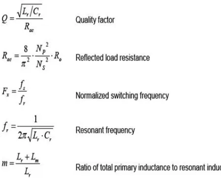
The design of components depends on variation parameters including gain, resonant frequency, quality factor, and ratio of primary inductance to resonant inductance. Hence these factors have to be taken care while designing. These factors are calculated as follows.
B. Transformer turns ratio for high switching frequency
Sl. No Description Specifications 1 Primary turns (NP1) 12
2 Secondary turns (NS1) 15 3 Secondary turns (NS2) 15
6 Transformer core AMCC 100
TABLE 2: Transformer specifications
C. Secondary Diode Rectification
An important step to achieve the best converter performance is to choose the right bridge and rectifier circuits. A full-wave rectifier requires diodes that are twice the voltage rating compared to a full-bridge rectifier. Since it has only two diodes it has half the total diode conduction losses compared to the full-bridge rectifier. A full-wave rectifier has two secondary windings, hence the resistance is doubled for the same winding area. In applications with low output voltages and high currents application, the full-wave is more common, because of lower total conduction losses and lower component count and cost.
Rectifier Diode and Capacitor Selection
Rectifier diode selection depends on the peak inverse voltage (VR) across it and output current.
S
R
PIV
V
1
.
25
Where ID is the diode rated DC current is the average output current which depends on the thermal rise in duration of
peak load condition.
O
D
I
I
3
O O O
V
P
I
Output capacitor selection depends on the ripple current.
2 2
av rms
ripple
I
I
I
With low ESR an electrolytic capacitor is selected. Output ripple voltage is
I
SP
ESR
The capacitor rating is increased on the basis of measured capacitor temperature rise under worst case loading and ambient temperature. ESR of the capacitor is multiplied with the secondary peak current to give the switching ripple voltage. Therefore it is important to select the low ESR capacitor to reduce the ripple voltage. Usually, selecting a high ripple current rated capacitor results in a acceptable value of ESR.IV. SIMULATION
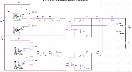
The proposed LLC DC-DC resonant converter topology is simulated using Orcad Pspice software. The simulation parameter is shown in the Table III. The simulation model includes VDC Source, Vpulse and IGBT switches with anti-parallel connected free-wheeling diodes, LLC resonant components, linear centre-tapped transformer and full-wave rectifier circuit with D1,D2,D3 and D4 diodes. Cout is the filter capacitor across the regulated output voltage for an DC input of 300V and 400V. The PWM pulse required for IGBT switches is given by the Vpulse with the required duty cycle for the given switching frequency. The simulation circuit is shown in Figure 4 and Simulation results are shown in Figure 5.
Sl. No Description Specifications
1 VDC voltage 300V-400V
7 Output Capacitor with ESR 10000uF, 9.4mE (5 no)
8 Rload 140mE
9 Switching Frequency (fsw) 15kHz-30kHz
TABLE 3: Simulation Parameters
TABLE 4: Simulation Result Tabulation
Figure 4: Simulation Circuit
Input RL
(Ohms) Vo
(V) Io
(A) Fs
(kHz)
Iripple
(A) 300V 140m 28 202 15.4 21A
300V 1.4 27.8 19.8 16.2 3.14A
300V 14 27.7 1.97 17.2 0.83A
400V 140m 28 200. 7
17.4 25.9A
400V 1.4 28.7 20.5 24.5 3.9A
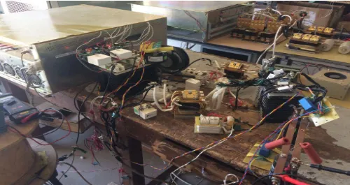
Figure 9: Hardware setup
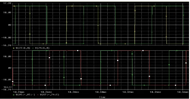
Figure 6: Results with 300V input at Full-Load
Figure 7: Results with 300V input at no-Load
V. RESULTS OF HARDWARE IMPLEMENTATION
The proposed resonant converter is implemented in the hardware as shown in Figure 9. As discussed in earlier section, PWM Controller generates initial PWM signal. Thus by switching action the converter provides 28V with 200A current for input voltage of 300V and 400V DC. The switching frequency is maintained from 15kHz to 30kHz. Output power rating is 6KW.
Figure 10: output voltage and output current Figure 11: Input voltage and Output voltage
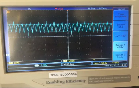
Figure 12: Ripple current of 16.8A
VI. CONCLUSION
The proposed DC-DC resonant converter is designed to operate with 300V and 400V input. Simulation is carried out for the proposed topology. The hardware prototype is build and the results are captured. The converter is observed to have output ripple current quite less with good output voltage regulation. The efficiency achieved is 87%.
REFERENCES
[2] Hyeong-Gu Han, Yeong-Jun Chai See-Yang Chai, and Roe-Yang Kim “A High Frequency LLC Resonant Converter with Wide Ranged Output Voltage using Adaptive Turns Ratio for Li-ion Battery Charger” 2016-IEEE vehicle power and propulsion conference (VPPC) in page number 1-6.
[3] Chih-Chiang Hua, Yi-Hsiung Fang, Cheng-Wei Lin “LLC Resonant Converter for Electric Vehicle Battery Chargers” 2016, IET power electronics in page 2369-2376.
[4] Shu Zhang, Jianping Xu, Sheng Zhao and Xiang Zhou “Bi-frequency control for LLC resonant converter with fast transient response” 2016, electronics letters in page 1710-1712.
[5] Utsab Kundu, Kalyan Yenduri and Parthasarathi Sensarma “Accurate ZVS analysis for magnetic design and efficiency improvement of full bridge LLC resonant converter” 2017, IEEE transactions on power electronics in page 1703-1706
[6] C.W.Tsang, C.Bingham, M.P.Faster, D.A.Stane, J.M.Leach “Battery Charger with a Capacitor-Diode Clamped LLC Resonant Converter” 2016, 8th IET international conference on power electonics, machines and drives (PEMD 2016) in page 1-6.
[7] Hwa-Pyeong Park and Jee-Haan Jung “Power Stage and Feedback Loop Design for LLC Resonant Converter in High Switching Frequency Operation” IEEE transaction on power electronics, 2016 in page 1-1.
[8] Mao Xingkui, Huang Qisheng, Ke Qingbo, XiaoYudi, Zhang Zhe, Michael A.E.Andersen “Grid-connected Photo-voltaic Micro-Inverter with New Hybrid control LLC Resonant Converter” IECON 2016- 42nd annual conference of the IEEE industrial electronics society in page 2319-2324.
[9] M.Radha and J.Srinivasa Rao “A Resonant Converter with LLC for DC-DC Converter Based Applications” International Journal for modern trends in Science and technology, Volume 1, Issue 1, September 2015.