University of Windsor University of Windsor
Scholarship at UWindsor
Scholarship at UWindsor
Electronic Theses and Dissertations Theses, Dissertations, and Major Papers
2013
Study of the Door Closing Performance of an Aluminum Door
Study of the Door Closing Performance of an Aluminum Door
Maurizio Mozzone
University of Windsor
Follow this and additional works at: https://scholar.uwindsor.ca/etd
Recommended Citation Recommended Citation
Mozzone, Maurizio, "Study of the Door Closing Performance of an Aluminum Door" (2013). Electronic Theses and Dissertations. 4922.
https://scholar.uwindsor.ca/etd/4922
This online database contains the full-text of PhD dissertations and Masters’ theses of University of Windsor students from 1954 forward. These documents are made available for personal study and research purposes only, in accordance with the Canadian Copyright Act and the Creative Commons license—CC BY-NC-ND (Attribution, Non-Commercial, No Derivative Works). Under this license, works must always be attributed to the copyright holder (original author), cannot be used for any commercial purposes, and may not be altered. Any other use would require the permission of the copyright holder. Students may inquire about withdrawing their dissertation and/or thesis from this database. For additional inquiries, please contact the repository administrator via email
STUDY OF THE DOOR CLOSING PERFORMANCE OF AN ALUMINUM DOOR
By
Maurizio Mozzone
A Thesis
Submitted to the Faculty of Graduate Studies
through the Department ofMechanical, Automotive and Materials Engineering
in Partial Fulfillment of the Requirements for
the Degree of Master of Applied Science
at the University of Windsor
Windsor, Ontario, Canada
2013
STUDY OF THE DOOR CLOSING PERFORMANCE OF AN ALUMINUM DOOR
by
Maurizio Mozzone
APPROVED BY:
______________________________________________ Jill Urbanic
Department of Industrial and Manufacturing Systems Engineering
______________________________________________ Daniel Green
Department of Mechanical, Automotive and Materials Engineering
______________________________________________ Jennifer Johrendt, Advisor
Department of Mechanical, Automotive and Materials Engineering
iii
DECLARATION OF ORIGINALITY
I hereby certify that I am the sole author of this thesis and that no part of this
thesis has been published or submitted for publication.
I certify that, to the best of my knowledge, my thesis does not infringe upon
anyone’s copyright nor violate any proprietary rights and that any ideas, techniques,
quotations, or any other material from the work of other people included in my thesis,
published or otherwise, are fully acknowledged in accordance with the standard
referencing practices. Furthermore, to the extent that I have included copyrighted
material that surpasses the bounds of fair dealing within the meaning of the Canada
Copyright Act, I certify that I have obtained a written permission from the copyright
owner(s) to include such material(s) in my thesis and have included copies of such
copyright clearances to my appendix.
I declare that this is a true copy of my thesis, including any final revisions, as
approved by my thesis committee and the Graduate Studies office, and that this thesis has
iv
ABSTRACT
When purchasing a product, and in particular when many different brands compete in the market, the first
impression will consistently affect a customer’s choice. When buying a car, the ease with which the doors
close, the speed and the sound of the closure must give the customer the impression of a quality car.
The recent stringent regulations on fuel economy and pollution have forced car makers to look for new
solutions to lower the fuel consumption of the vehicles of their fleet and meet the standards imposed. The
most obvious solutions to reach the target are the improvement in the efficiency of engines and the
reduction in vehicle weight. In the recent past, the use of aluminum (mainly in the form of alloy) in the
automotive industry has increased due to its lower weight with respect to steel, even if the higher costs
remain a big hindrance to the large-scale use of this metal. When dealing with door closing effort, the use
of aluminum introduces some issues that relate directly to the lower weight of the door and possibly to
other factors dependent on the different materials. The closing performance of the door is therefore
expected to change, and the variations in the contributors to the closing effort need to be analyzed and
discussed.
In this work, the door closing performance of an aluminum door and of a steel door of a C segment vehicle
are fully compared to study what changes, and to which extent, in the closing effort, due to the lighter alloy
used. Two means are used, the physical testing of the doors in the body shop with the EZ Slam technology,
and the simulation of the closing event with an existing closing effort predictive model. Particular focus is
put on the contribution of the check system to the closing effort and how its final profile affects the closing
v
DEDICATION
vi
ACKNOWLEDGEMENTS
vii
TABLE OF CONTENTS
DECLARATION OF ORIGINALITY ... iii
ABSTRACT ... iv
DEDICATION ... v
ACKNOWLEDGEMENTS ... vi
LIST OF TABLES ... x
LIST OF FIGURES ... xi
LIST OF ABBREVIATIONS/SYMBOLS ... xvii
NOMENCLATURE ... xix
1. INTRODUCTION ... 1
1.1 Automotive Door Assembly ... 3
1.2 Door latching mechanism and striker (or latch anchor) ... 6
1.3 Door check system ... 8
2. REVIEW OF LITERATURE ... 11
2.1 Lightweighting ... 11
2.1.1 Lightweight door solutions ... 14
2.1.1.1 Lightweight steel door concept ... 20
2.1.1.2 Advanced door concept ... 22
2.2 Door closing effort ... 23
2.2.1 Predictive models for door closing energy and closing speed ... 32
2.2.2 The DFSS project (Door Closing Effort T-method) ... 36
3 THEORETICAL BACKGROUND ... 37
3.1 Aluminum properties review ... 37
3.2 Physical phenomena behind Door Closing Effort ... 39
3.2.1 Air bind ... 39
viii
3.2.3 Seal compression ... 43
3.2.4 Door Weight ... 46
3.2.5 Hinge friction ... 46
3.3 Pendulum test for moment of inertia and center of gravity calculation ... 48
4 DESIGN AND METHODOLOGY ... 51
4.1 EZ Slam testing ... 51
4.1.1 Test set up ... 51
4.1.1.1 Slam test ... 54
4.1.1.2 Push test ... 55
4.1.1.3 Wiggle test ... 55
4.1.1.4 Sweep test ... 55
4.1.2 Test Outputs ... 56
4.1.2.1 Quality index ... 57
4.1.2.2 Speed vs. Angular position ... 58
4.1.2.3 Y vs. Z ... 59
4.1.2.4 Overslam vs. Speed ... 60
4.1.2.5 Overslam vs. Input impulse ... 61
4.1.2.6 Push Force vs. Y ... 62
4.1.2.7 Speed vs. Input Energy ... 63
4.1.2.8 Pulse energy vs. Angular position ... 64
4.1.2.9 Door raise vs. Angular position ... 64
4.2 The OU model... 65
5. ANALYSIS OF THE RESULTS ... 69
5.1 Testing Conditions ... 70
5.2 Comparison between Steel frame and Aluminum frame door closing effort ... 74
5.2.1 EZ Slam Testing ... 74
ix
5.3 Normal check vs. Prototype check Closing Performance on Aluminum ... 108
5.3.1 EZ Slam Testing Comparison ... 110
5.3.2 OU Model comparison analysis ... 124
6. SUMMARY ... 127
7 CONCLUSIONS AND RECOMMENDATIONS ... 130
BIBLIOGRAPHY ... 132
APPENDIX – UNCERTAINTY ... 135
x
LIST OF TABLES
Table 2-1: Aluminum and Steel predicted structural performance (in terms of deflection and
maximum load for several load cases) [10]. ... 17
Table 2-2: Material information for the reference door structure [14]. ... 20
Table 2-3: Material information for the Lightweight steel door concept [14]. ... 21
Table 2-4: Material information for the Advanced Door Concept [14]. ... 23
Table 3-1: Wrought Aluminum and Aluminum Alloy Designation [23]. ... 37
Table 3-2: Typical tensile properties for some of the most commonly used aluminum alloys in the automotive field [23]... 38
Table 5-1: Seal gap measurements. ... 71
Table 5-2: Steel vs. Aluminum door closing performance results. ... 75
Table 5-3: Doors' weight, inertia and center of gravity information for the steel door. ... 77
Table 5-4: Aluminum vs. Steel OU Model simulation. ... 105
Table 5-5: OU Model-EZ Slam comparison for the aluminum and steel tests. ... 106
Table 5-6: Check strap values of dimensions a, b, d and δ shown in Figure 5-38 for normal and prototype check straps... 109
Table 5-7: Aluminum normal check vs. custom check door closing performance parameters. .. 111
Table 5-8: Normal check vs. Prototype check OU Model simulation on aluminum. ... 124
Table 5-9: Ou Model vs. EZ Slam comparison of the aluminum tests with the prototype check. ... 126
xi
LIST OF FIGURES
Figure 1-1: Door frame exploded view. In the picture are listed all the components and the
reinforcements included in the door frame. ... 4
Figure 1-2: Weatherstrip seal system on door frame and car body [1]. The sealing system includes both the seals on the door and the ones applied to the vehicle body where the door fits when closed. ... 4
Figure 1-3: Exploded view of a front left door [1]. Specifically numbered from 1 to 4 are the following components: 1) Door trim panel, 2) Door module, 3) Door latching mechanism, 4) Door check system. ... 5
Figure 1-4: Door latching mechanism [1]. ... 6
Figure 1-5: Door striker (anchor) [1]. ... 8
Figure 1-6: Exploded view of the door check system. ... 8
Figure 1-7: Check arm section. In the picture it is possible to see the two springs and the two roller bearings that allow the motion of the door along the check arm. ... 9
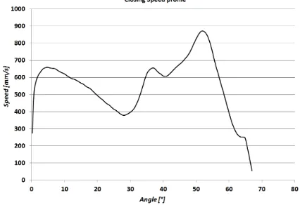
Figure 1-8: Typical closing speed profile of a door pushed by the user. The trend of the curve is dependent on check arm profile and the graph is to be read from right (fully open position) to left (fully latched position). ... 10
Figure 2-1: Total production costs for the three small cars analyzed in [7]: VW Lupo, Audi A2 and VW Lupo Hybrid. ... 13
Figure 2-2: Exploded view of the aluminum front door [10]... 15
Figure 2-3: Front door inner panel geometry [10]. ... 16
Figure 2-4: Front door STAR panel geometry [10]. ... 17
Figure 2-5: Bar chart showing the costs for the door solutions presented in [14] ... 23
Figure 2-6: Modal shape presented by the door in the simulation carried out in [15]. ... 25
Figure 2-7: Passenger compartment pressure compared to door shutting speed [19]. ... 29
Figure 2-8: Pressure rising rate compared to opening unit area [19]. ... 30
Figure 2-9: Different factors influences on pressure rise rate inside the cabin [19]. ... 31
Figure 2-10: Minimum shutting speed compared to opening unit area [19]. ... 32
Figure 2-11: Minimum shutting speed compared to moment of Inertia [19]... 32
Figure 2-12: Door closing/opening effort model with ADAMS [20]. ... 33
Figure 2-13: Seal modeling for air bind dampening evaluation [21]. ... 35
Figure 3-1: A diagram for a simplified air bind model [24]. ... 39
xii
Figure 3-3: A schematic diagram for latch effort [24]. ... 42
Figure 3-4: A schematic diagram of door/seal/body system [24]. ... 43
Figure 3-5: Seal compression under no slip condition [24]. ... 45
Figure 3-6: Force (L)/Compression(D) relation for Seal (per 100 mm) [24]... 45
Figure 3-7: A schematic diagram for door weight effort model [24]. ... 46
Figure 3-8: A schematic diagram for hinge friction effort model [24]. ... 47
Figure 3-9: Simple pendulum schematic diagram. A mass m placed at a distance L from the pivot point P oscillates due to the effect of the force of gravity [29]. ... 48
Figure 3-10: Schematic diagram of a compound (physical) pendulum [30]... 49
Figure 4-1: EZ Slam Door Unit [31]. ... 51
Figure 4-2: EZ Slam Cabin Unit [31]. ... 52
Figure 4-3: EZ Slam Body Unit [31]. ... 52
Figure 4-4: EZ Slam Base Station [31]. ... 53
Figure 4-5: Fully equipped door with the door and body units [31]. ... 54
Figure 4-6: Input energy pie [31]. ... 56
Figure 4-7: Dissipation energy pie [31]. ... 57
Figure 4-8: Quality index given as output of an EZ slam session. ... 58
Figure 4-9: Speed vs: Angular Position graph example [31]. ... 59
Figure 4-10: Z vs. Y trajectory graph [31]. ... 60
Figure 4-11: Overslam vs. Speed graph [31]. ... 60
Figure 4-12: Overslam vs. Input Energy graph [31]. ... 61
Figure 4-13: Push force vs. Displacement graph [31]. This graph is the main output of the static push test together with the value of minimum overslam. ... 62
Figure 4-14: Closing Speed vs. Pulse Energy [31]. ... 63
Figure 4-15: Pulse energy vs. Angular position graph [31]. ... 64
Figure 4-16: Door raise vs. Angular position graph [31]. ... 65
Figure 4-17: Constant and solution parameters input. ... 66
Figure 4-18: Door seals geometry shown in the three coordinate planes in the OU Model. ... 67
Figure 4-19: Output results from a simulation performed with the OU Model as an example. .... 68
Figure 5-1: Points used for seal gap measurements ... 70
Figure 5-2. Coordinate system used by EZ Slam. ... 74
xiii
Figure 5-4: Direct visual comparison of the energy inputs for the tests performed on the steel and
on the aluminum doors... 76
Figure 5-5: Minimum closing speed vs. Angle graph. ... 79
Figure 5-6: Minimum average closing speeds. ... 79
Figure 5-7: Energy sink contributions during the closing action of the steel door. Each bar corresponds to the energy values relative to one of the tests performed on the steel door and used to create the average values presented in Table 5-2. ... 80
Figure 5-8: Energy sink contributions during the closing action of the aluminum door. Each bar corresponds to the energy values relative to one of the tests performed on the aluminum door and used to create the average values presented in Table 5-2. ... 80
Figure 5-9: Steel vs. Aluminum Closing sweep force comparison (applied by the check to the door). The sinusoidal shape is due to the corrugated profile of the check arm. ... 81
Figure 5-10: Average closing sweep forces of the tests conducted on the steel and on the aluminum frame. ... 82
Figure 5-11: Steel vs. Aluminum Closing Sweep energy comparison. The shape of the energy curves depends on the shape of the force curves. ... 83
Figure 5-12: Average closing sweep energies for the steel and the aluminum door tests. ... 83
Figure 5-13: Aluminum vs. Steel Opening Sweep Force comparison. As in the case of the closing sweep force graphs, the sinusoidal shape of the curves is due to the corrugated profile of the check arm. ... 84
Figure 5-14: Average opening sweep forces. ... 85
Figure 5-15: Aluminum vs. Steel Opening Sweep Energy comparison. ... 85
Figure 5-16: Average opening sweep energies. ... 86
Figure 5-17: Production check closing force for the three configurations tested (Supplier tester). ... 87
Figure 5-18: Production check opening force for the three configurations tested (Supplier tester). ... 87
Figure 5-19: Opening and closing check forces comparison (Supplier tester). The force is expressed as a function of the opening angle. ... 88
Figure 5-20: Trace tester vs. EZ slam forces comparison for opening and closing actions. The upper half of the graph is referred to the opening action, the lower half to the closing action. ... 89
xiv
Figure 5-22: Closing energies comparison between the Supplier's tester measurements on the
steel door setup and the EZ Slam measurement on the steel door. ... 91
Figure 5-23: Closing energy comparison between the Supplier's tester measurements on the aluminum door setup and the EZ Slam measurement on the aluminum door. ... 92
Figure 5-24: Closing force and closing energy for the flat check configuration The energy is the integral of the force. ... 92
Figure 5-25: Trace tester vs. EZ slam opening energy comparison. The curves of the energy derive once more from the force curves. ... 93
Figure 5-26: Pressure rise inside the cabin in function of Time. The peak of the curve is reached at time 0 when the door is fully closed and at maximum overslam. ... 95
Figure 5-27: Average pressure rise in the cabin. ... 95
Figure 5-28: Pressure vs. Overslam trend for Steel vs. Aluminum comparison. The pressure is greater, for the same value of overslam, for all the aluminum tests as opposed to the steel tests. 96 Figure 5-29: Average pressure vs. overslam curves. ... 96
Figure 5-30: Value of the overslam as a function of the closing speed for the steel and aluminum tests. The same overslam was reached by the aluminum door with an higher speed. ... 97
Figure 5-31: Average overslam vs. speed curves. ... 97
Figure 5-32: Speed vs. Pulse comparison graph for steel and aluminum. ... 98
Figure 5-33: Average speed vs. pulse curves. ... 99
Figure 5-34: Static compression load curves for the steel and the aluminum doors tests. ... 100
Figure 5-35: Average static compression load curves. ... 100
Figure 5-36: Door rise of the aluminum door during the closing event. ... 102
Figure 5-37: Door rise of the steel door during the closing event. ... 103
Figure 5-38: EZ Slam quality index of the three steel door tests. Black: steel test 1, Red: steel test 2 and Blue: steel test 3. ... 104
Figure 5-39: EZ Slam quality index for the four aluminum door tests. Black: aluminum test 1, Red: aluminum test 2, Blue: aluminum test 3, Green: aluminum test 4. ... 104
Figure 5-40: Check arm dimensions a, b, d and δ after last detent of the check arm [1]. ... 108
Figure 5-41: Direct visual comparison of the energy sink contributions for the tests performed on the aluminum door with the two different check straps. ... 112
xv
Figure 5-43: Energy sink contributions during the closing action of the aluminum door for the two tests performed with the custom check. The “CA” refers to close assist and indicates the tests
performed with the prototype check. ... 113
Figure 5-44: Opening Sweep energy comparison for the normal and the custom check. The plot comes from the numerical integration of the opening sweep force curves from the almost closed position to the fully open position. ... 114
Figure 5-45: Average opening energy curves. Labeled in green is the curve of the custom check tests and in blue the curve of the normal check tests.. ... 114
Figure 5-46: Closing Sweep energy comparison for the Production and the Custom checks. The full open angle is grater for the custom check (CA) because of the absence of the check arm hard stop. ... 115
Figure 5-47: Average closing sweep energy curves. ... 115
Figure 5-48: Closing force comparison for the production and the prototype check (Supplier's tester). ... 116
Figure 5-49: Closing energy comparison for the production and the prototype check (Supplier's tester). ... 117
Figure 5-50: Force pulse vs. Angle for the two different check straps. The impulse starts approximately 6 degrees earlier for the custom check due to the greater swing allowed. ... 118
Figure 5-51: Average force vs. angle curves. ... 119
Figure 5-52: Speed vs. Input pulse curves for all the tests performed on the aluminum door with the normal check (blue curves) and with the prototype check (green curves). ... 120
Figure 5-53: Average Speed vs. Input pulse curves for the tests performed on the aluminum door with the normal check (blue curve) and with the prototype check (green curve). ... 120
Figure 5-54: Minimum closing speed vs. Angle comparison for the Production and Custom check. ... 121
Figure 5-55: Average minimum closing speeds. ... 121
Figure 5-56: Door rise of the aluminum door with custom check during the closing event. ... 123
Figure 5-57: Torque characteristics of the normal check and of the prototype check ... 125
Figure A-1: Intervals of relative and absolute variations of the minimum closing speed curves for the steel and aluminum tests. ... 136
Figure A-2: Intervals of relative and absolute variations of the Overslam vs. Speed curves for the steel and aluminum tests. ... 137
xvi
xvii
LIST OF ABBREVIATIONS/SYMBOLS
cseal: coefficient used to correct the seal compression model in the OU Model. cm: door center of mass position (OU Model).
CLD: compression Load Deflection. DFSS: Design For Six Sigma. DP: Dual Phase.
dlatch: latch displacement (OU Model). dseal: compression distance (OU Model).
̅: normalized compression distance.
Eair: energy sunk by the air bind effect during closure (OU Model).
Elatch: energy sunk by the latch-striker system during door closure (OU Model). Eg: gravitational potential energy.
Ehinge: energy sunk by the friction at the hinges during closure (OU Model).
Eweight: energy that will help door closure due to the weight of the door (OU Model). Flatch: latch force (OU Model).
fseal: seal force (OU Model).
FAST: Ford Advanced Super Plastic Forming Technology. HSLA: High Strength Low Alloy.
HVAC: Heating Ventilation Air Conditioning. IAdoor: door’s moment of inertia (OU Model).
ICM: moment of inertia of an object around its center of mass. IQS: Initial Quality Study.
g: acceleration of gravity.
h: distance between the upper and lower hinges (OU Model). l: length of a seal segment (OU Model).
̅: normalized compression force lseal: seal lip interference (OU Model).
klatch: constant of proportionality between latch force and latch displacement (OU Model). MDO: Multidisciplinary Design Optimisation.
xviii
̅̅̅̅: change in pressure inside the vehicle cabin due to door closure (OU Model).
PA/PE: polyamide/polyethylene PP100: Problems per 100 vehicles. QPF: Quick Plastic Forming.
rcm: distance of the door center of mass from door hinge (OU Model). rh: door hinge pin radius (OU Model).
rlatch: distance of the latch system from door hinge axis (OU Model). S: vent hole’s area.
SD: door area.
SPF: Super Plastic Forming.
STAR: Simplified Total Aluminum Reinforced.
Tair: torque opposing to door closure due to the air bind effect (OU Model).
Thinge: total contrasting torque given by the friction at the door hinges during closure (OU Model). Tweight: torque due to door weight helping door closure (OU Model).
Tseal: torque opposing to door closure exerted by all the seal segments (OU Model). T’seal: corrected seal torque value (OU Model).
ULSAC: Ultra-light Steel Auto Closure. UTS: Ultimate Tensile Strength.
Vc: vehicle cabin volume.
vvent: velocity of air at the vent (OU Model). YS: Yield Strength.
ρatm: density of air at atmospheric pressure (OU Model). μh: hinge friction coefficient (OU Model).
ω: door’s angular velocity.
θc: door opening angle at which the seals start to compress (OU Model).
xix
NOMENCLATURE
- Airtight Integrity: closure or fitting that prevents the passage of air.
- Latch: component in the door assembly that allows the complete closure of the door hooking to the striker.
- Lightweighting: term to indicate the decrease in weight of the automotive structures or subsystems.
- Fully latched position: position of the door in which the latching mechanism is fully engaged. The door can be closed in a primary position (the latch is partially engaged so the door cannot open but it is not fully closed), and in a secondary position, corresponding to the fully latched position.
- Overslam: distance the door travels past the final rest position during closure in order to reach a complete latching. Overslam depends on the closing speed, the higher the speed the higher its value.
- Residual Energy: is the energy retained by the door system once the door is shut; if the kinetic energy of the closing door goes to zero before the latched position is reached, the door will not close. A certain amount of kinetic energy (minimum kinetic energy) is needed in order to fully latch the door.
- Seal Gap: it is an indicator of the amount of compression of the seals on the body when the door is fully latched.
1
1.
INTRODUCTION
Car makers have to deal with many different problems, often related to governmental
regulations, standards to be respected and safety issues. Another of the main factors
leading car companies’ choices is customers’ perception and impression on the quality of
the product sold.
Door closing performance is strictly related to this last aspect. After the visual impact the
vehicle has on the customer, when the customer buys a car the doors are most likely the
very first part of the vehicle he/she comes into contact with, to access and exit the
vehicle. One of the customer’s very first impressions about the quality of the car will then
be given by the behaviour of the doors when opening and closing, the speed and the
energy that are required to obtain a full latching, and the sound that the door makes when
closed by the user. Moreover, an incomplete closure of the door or an excessive speed
required to fully latch it might give rise to safety issues that must be avoided or to
unpleasant sounds during closure.
Another point of focus for car companies is represented by the lightweighting of
structures, required in order to lower the total weight of the vehicle to reduce fuel
consumption and pollutants emissions. One of the most obvious ways to reduce the
weight of a car (even though not yet sufficient to solve the problems of fuel consumption
and excessive pollution levels) is to use lightweight materials (e.g. aluminum and
magnesium alloys) to replace the use of steel in components such as the frame or the door
panels (side doors, trunk lid, and hood). The use of doors built with an aluminum frame is
therefore of great interest for car companies that must take into account the effects that
the use of a much lighter door might have.
The purpose of this study is to evaluate the consequences, in terms of door closing effort,
of the use of a lightweight aluminum door in place of a common steel door, analyzing all
the differences that the use of a different material creates in the door closing process and
understanding which actions might be taken, in case of the worsening of the performance,
to obtain acceptable door closing performance. The term closing effort can be intended as
2
that the customer needs to put in order to shut the door (which, as explained later in the
document, does not coincide with the total effort). The best way to perform such a study
is to have the values of the parameters pertaining to door closing effort both for a steel
frame and for an aluminum frame, in order to be able to directly compare all the
contributions that hinder or help the door closure and detect the factors that change the
most with the change of frame material. Once the values of the energy contributions are
known from the tests, it is possible to understand on what parameters it is necessary to
work either to lower the value of the energy sinks during closure or to increase the
amount of energy given by the factors that help the user in closing the door. To obtain all
the parameters related to the effort, the two doors will be tested with the same equipment
(provided by EZ Metrology and described in Chapter 5), testing first the steel door and
then swapping all the components from the steel frame onto the aluminum frame in order
to maintain all the door’s features and changing only the frame material. Using an
available door closing predictive model, the OU (Oakland University) Model described in
Chapter 5, the parameters relative to the two doors will be input to the model to perform
an additional comparison of the doors and to correlate the results. Both methods have
assumptions and approximations in the calculations, but the results of the two
comparisons (between steel and aluminum frames) should point in the same direction, as
the two doors will be treated exactly in the same way during the testing and the running
of the predictive model.
The document is subdivided into 6 main sections. In Chapter 2 the research work found
in the literature about the lightweighting of automotive structures, in particular of side
doors, and the use of aluminum in the automotive industry is presented together with past
work done on door closing effort. In Chapter 3 a brief review of the theoretical
background and of the physical phenomena behind door closing effort is done. Finally,
Chapters 4 and 5 focus on the methodologies that have been used to evaluate the door
closing effort and on the results obtained with the physical tests on the doors Chapter 6
presents the conclusions, summarizing the results obtained and suggests the future work
to be done to improve the results of the research.
The main components of the door assembly are here briefly described to allow an easier
3
1.1
Automotive Door Assembly
An automotive door can be divided into eleven main sub-assemblies, each of which is
made up of several other parts. In this section a brief description is given of the main
parts of the door that will be considered in the following sections in order to facilitate the
understanding of the discussion and analysis of the results.
- Door frame: composed of the outer and inner panels and an anti-intrusion beam
for side crash protection. As described in the literature review section, the frame
assembly can change and may have different configurations in terms of inner
panel, hinge and belt reinforcements and anti-intrusion safety elements. The door
frame exploded view is shown in Figure 1-1.
- Inner panel: the exterior panel of the door assembly pointing towards the inside of
the cabin; includes the armrest, the handle and other inserts. The trim panel is
attached to the door frame by push pins, and it is shown in Figure 1-3, item 1.
- Door mechanism: includes the door lock and latching system, the latch support
and the latch anchor (placed on the body).
- Window system: includes the glass and the window motor and regulator.
- Sealing system: all the weather strips and the moldings that provide insulation
from sound and external agents. The seal system is divided between the seals
attached to the door and the seals attached to the car body. The seals on the door
frame and car body are shown in Figure 1-2.
- Hinges: upper and lower hinges situated on the door, they are coupled with the
hinges mounted on the body and allow the door to swing.
- Power system: it is made up of the wiring harness.
- Mirror system: includes the mirror glass, frame, external shell, attaching plate,
wiring harness and all the insulation.
- Power controls: include all the door switches.
- Speaker system: includes the speaker and wiring harness connection to the
4
- Function carrier (or module): allows the installation of all the power controls,
wiring harness and speaker in the door. The component is screwed directly to the
door frame’s inner panel (Figure 1-3, item 2).
An exploded view of a front left door is shown in Figure 1-3
Figure 1-1: Door frame exploded view. In the picture are listed all the components and the reinforcements included in the door frame.
5 .
6
1.2
Door latching mechanism and striker (or latch anchor)
Figure 1-4: Door latching mechanism [1].
Each door of a car is equipped with a latch to lock the door to the body in the closed
position. The other main use of the latch is to prevent unauthorized entry to the vehicle.
The latch system (shown in Figure 1-4) also has to perform to a specific level during car
accidents, having a minimum strength that reduces the possibility of occupants of being
ejected during a crash. Tests are performed to verify the minimum strength of door latch
(or, better, of the latch-striker combination) in a longitudinal direction (parallel to the
direction of vehicular travel) and in a lateral direction (perpendicular to the vehicle’s
direction of travel). The requirements involve a minimum performance in terms of loads
both in the primary position (fully latched door) and in the secondary position (partially
engaged system) [2]. Since the latching system is exposed to the environment, it must
also withstand exposure to water, ice, dust and dirt, and also to very high and very low
temperatures. The system is placed as shown in Figure 1-3, item 3. The latching system
7
it is usually coupled to electromechanical systems of rotation or rotation-translation. The
latch can be either manually operated or powered by a motor and it usually consists of
rigid and elastic elements (articulated bars, cams, springs and levers) and an actuator in
the form of a locking lever. The latch is connected to the inside and outside handles via
attached rods and cables [3]. Over the years the latching system has evolved and many
different features were added to the mechanism increasing its functionality but also its
complexity and weight. As explained in [4], in the 1970’s central locking was added
(allowing the simultaneous unlocking of all the doors with the push of a button) while in
the 1980’s remote keyless entry was introduced (thanks to the use of radio frequency
transmitters and receivers placed in the key and in the car). The introduction of “Super
Locking” allowed an improvement in safety, neutralizing the interior windowsill control
knob and all of the door handles to prevent theft. Other features that have been introduced
or are in the design phase are the door Passive Entry, that allows the recognition of the
owner and the unlocking of the door even before he/she presses the button on the key, the
Electric Child Safety (that neutralizes the inside handles of the rear doors to prevent
accidental openings by children) and the Power Closing and Release, that allow a tighter
closure of the door during vehicle motion to reduce wind and road noise, and an
automatic release of the claw of the latch to open the door. The main issues regarding
these improved features are, as said before, the increase in weight of the system and also
the increased costs. Usually the mechanical solutions that allow all the newly introduced
functions require electric powered motors that include compressors, solenoid valves,
ECUs and extensive wiring that can add as much as 7 kg of weight to the system.
Moreover, these systems are usually complex and time consuming to assemble. However,
solutions are available, such as the one presented in [4], that allow all the functions
requested in a state-of-the-art latching system while maintaining lower prices (thanks to
the use of fewer motors, drivers, wires, and connectors), lower weight (thanks to the
simpler system used), smaller packaging envelope, easier installation and system design,
and flexibility.
The latch locks the door by hooking to the striker (or latch anchor), shown in Figure 1-5,
that is placed on the car body. When trying to reach the best fitting of the door on the
8
striker can be left loose, the door is shut and the striker is left to adjust itself in order to
provide the best closure. The striker is then tightened in its final position.
Figure 1-5: Door striker (anchor) [1].
1.3
Door check system
The check strap, presented in the exploded view in Figure 1-6, is a system connecting the
door to the car body and placed as shown in Figure 1-3, item 4.
9
The shape of the component is symmetrical with respect to the horizontal axis and the
forces are exerted on the check arm through two springs and two rollers. As the door is
moved along its arc trajectory, the rollers travel forwards (during closing) and backwards
(during opening) on the check arm following the profile of this last component. A section
of the check strap is shown in Figure 1-7.
Figure 1-7: Check arm section. In the picture it is possible to see the two springs and the two roller bearings that allow the motion of the door along the check arm.
The left-hand side of the picture shows the clevis bracket that connects the check link to
the pillar while the “case” that contains the springs and the rollers is screwed to the door.
The check arm has three indents corresponding to positions at which the door will stop if
it is operated sufficiently slowly. The presence of these indents causes the closing speed
profile that is shown in Figure 1-8. The door is pushed by the user up to a certain angle
and then it is let go to close by itself. While the user pushes the door the speed increases,
while it starts decreasing when the user lets go and the roller bearings of the check system
start “climbing” the profile. Every time the check arm’s profile shows a slope, the speed
of the door increases; the speed increase is particularly evident during the last slope of the
check arm, from approximately 30 degrees of opening angle to the latched position. This
last part of the profile of the check is defined close assist. The plot in Figure 1-8, that will
10
because it represents the door closing phenomenon that starts when the door is in the
fully open position (in the example 67 degrees) and ends when the door is fully latched.
When the door is opened the springs store energy, which is released during closure.
The explanation provided describes why the energy contribution of the springs is
considered positive on closing the door and negative during opening. During the portion
of the profile where the slope increases (the rollers “climb” the check arm) the springs are
compressed and store energy that is released during the motion on the portion of the
profile showing a negative slope.
The entire weight of the door is carried by the hinges; the clevis bracket that connects the
check arm to the car body has a small amount of vertical float allowed and so none of the
weight is carried by the check, that has very little rigidity in the up/down direction.
Figure 1-8: Typical closing speed profile of a door pushed by the user. The trend of the curve is dependent on check arm profile and the graph is to be read from right (fully open position) to left
11
2.
REVIEW OF LITERATURE
2.1
Lightweighting
The regulations on fuel economy, which have become more stringent in the latest period,
force car makers to develop different fuel-saving technologies that allow them to meet
the standards imposed by the government. These standards are expected to increase in
severity even more in the next years; an example would be the 54.5 mpg as average fuel
economy required on cars and light trucks by 2025.
From very recent surveys [5], [6], two main technology trends will probably be most
helpful for automakers to reach their goals in terms of fuel saving: the use of lightweight
materials, and engine downsizing. Other possible ways to be considered are the
integration of different components in order to reduce the overall mass of the vehicle
(design optimization), improvements in the aerodynamic efficiency of the vehicle and
increases in thermodynamic efficiency of engines. During the last IEEE iTec conference
on electrification and transportation held in Dearborn, Michigan, in June 2013, it was
pointed out how the lightweighting of structures and the engine downsizing will probably
not be sufficient to reach the targets on fuel economy and low pollutant emissions, but
they will need to be coupled to the use of hybrid propulsion systems such as electric
motors. This solution is expected to allow also an improvement in vehicle performance.
Fuel economy concerns and changing government regulations are driving the need to
introduce lightweight alternatives for vehicle components. The areas that will probably be
the most targeted by lightweighting will be car body and powertrain, followed by the
chassis. The reason for this lies in the fact that these areas are all characterized as heavy
systems and therefore offer the greatest possibilities for weight reduction: engine and
chassis each weigh about 20-30% of the total vehicle weight and auto-body weighs
approximately 40-50% of total weight, leaving a 10% for the remaining parts. Amongst
the available lightweight materials, aluminum and composites are thought to be, at least
at the moment but probably also for several years more, the best choices to obtain a
consistent decrease in the weight of components and consequently of the vehicles, but
12
Starting back in 1994, significant vehicle weight reductions were achieved with the
introduction of high strength steel (mostly in the framework) that allowed an increase in
structural resistance and stiffness together with a decrease in weight of around 12-13%.
These benefits were realized due to the higher mechanical properties of high strength
steel. However, cost-related issues arose due to the more expensive shaping techniques
required, the better anti-corrosion treatments needed and, in general, the higher cost of
the high-strength steel with respect to common steel. The aluminum alloys have
interesting qualities such as low density, good mechanical properties and high corrosion
resistance. A comparative study in 2001 of Kelkar et al. [7] analyzed the production costs
relative to three small cars; one was built entirely in steel (VW Lupo), one built with an
hybrid steel-aluminum structure (VW Lupo Hybrid, built with doors, bonnet and fenders
made of aluminum) and a last one designed to be a fully aluminum car (Audi A2).
Although as highlighted before aluminum has a much lower density than steel (and thus
lower weight) and satisfies the stiffness and torsion requirements for automotive
components, the cost by weight is much higher than that of steel and therefore requires
optimized design and production of the components in order to be cost effective and
maintain the advantages of the weight saving. In this research the Technical Cost
Modeling (TCM) of MIT’s Material System Laboratory was used to break down the total
cost into its components (material parameters, processing parameters and production
parameters) in fixed and variable costs.
With respect to the steel version, the hybrid version of the Lupo was more expensive due
both to the higher material costs and to the added tooling costs required to stamp all the
parts. The problems in stamping aluminum involve a tendency of the aluminum to tear,
thus requiring slow stampings and extra hits. Even though neglected in the research,
another additional cost to be considered was the joining of the aluminum closures to the
steel body. The Audi A2 (full aluminum) was comparable, in cost, with the Lupo Hybrid;
this was possible because the A2 was designed to be a fully aluminum car and allowed
the spaceframe to be optimized using large, cost effective castings instead of aluminum
stampings. The total production costs analyzed in the research are presented in Figure
13
together with a complete review of the design and manufacturing aspects with respect to
steel to obtain a cost-effective process.
Figure 2-1: Total production costs for the three small cars analyzed in [7]: VW Lupo, Audi A2 and VW Lupo Hybrid.
An even greater weight reduction can be obtained with magnesium alloys, characterized
by a density of two-thirds that of aluminum, but showing a lower resistance at high
temperatures.
Looking ahead in the future however, the results of the surveys have shown that the
greatest weight reductions will probably come from the use of a mixed-materials design
approach more than from the use of a single lightweight material.
The costs of the modifications needed on the vehicles of their fleets and of the research
and development stages that are necessary to introduce the use of lightweight materials
into mass production represent a big investment for car makers, but the cost savings that
will result from the lower fuel consumption are thought to outweigh those costs. Despite
this fact, the increase in costs probably still represents the biggest challenge for industries
14
2.1.1 Lightweight door solutions
Some research was done in 1993 to study the feasibility of the production of a door with
die cast magnesium and an extruded aluminum frame using a common steel door design
[8]. The steel door used for comparison was that of a mid-size 4 doors sedan of
medium-high production volume (> 100000 units). The proposed solution included a one-piece
magnesium die casting to consolidate inner panel, upper frame, hinge, lock and waist
reinforcements, glass window channels and hinges. For the remaining parts (outer panel,
side intrusion beam and window frame) aluminum was chosen. High pressure die casting
was chosen for the magnesium parts because of its good design flexibility, dimensional
stability and repeatability and overall integrity. The proposed attachment method of the
door panel was a flange hemming operation (the operation of folding a panel over another
panel, often with the use of a binding element). All the internal components of the door
were installed in the exact same position as in the steel frame. From the predicted
deflections the magnesium door met the stiffness requirements apart from localized
points for the lower torsional rigidity case. From the business analysis done in the
research, with a 40% weight saving with respect to the steel door, an estimated unit cost
saving of $14.66 may be reached with the magnesium/aluminum solution. Another study
was carried out in 2006 by Luckey & al. [9] to investigate the feasibility of superplastic
forming (SPF) to reduce the cost of the manufacturing of aluminum sheets and achieve
weight savings of the order of at least 30-40% with respect to conventional steel. The
superplastic forming allows to achieve large strains to failure and low flow stresses in the
panels. It is typically accomplished with a single sided die (less expensive than matched
tooling) where the sheet is heated to a high temperature and gas pressure is applied to
push the sheet into the tool. Thanks to aspects such as flexible automation for blank
heating and loading, automated part extraction and cooling and use of CAE to determine
optimal forming parameters that allow a decrease in the overall cycle time, the Ford
Advanced Super-Plastic Forming Technology allows cost-effective, higher volume
applications of the SPF. The castings, stampings and extrusions necessary to produce a
common door architecture were substituted with fewer, less-expensive parts formed with
15
In 2007 Schrot & al. [10] studied a new design of aluminum front and rear doors using
quick plastic forming (QPF) and a multi-purpose reinforced panel named “STAR”. The
exploded view of the front door is shown in Figure 2-2. The Quick Plastic Forming
process was developed by General Motors as a hot sheet blow forming technology to
allow the manufacturing of complex aluminum shapes at automotive volumes (up to
100000/yr) [11].
Figure 2-2: Exploded view of the aluminum front door [10].
This type of technology was targeted at forming an automotive panel from a
cost-effective aluminum sheet with tooling appropriate for high-volume production.
High-volume manufacturing capability was sought. To support the high High-volume of automotive
production the automation of the forming cells was needed. The hydraulic press with
heated, insulated tool system offered advantages in terms of performance and flexibility.
The higher costs coming from a greater complexity of the system were amortized over a
larger number of parts produced. In the QPF process, after the aluminum sheet is brought
to the forming cell in blanked and lubricated form, a conduction preheater does the blank
preheating outside the press. The cycle time is reduced thanks to an automated material
handling. The formed panels can be removed from the tool in a repeatable manner thanks
16
Completing the structure of the door designed in [10] were the inner and the outer panels.
The outer panel thickness was increased by 50% with respect to the steel counterpart in
order to provide the required rigidity and the inner panel replicated the steel door inner
panel, with the same geometry, in order to fit the trim panel without modifications.
Maintaining the same outer dimensions, the greater thickness of the panel was driven
toward the center of the door section. The main innovation in [10] was the replacement of
the conventional impact beam of the door with an open-ended multifunctional Simplified
Total Aluminum Reinforced panel (STAR), that allowed the forming in a simple
single-piece tool. The front door inner panel and STAR panel are shown in Figure 2-3 and
Figure 2-4.
Figure 2-3: Front door inner panel geometry [10].
The corrugated geometry of the STAR panel was designed based on the computer
modeling of the static and dynamic performance of the panel; the panel was designed to
allow high-volume assembly with traditional assembly fixtures. A separate hinge
reinforcement was added. The weight saving with the new front door aluminum structure
with respect to its steel counterpart was of 5.7 kg. In terms of performance of the
aluminum door, Table 2-1 summarizes the results (for deflection and maximum load for
several load cases) predicted in [10] making a comparison with the steel door. The
structural performance of the aluminum door was satisfactory and almost all deflection
metrics met the target values; a very large deflection at the upper B-pillar position was
17
door design. During the dynamic loading case (dynamic side impact test) the STAR panel
was found to distribute the load along the entire periphery of the door below the beltline.
Figure 2-4: Front door STAR panel geometry [10].
Suggestions for an improved door design in [10] were to increase header rigidity and
reduce door mass by downgauging the panels, as for many load cases the aluminum door
was found to perform even better than the steel prototype.
18
Amongst the investigations aimed at reaching lower weight doors using steel, in 2000 the
UltraLight Steel Auto Closure Consortium achieved a significant 22% weight saving over
the lightest benchmark framed door at that time.
The results were achieved by using high and ultra-high strength steels combined with
technologies such as tailored blanks and hydroforming. Even greater achievements and
further mass reduction were reached using sheet hydroforming for the door outer [12].
When designing a light vehicle, in order to achieve an optimum solution the constraints
coming from three main areas need to be considered simultaneously: design,
manufacturing and materials. Zuidema [13] defines the process that leads to the correct
management and interaction between these three aspects, that starts with the
determination of the mechanical properties combination to achieve the required
performance in strength, energy absorption and stiffness of the component. The second
step is to determine the requirements that assure the manufacturability of the component,
and thus mechanisms like work hardening and thinning during manufacturing need to be
taken into account. Once the first two aspects are defined, the steel grade development
team is in charge of finding the suitable microstructure of the material that will achieve
the desired properties. Finally the thermomechanical processes needed to reach the
necessary microstructure are defined. Zuidema analyzes how, in the door area of the
safety cage, components like the vertical pillars, the roof and the floor cross members
need to resist bending collapse and axial buckling. The suggested steel grades for the
safety cage components are therefore dual phase grades up to 1180 MPa ultimate tensile
strength (UTS) and other complex phase or martensitic and press hardening grades of
similar UTS.
In his work Zuidema presents also the design of a door in DP490 steel and 55%
Advanced High Strength Steel. First the constraints relative to all the different parts of
the door were identified: the door inner is limited by global stiffness and torsional
stiffness considerations, the door outer panel is limited by dent resistance and global
stiffness considerations while the beltline reinforcement has constraints relative to the
elastic axial buckling during transfer of frontal crash loads to the rear of the structure. As
for the other components, the door beam is limited by bending collapse and the hinge
19
respect to an initial reference structure with conventional tailor-welded mild steel inner
was reached using a monolithic medium-strength grade of lighter gauge and a different
door impact beam geometry to make up for the stiffness loss due to the inner panel
downgauging. The dent performance of the outer panel was maintained thanks to the use
of the lighter and stronger DP490 steel and an additional stiffener was used between the
belt line reinforcement and the door beam to offset the lower stiffness of the DP steel and
gain back oil canning (slight buckling in the sheet metal that causes an uneven
appearance) and panel flutter (self-excited dynamic-aeroelastic instability of panels)
resistance. The beltline reinforcement and the door beam were replaced with higher
strength, lighter gauge grades. As for the hinge reinforcement, a separate press-hardened
steel reinforcement of the highest available yield strength was added, contributing to a
good overall door stiffness.
In 2012, the “InCar” project, by ThyssenKrupp, presented two solutions for the
lightweighting of steel doors with a focus on cost savings and improved functionality
[14]. Amongst the many requirements that a door has to satisfy (e.g side impact
protection, dent resistance, oil canning, fatigue, over opening, frame stiffness and
torsional stiffness) the majority are stiffness dependent and make it very challenging to
develop a lightweight steel door. Reduction in weight is nonetheless achievable in
various components (e.g. door inner, window frame and belt reinforcement) through
geometry optimization, minimal weld flanges and part consolidation with tailored blanks.
With regard to door impact beams, with the use of steel grades with at least 1900 MPa
minimum tensile strength a 25% reduction in mass is possible. The increase in material
strength allows the decrease of the thickness of the panels and beams needed to meet the
imposed stiffness and strength requirements. With thickness reduction, however, other
problems, like the decrease in oil canning performance, may show up, requiring the use
of additional structures. In order to reduce the total weight of outer panels while keeping
a constant thickness (to maintain resistance to oil canning) a sandwich material with two
ultra-thin steel sheets around a plastic core can be used. In the project [14] a reference
door was chosen with a modular design including an equipment mounting plate to
support window lifter mechanism, loud speakers and central locking motor. The list of
20
Tailor welded blanks were used for the inner panel and for the window frame. The door
weight was in the mid-range with respect to the results of benchmark studies on doors
weight.
Table 2-2: Material information for the reference door structure [14].
Part # Part Name Material Gauge (mm)
1a Inner Panel Front IF 160 1.50
1b Inner Panel Rear Mild Steel 0.70
2a Sash Front IF 220 1.80
2b Sash Rear IF 180 1.00
3 Window Guide HSLA 250 0.70
4 Belt Rnf. Outer HSLA 340 0.70
5 Latch Rnf. HSLA 250 0.90
6 Outer Panel BH 220 0.75
7 Crash Bracket CP 780 1.20
8 Hinge Rnf. Lower HSLA 340 1.80
9 Intrusion Beam MS 1200 1.70
10 Carrier Plate - -
11 Lift Rail - -
The two lightweight solutions were called “Lightweight steel door concept” and “Advanced door concept”, and are explained in Sections 2.1.1.1 and 2.1.1.2 respectively.
2.1.1.1 Lightweight steel door concept
The aim of the lightweight door concept was to reduce the overall weight of the door
keeping the same conventional door architecture and minimizing any increase in cost
[14].
Weight reduction was obtained using modern steel grades, semi-finished products and
joining methods; a 4-pieced tailored blank inner panel was used, compliant with the
stiffness and sheet thickness requirements, achieving a weight reduction of 5% with
respect to the conventional door but maintaining the same stiffness performances, but the
greatest weight saving was reached using a stiffness optimized sandwich material for the
21
outer sheets was used, reaching excellent dent resistance and oil canning performance.
The parts that comprise the structure are listed in Table 2-3.
The thickness of intrusion beam and crash bracket was reduced using steels of higher
grades.
The use of laser welding instead of conventional spot welding in the window frame area
enabled a reduction in flange width. The total weight reduction of this model was 13%.
From the manufacturing and assembly perspective, the lightweight steel door concept
required reworking some tools (although the majority of tools needed were unchanged
with respect to the reference door case), and non-heat intensive joining processes, such as
hemming, riveting or adhesive bonding, were required not to damage the PA/PE
compound. All components but the window frame and the outer panel were assembled in
a conventional way.
Table 2-3: Material information for the Lightweight steel door concept [14].
Part # Part Name Material Gauge (mm)
1a Inner Panel Mild Steel 0.70
1b Inner Panel Mild Ste 1.50
1c Inner Panel IF 160 0.90
1d Inner Panel IF 160 1.50
2a Sash Front IF 220 1.80
2b Sash Rear IF 180 1.00
3 Window Guide HSLA 250 0.70
4 Belt Rnf. Outer HSLA 340 0.70
5 Latch Rnf. HSLA 250 0.90
6 Outer Panel Sandwich 0.25/0.40/0.25
7 Crash Bracket DP 980 1.00
8 Hinge Rnf. HSLA 340 1.90
9 Intrusion Beam MnB 1500 1.20
10 Carrier Plate - -
22
2.1.1.2 Advanced door concept
In the advanced door concept the goal was to achieve a considerable mass reduction
through part consolidation. A monolithic design was used for the inner door panel, and
for the mid panel two solutions were developed: one using hot stamped MnB steel and
HSLA steel, and the other using cold stamped DP980 steel and trip steel. Due to the
change of design, an increase in thickness of the tailored blank window frame and the use
of support struts to help meet oil canning requirements were needed.
Nevertheless, the total weight saving achieved was 11% with respect to the reference
door. The material information for the advanced door concept is shown in Table 2-4.
The two lightweight doors resulted to be comparable to the reference door in stiffness, oil
canning and dent performance, while with regard to crash performance, all the doors met
the necessary requirements and the advanced door concept showed even improved
performance thanks to the unique architecture used. As for the corrosion protection
performance, all the doors met the production requirements. For the manufacturing and
assembly of the advanced door concept, several simulations were needed to validate the
feasibility of both the hot and cold stamped mid panels using the 2-piece tailored blank
design. Added to the intense computer simulation, completely new prototype stamping
tooling was required due to the totally innovative design of the advanced door concept.
As a joining technique, laser welding was used in the frame window area to improve
stiffness and to connect the mid panel to the monolithic inner panel. For the rest of the
door, common assembly processes were used. A cost analysis was performed to compare
the overall costs of the three door types: based on a production volume of 200,000
vehicles per year for an 8-year life cycle, the lightweight door concept resulted to cost
around 11% more than the reference door (due to the cost of the stiffness optimized
sandwich material for the outer panel), while the advanced door concept showed to have
higher material (for the cold stamped variant) and assembly costs with respect to the
reference door. Due to the lower material cost of the hot stamped door, its final cost was
slightly lower than that of the reference door, while the cost of the cold stamped variant
23
Figure 2-5: Bar chart showing the costs for the door solutions presented in [14]
Table 2-4: Material information for the Advanced Door Concept [14].
Part # Part Name Material Gauge (mm)
1a Inner Panel IF 160 0.75
2a Sash Front IF 220 2.30
2b Sash Rear IF 180 1.00
3 Window Guide HSLA 250 0.70
4a Inner Panel Outer TRIP 700 0.70
4b Inner Panel Outer DP 980 1.10
4c Inner Panel Outer HSLA 340 0.70 4d Inner Panel Outer HSLA 1500 1.10
5 Outer Panel DP 500 0.55
6 Intrusion Beam HSLA 340 2.40
7 Carrier Plate - -
8 Lift Rail - -
2.2
Door closing effort
There are different performance requirements that car doors need to meet, and they can
24
designing an aluminum door with performance comparable to that of a reference steel
door. Multidisciplinary Design Optimization was used [15]:
- Structure performance requirements (door frame rigidity and sag resistance): The
door must not undergo excessive deflection when closed, due to the difference of
pressure between the exterior and interior sides of the door when travelling. This
difference of pressure is associated with the aerodynamic effects that take place at
high speed. Moreover, when the door is open and subjected to its own weight, it
must not show an excessive deflection in the vertical direction.
- NVH requirements (Noise Vibration Harshness; the lowest natural frequency of
the closed door must not go below a certain value): This requirement is taken into
account during the design phase of the part considering the frequencies of
excitation the vehicle undergoes most frequently. For example in [15] the lowest
natural frequency for the door to be designed was found to be 30.7 Hz with a
corresponding modal shape as shown in Figure 2-6.
- Crashworthiness (the protection of the car occupants during side impacts): The
requirements to be met are coming from several regulations and standards.
- Durability requirements (the durability of the component can be controlled either
by damage inflicted, or corrosion action or fatigue failure): Since spot-welding is
the most used technique to join automotive sub-assemblies, the presence of spot
welds often gives rise to stress concentrations that can lead to fracture either along
the plane of the weld or in the sheet metal around the weld. The cyclic loading of
the door can depend on different factors like the source of loading (engine and
wheel vibrations), vehicle driving speed, road condition and way the door is
mounted on the body.
- Manufacturability requirements.
The door closing effort in a car represents a key point affecting customer’s choice. When
buying a car, the door is probably the very first part the customer comes in contact with,
getting in the vehicle and getting out. The ease with which the door is closed, both from
the inside and from the outside, the speed with which it closes and the sound of the
25
Figure 2-6: Modal shape presented by the door in the simulation carried out in [15].
A good way to estimate a door’s difficulty of opening and closing is to evaluate the IQS
(Initial Quality Study) score of the door. Research has been done to correlate the
subjective evaluation of customers, the numerical results obtained with the physical
testing of the doors in closing and opening and the IQS score, to find ways to improve the
value of this last index by reducing the minimum closing velocity of the door. A lower
closing velocity represents the ability of the user to close the door easily and smoothly
![Figure 1-2: Weatherstrip seal system on door frame and car body [1]. The sealing system includes both the seals on the door and the ones applied to the vehicle body where the door fits when closed](https://thumb-us.123doks.com/thumbv2/123dok_us/1422580.1174791/24.612.111.538.178.415/figure-weatherstrip-sealing-includes-seals-applied-vehicle-closed.webp)
![Figure 1-3: Exploded view of a front left door [1]. Specifically numbered from 1 to 4 are the following components: 1) Door trim panel, 2) Door module, 3) Door latching mechanism, 4) Door check system](https://thumb-us.123doks.com/thumbv2/123dok_us/1422580.1174791/25.612.141.485.70.672/figure-exploded-specifically-numbered-following-components-latching-mechanism.webp)
![Figure 1-4: Door latching mechanism [1].](https://thumb-us.123doks.com/thumbv2/123dok_us/1422580.1174791/26.612.217.432.104.415/figure-door-latching-mechanism.webp)
![Figure 1-5: Door striker (anchor) [1].](https://thumb-us.123doks.com/thumbv2/123dok_us/1422580.1174791/28.612.131.516.379.681/figure-door-striker-anchor.webp)

![Figure 2-1: Total production costs for the three small cars analyzed in [7]: VW Lupo, Audi A2 and VW Lupo Hybrid](https://thumb-us.123doks.com/thumbv2/123dok_us/1422580.1174791/33.612.159.480.137.339/figure-total-production-costs-small-analyzed-lupo-hybrid.webp)
![Figure 2-2: Exploded view of the aluminum front door [10].](https://thumb-us.123doks.com/thumbv2/123dok_us/1422580.1174791/35.612.113.539.210.435/figure-exploded-view-aluminum-door.webp)
![Figure 2-8: Pressure rising rate compared to opening unit area [19].](https://thumb-us.123doks.com/thumbv2/123dok_us/1422580.1174791/50.612.177.470.72.362/figure-pressure-rising-rate-compared-opening-unit-area.webp)
![Figure 2-9: Different factors influences on pressure rise rate inside the cabin [19].](https://thumb-us.123doks.com/thumbv2/123dok_us/1422580.1174791/51.612.147.503.72.380/figure-different-factors-influences-pressure-rise-inside-cabin.webp)
