Maximum Power Point Tracking Method with
Wi-Fi Automation Control
Doke Dipali, Dr. Kharat G.U
M. E Student, Dept. of E&TC, Sharadchandra College of Engineering & Technology, Savitribai Phule Pune
University, Pune , India
Principal, Dept. of E&TC, Sharadchandra College of Engineering & Technology, Savitribai Phule Pune University,
Pune, India
ABSTRACT: Energy, especially different supply of energy is very important for the event of a rustic. In future, the
world anticipates to develop more of its star resource potential as an alternate energy supply to beat the persistent shortages and undependability of power offer. In order to maximize the ability output the system components of the electrical phenomenon system ought to be optimized. For the optimization most power purpose trailing (MPPT) may be a promising technique that grid tie inverters , star battery chargers and similar devices use to urge the utmost doable power from one or additional solar panels. Among the different ways wont to track the utmost electric outlet, Perturb And Observe method is a variety of strategy to optimize the ability output of an array. In this method, the controller adjusts the voltage by a small quantity from the array and measures power, if the power increases, further changes in that direction area unit tried till power now not will increase. In this research paper the system performance is optimized by perturb and observe methodology exploitation buck boost device. By varying the duty cycle of the buck boost device, the source electrical phenomenon will be matched to regulate the load electrical phenomenon to enhance the potency of the system. The Performance has been studied by the MATLAB/Simulink.
KEYWORDS: Maximum power point tracking, Photovoltaic system, Buck boost converter, Perturb and Observe
method, Direct current
I.INTRODUCTION
The rapid increase within the demand for electricity and therefore the recent amendment in the environmental conditions like heating crystal rectifier to a necessity for a brand new supply of energy that's cheaper and property with less carbon emissions. Solar energy has offered promising leads to the hunt of finding the answer to the matter. The harnessing of solar energy mistreatment PV modules comes with its own issues that arise from the amendment in insulation conditions. These changes in insulation conditions severely affect the potency and output power of the PV modules [1-3].A great deal of analysis has been done to boost the potency of the PV modules.
A number of ways of the way to track the most wall plug of a PV module are planned to resolve the matter of potency and product mistreatment these ways are factory-made and area unit currently commercially on the market for shoppers [1-3]. As the market is now flooded with sorts of these MPPT that area unit meant to boost the potency of PV modules beneath numerous insolation conditions it's not best-known what number of those will very deliver on their promise beneath a range of field conditions. This research then appearance at however a totally different style of device affects the output power of the module and conjointly investigates if the MPPT that area unit aforementioned to be extremely economical and do track truth most wall plug beneath the assorted conditions[1]. A MPPT is used for extracting the most power from the solar PV module and transferring that power to the load [4, 5]. A dc/dc converter (step up/ step down) serves the purpose of transferring most power from the star PV module to the load. A dc/dc converter acts as associate degree interface between the load and the module[5]. By changing the duty cycle the load electrical resistance as seen by the supply is varied and matched at the purpose of the height power with the supply therefore on transfer the most power[5].
6-9], Incremental electrical phenomenon (IC) ways [7,10-12], Fuzzy Logic Method [2, 4,6,11],etc., In this research paper the system performance is optimized by perturb and observe technique mistreatment buck boost device. By varying the duty cycle of the buck boost device, the source electrical resistance will be matched to regulate the load electrical resistance to boost the potency of the system. The Performance has been studied by the MATLAB/Simulink..
II.RELATED WORK
Among the proposed solutions for improving the efficiency of PV conversion, we can mention solar tracking [1]-[3], the optimization of solar cell configuration and geometry [4]-[5], new materials and technologies [7]-[9], etc. The proposed system have used Perturb & Observe (P&O) MPPT algorithm for the design and implementation. When irradiance and temperature are constant or slowly varying, the P&O method tracks MPP steadily and calculate the operating point at which the battery is capable of producing maximum power [1].This system is followed by DC-AC inverter and the output is connected to the grid. The results are output voltage and current of PV model, output AC voltage, current and real power to the system [2].The proposed tracking system is less complex and low cost one that has high tracking efficiency with less fluctuation in real time dynamic conditions [3].The limitations of current-control are demonstrated on an example [4].The limits of efficiency are quickly reached when high output voltages and high input currents are needed [5].Design and analysis are presented and are verified by simulation results in MATLAB/Simulink[6].The future renewable electric energy delivery and management (FREEDM)system provides a dc interface for alternative energy sources.
As technology has evolved, the conversion efficiency of the PV panels has increased steadily, but still it does not exceed 13% for the common ones. The PV panels exhibits a strongly non-linear I-V (current - voltage) characteristic and a power output that is also non-linearly dependant on the surface isolation.
In the case of solar light conversion into electricity, due to the continuous change in the relative positions of the sun and the earth, the incident radiation on a fixed PV panel is continuously changing, reaching a maximum point when the direction of solar radiation is perpendicular to the panel surface. In this context, for maximal energy efficiency of a PV panel, it is necessary to have it equipped with a solar tracking system.
III. PHOTOVOLTAIC SYSTEM
A Photovoltaic (PV) system directly converts star energy into current. The basic device of a PV system is that the PV cell. Cells may be sorted to make arrays . The voltage and current available at the terminals of a PV device could directly feed tiny masses such as lighting systems and DC motors or hook up with a grid by victimization correct energy conversion devices.
IV. COMPARISON BETWEEN MPPT TECHNIQUES
A.What is MPPT?
MPPT or Maximum Power Point Tracking is algorithm that included in charge controllers used for extracting maximum available power from PV module under certain conditions. The voltage at which PV module can produce maximum power is called ‘maximum power point’ (or peak power voltage). Maximum power varies with solar radiation, ambient temperature and solar cell temperature.
B.How MPPT works?
The major principle of MPPT is to extract the maximum available power from PV module by making them operate at the most efficient voltage (maximum power point). That is to say:MPPT checks output of PV module, compares it to battery voltage then fixes what is the best power that PV module can produce to charge the battery and converts it to the best voltage to get maximum current into battery. It can also supply power to a DC load, which is connected directly to the battery.
MPPT is most effective under these conditions:
• Cold weather, cloudy or hazy days: Normally, PV module works better at cold temperatures and MPPT is utilized to extract maximum power available from them.
• When battery is deeply discharged: MPPT can extract more current and charge the battery if the state of charge in the battery is lowers.
C.MPPT solar charge controller
A MPPT solar charge controller is the charge controller embedded with MPPT algorithm to maximize the amount of current going into the battery from PV module. MPPT is DC to DC converter which operates by taking DC input from PV module, changing it to AC and converting it back to a different DC voltage and current to exactly match the PV module to the battery.MPPT algorithm can be applied to both of them depending on system design. Normally, for battery system voltage is equal or less than 48 V, buck converter is useful. On the other hand, if battery system voltage is greater than 48 V, boost converter should be chosen.
There are different methods used to track the maximum power point are
1. Perturb and Observe method 2. Incremental Conductance method
Parasitic Capacitance method
Constant Voltage method
Among the different methods used to track the maximum power point, Perturb and Observe method is the most widely used method in PV MPPTs and is highly competitive against other MPPT methods.
V. PERTURB AND OBSERVE METHOD
Fig.1 Block Diagram Of Proposed Method
Figure.1 shows the block diagram of the proposed method. It uses buck boost converter to adjust the output voltage of PV panel. Buck Boost Converter is capable of step up or step down the output voltage from the source voltage. The converter is controlled by PID with 2 inputs and 1 output and the system performance is optimized by perturb and observe method. The inputs are fed by voltage and current of the PV terminals, while the output provides duty cycle for the buck boost converter. Buck Boost converter controls the output voltage by varying the duty cycle k, of the switch. Duty cycle refers to ratio of the conduction time and the total switching period . During its operations, the semiconductor switch turns-on for ton milliseconds and turns-off for toff milliseconds periodically. By adjusting k at pre-defined value depending on the PV voltage and current, the output power of PV can be maintained at themaximum point. The value of k is determined by the PID controller.
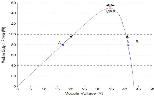
The Perturb & Observe algorithm states that when the operating voltage of the PV panel is perturbed by a small increment, if the resulting change in power P is positive, then we are going in the direction of MPP and we keep on perturb
bing in the same direction. If P is negative, we are going away from the direction of MPP and the sign of perturbation supplied has to be changed.
Therefore, we can move towards the MPP by providing a positive perturbation to the voltage. On the other hand, point B is on the right hand side of the MPP. When we give a positive perturbation, the value of P becomes negative, thus it is imperative to change the direction of perturbation to achieve MPP. The flowchart for the P&O algorithm is shown in Figure 2.
A.Main features of MPPT solar charge controller
•
In any applications which PV module is energy source, MPPT solar charge controlleris used to correct for detecting the variations in the current-voltage characteristics of solar celland shown by I-V curve.•
MPPT solar charge controlleris necessary for any solar power systems need to extract maximum power from PV module; it forces PV module to operate at voltage close to maximum power point to draw maximum available power.•
MPPT solar charge controllerallows users to use PV module with a higher voltage output than operating voltage ofbattery system. .
For example,if PV module has to be placed far away from charge controller and battery, its wire size must be very large to reduce voltage drop. With a MPPT solar charge controller, users can wire PV module for 24 or 48 V (depending on charge controller and PV modules) and bring power into 12 or 24 V battery system. This means it reduces the wire size needed while retaining full output of PV module.
•
MPPT solar charge controllerreduces complexity of system while output of system is high efficiency. Additionally, it can be applied to use with more energy sources. Since PV output power is used to control DC-DC converter directly.•
MPPT solar charge controllercan be applied to other renewable energy sources such as small water turbines,wind-power turbines, etc.
Simplified Model of The PV Panel
Many different models of the PV cell can be found in the literature. One of the most widely used is the single diode model, which, in many applications, represents a good compromise between accuracy and simplicity.
where V and I are the panel voltage and current, Iph is the photo current, Is is the reverse saturation current, and VT is the thermal voltage. Finally, Rs and Gsh are the series resistance and the shunt conductance, respectively. Often Gsh is supposed to be zero, because it does not produce relevant effects around MPP, where the PV module is supposed to operate [16], [17].
Fig4. Equivalent Electric Circuit Of The Proposed Model.
A good match with the actual V–I characteristic can be any way reached by opportunely tuning the thermal voltage and series resistance [16], [18]. On the contrary, Rs cannot be usually neglected because small variations may significantly affect the V –I curve around the MPP [16], [18]. The equation of the single diode model with zero-shunt conductance (Fig. 1) can be written as follows:
MPPT System
A.How Maximum Power Point Tracking works
Here is where the optimization, or maximum power point tracking comes in. Assume your battery is low, at 12 volts. A MPPT takes that 17.6 volts at 7.4 amps and converts it down, so that what the battery gets is now 10.8 amps at 12 volts. Now you still have almost 130 watts, and everyone is happy. Ideally, for 100% power conversion you would get around 11.3 amps at 11.5 volts, but you have to feed the battery a higher voltage to force the amps in. And this is a simplified explanation - in actual fact the output of the MPPT charge controller might vary continually to adjust for getting the maximum amps into the battery. A MPPT tracks the maximum power point, which is going to be different from the STC (Standard Test Conditions) rating under almost all situations. Under very cold conditions a 120 watt panel is actually capable of putting over 130+ watts because the power output goes up as panel temperature goes down - but if you don't have some way of tracking that power point, you are going to lose it. On the other hand under very hot conditions, the power drops - you lose power as the temperature goes up. That is why you get less gain in summer.
MPPT's are most effective under these conditions
Winter, and/or cloudy or hazy days - when the extra power is needed the most.
Cold weather - solar panels work better at cold temperatures, but without a MPPT you are losing most of that. Cold weather is most likely in winter - the time when sun hours are low and you need the power to recharge batteries the most.
Low battery charge - the lower the state of charge in your battery, the more current a MPPT puts into them - another time when the extra power is needed the most. You can have both of these conditions at the same time
.Long wire runs - If you are charging a 12 volt battery, and your panels are 100 feet away, the voltage drop and power loss can be considerable unless you use very large wire. That can be very expensive. But if you have four 12 volt panels wired in series for 48 volts, the power loss is much less, and the controller will convert that high voltage to 12 volts at the battery. That also means that if you have a high voltage panel setup feeding the controller, you can use much smaller wire.
Fig 7.voltage and power relation
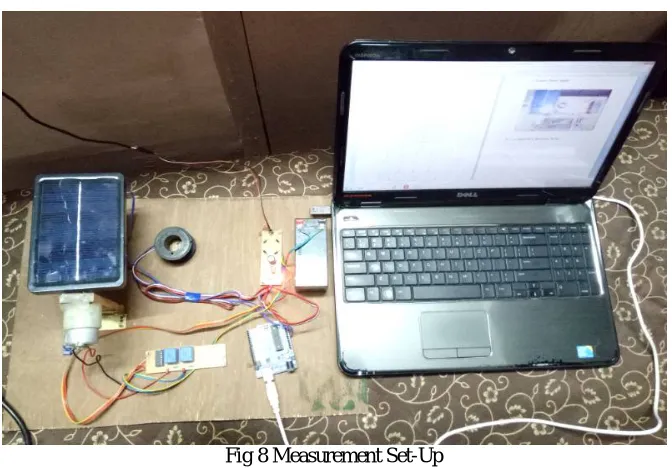
Measurement Set-Up
Fig 8 Measurement Set-Up
VI. RESULT
Fig.9-current-voltage characteristics
The Current – Voltage characteristic curve of a PV cell for certain irradiance at a fixed cell temperature is shown in fig.2. The current from a PV cell depends on the external voltage applied and the amount of sunlight on the cell. When The PV cell circuit is short, the current is at maximum and the voltage across the cell is zero. When the PV cell circuit is
Open, the voltage is at maximum and the current is zero.
The results shows that increase the light intensity will increase both voltage and current According to what has been discussed before in theory section, the temperature will have a direct effect on the characteristic of the PV module. Placing the desk lamp, which is generates heat, 3cm apart from the PV surface for period of time will causes to increase it temperature, especially when light intensity of the lamb is high or near to maximum. Therefore, the voltage is going to decrease remarkably, while the current is going to increase slightly.
Fig 10-power voltage characteristics
VII.CONCLUSION AND FUTURE WORK
Based on the obtained results we can conclude that the proposed solution for a solar tracking system offers several advantages concerning the movement command of the PV panel:
-An optimum cost/performance ratio, which is achieved via the simplicity of the adopted mechanical solution and the flexibility of the intelligent command strategy;
- A minimum of energy consumption, due to the fact that the panel movement is carried out only in justified cases, eliminating unnecessary consumption of energy, and due to the cutting of the power circuits supply between the movement periods of the PV panel;
- A maximisation of output energy produced by the PV panel, through an optimal positioning executed only for sufficient values of light signal intensity;
- A guarantee of the panel positioning starting from any initial position of the PV panel;
- The elimination of unnecessary movements, at too small intensities of the light signals or at too small differences between the signals received from the two LEDs; the possibility of extending this solution to an array of PV panels, connected to each other, with inter-connected operability by CAN protocol communication among the panels and managed by a central computation unit for monitoring and control;
The possibility of centralized monitoring and diagnosis of the system operation. Based on the obtained results we can affirm that proposed solution is effective and presents interesting advantages from the point of view of practical applicability to larger power PV structures
REFERENCES
[1] R. S.Lewis, "Antartic Research and Relevant of Science," in Bulletin of the Atomic Scientists, vol. 26, 1970, pp. 2.
[2] Y.-H. Chang and C.-Y. Chang, "A Maximum Power Point Tracking of PV System by Scaling Fuzzy Control," presented at International Multi Conference of Engineers and Computer Scientists, Hong Kong, 2010.
[3] S.Mekhilef, "Performance of grid connected inverter with maximum power point tracker and power factor control," International Journal of Power Electronics, vol. 1, pp. 49-62, 2008.
[4] M.E.Ahmad and S.Mekhilef, "Design and Implementation of a Multi Level Three-Phase Inverter with Less Switches and Low Output Voltage Distortation,"Journal of Power Electronics, vol. 9, pp. 594-604, 2009.
[5] S. Chin, J. Gadson, and K. Nordstrom, "Maximum Power Point Tracker," Tufts University Department of Electrical Engineering and Computer Science, 2003, pp. 1-66.
[6] R. Faranda and S. Leva, "Energy Comparison of MPPT techniques for PV Systems," WSES Transaction on Power Systems, vol. 3, pp.446-455, 2008.
[7]T.Markvart, “Solar Electricity”, John Wiley & Sons, 1994. [8]S.Roberts,”Solar Electricity”, Prentice Hall, 1991.
[9]C.R.sullivan and M.J Powers, “A High Efficiency Maximum Power Point Tracking for PhotovoltaicsArrays in a solar power Race vehicle, IEEE 1993, pp574 580.
[10]F.Harashima and H.Inaba, “Microprocessor controlled SIT Inverter for Solar Energy System”, IEEE Trans. On Industrial Electronics, vo.IE34, no.1, Feb. 1985, pp5055.
[11]G. Walker and P. C. Sernia, “Cascaded DC- DC converter connection of photovoltaic modules,” IEEE Trans.Power Electron., vol. 19, no. 4, pp. 1130-1139, Jul. 2004.
[12] T. Ikegami, T. Maezono, F. Nakanishi, Y. Yamagata, and K. Ebihara, “Estimation of equivalent circuit parameters of PV module and its application to optimal operation of PV system,” Solar Energy Mater. Solar Cells, vol. 67, nos. 1–4, pp. 389–395, Mar. 2001.
[13] W. Xiaolei, J. Huai-Zhen, Y. Liang, and Y. Pan, “A new method of MPPT
control based on the model of photovoltaic array,” in Proc. Power Energy Eng. Conf., Mar. 2011, pp. 1–3. CRISTALDI et al.: IMPROVED MB MPPT 71
[14] L. Cristaldi, M. Faifer, F. Ponci, and M. Rossi, “A simple photovoltaic panel model: Characterization procedure and evaluation of the role of environmental measurements,” IEEE Trans. Instrum. Meas., vol. 61, no. 10, pp. 2632–2641, Oct. 2012.
[15] G. Walker, “Evaluating MPPT converter topologies using a MATLAB PV model,” J. Electr. Electron. Eng., vol. 21, no. 1, pp. 49–56, 2001 [16] D. A. Adkins, “Novel method and system for monitoring CPV cell and module temperature,” in Proc. 35th IEEE PVSC, Jun. 2010, pp. 1660– 1665.