Available Online at www.ijcsmc.com
International Journal of Computer Science and Mobile Computing
A Monthly Journal of Computer Science and Information Technology
ISSN 2320–088X
IMPACT FACTOR: 6.199
IJCSMC, Vol. 8, Issue. 9, September 2019, pg.30 – 48
A New Approach for
Data Cryptography
Ziad Alqad
1; Majid Oraiqat
2; Hisham Almujafet
3; Salah Al-Saleh
4;
Hind Al Husban
4; Soubhi Al-Rimawi
41Department of Computer Engineering, Al Balqa Applied University, Amman, Jordan 2
Department of Communications Engineering, Al Balqa Applied University, Amman, Jordan 3
Department of Mechanical Engineering, Al Balqa Applied University, Amman, Jordan 4
Department of Financial, Administrative and Computer Sciences, Balqa'a Applied University / Zarqa University College
Abstract: Due to the large number of different computer applications transactions on the internet, cryptography is a vital key in ensuring the security of the transactions. Cryptography is an important way of achieving data confidentiality, data integrity, user authentication and non-repudiation.
In this paper we will introduce a new approach of message encryption-decryption, this approach will be implemented, and the experimental results will compared with the results of DES method of data cryptography.
The following features of the proposed approach will be proved:
- Simplicity.
- Efficiency.
- High security level.
- Flexibility
Keywords: Secret message, source color image, DES, encryption time, decryption time, security.
1- Introduction
1-2 DES
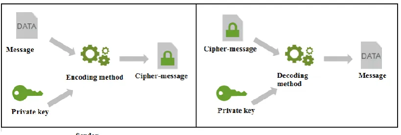
Data security [1], [2] is the process of protecting data from unauthorized access and data corruption throughout its lifecycle. Data security includes data encoding-decoding, tokenization, and key management practices( key selection and key generation) that protect data across all applications, networks communications and platforms [3], [4], [5].
Figure 1: Symmetric data encoding-decoding
- Dividing the data message into blocks with 64 bits long.
- Selecting a private key with fixed length (64 bits for DES method).
- Key generation to define subkeys.
- Initial permutation of blocks.
- Breakdown of the blocks into two parts left and right.
- Permutation and substitution steps repeated 16 rounds, applying logical and mathematical operations in each round using a defined feistel function and s-box.
- Re-joining of the left and right parts to form the decoded block of the message.
- Applying inverse procedures to get the encoded block.
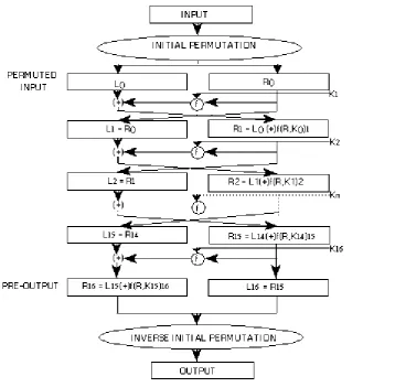
Figure 2: DES operations
To explain DES operations we will introduce a practical example.
Worked example:
Suppose we have a plaintext M which is equal:
85E813540F0AB405
First we divide this block into half left and half right:
Since the first entry in the table is "57", this means that the 57th bit of the original key K becomes the first bit of the permuted key K+. The 49th bit of the original key becomes the second bit of the permuted key. The 4th bit of the original key is the last bit of the permuted key. Note only 56 bits of the original key appear in the permuted key.
We get a 56 bits key as:
We split this key into 2 halves, where each half is 28 bits long:
With C0 and D0 selected, we can create sixteen blocks Cn and Dn, 1<=n<=16. Each pair of
blocks Cn and Dn is formed from the previous pair Cn-1 and Dn-1, respectively, for n = 1, 2... 16, using the
following schedule of "left shifts" of the previous block. To do a left shift, move each bit one place to the left, except for the first bit, which is cycled to the end of the block.
This means, for example, C3 and D3 are obtained from C2 and D2, respectively, by two left shifts,
and C16 and D16 are obtained from C15 and D15, respectively, by one left shift. In all cases, by a single left
We now form the keys Kn, for 1<=n<=16, by applying the following permutation table to each of the
concatenated pairs CnDn. Each pair has 56 bits, but PC-2 only uses 48 of these.
Therefore, the first bit of Kn is the 14th bit of CnDn, the second bit the 17th, and so on, ending with the
48th bit of Kn being the 32th bit of CnDn.
For the first key we have
Which, after we apply the permutation PC-2, becomes
Now we encode each 64-bit block of data.
There is an initial permutationIP of the 64 bits of the message data M. This rearranges the bits according to the following table, where the entries in the table show the new arrangement of the bits from their initial order. The 58th bit of M becomes the first bit of IP. The 50th bit of M becomes the second bit of IP. The 7th bit of M is the last bit of IP.
Applying the initial permutation to the block of text M, given previously, we get
Here the 58th bit of M is "1", which becomes the first bit of IP. The 50th bit of M is "1", which becomes the second bit of IP. The 7th bit of M is "0", which becomes the last bit of IP.
Next divide the permuted block IP into a left half L0 of 32 bits, and a right half R0 of 32 bits.
From IP, we get L0 and R0
We now proceed through 16 iterations, for 1<=n<=16, using a function f which operates on two blocks--a data block of 32 bits and a key Kn of 48 bits--to produce a block of 32 bits. Let + denote XOR addition, (bit-by-bit addition modulo 2). Then for n going from 1 to 16 we calculate
This results in a final block, for n = 16, of L16R16. In each iteration we take the right 32 bits of the
previous result and make them the left 32 bits of the current step. For the right 32 bits in the current step, we XOR the left 32 bits of the previous step with the calculation f.
For n = 1, we have
It remains to explain how the function f works. To calculate f, we first expand each block Rn-1 from 32
bits to 48 bits. This is done by using a selection table that repeats some of the bits in Rn-1. We'll call the
Let E be such that the 48 bits of its output, written as 8 blocks of 6 bits each, are obtained by selecting the bits in its inputs in order according to the following table:
Thus the first three bits of E (Rn-1) are the bits in positions 32, 1 and 2 of Rn-1 while the last 2 bits of E
(Rn-1) are the bits in positions 32 and 1.
We calculate E (R0) from R0 as follows:
(Note that each block of 4 original bits has been expanded to a block of 6 output bits.)
Next in the f calculation, we XOR the output E (Rn-1) with the key Kn:
For K1 , E (R0), we have
We have not yet finished calculating the function f . To this point we have expanded Rn-1 from 32 bits to
48 bits, using the selection table, and XORed the result with the key Kn . We now have 48 bits, or eight
groups of six bits. We now do something strange with each group of six bits: we use them as addresses in tables called "S boxes". Each group of six bits will give us an address in a different S box. Located at that address will be a 4 bit number. This 4 bit number will replace the original 6 bits. The net result is that the eight groups of 6 bits are transformed into eight groups of 4 bits (the 4-bit outputs from the S boxes) for 32 bits total.
Write the previous result, which is 48 bits, in the form:
Where each Bi is a group of six bits. We now calculate
To repeat, each of the functions S1, S2... S8, takes a 6-bit block as input and yields a 4-bit block as output. The table to determine S1 is shown and explained below:
If S1 is the function defined in this table and B is a block of 6 bits, then S1(B) is determined as follows:
The first and last bits of B represent in base 2 a number in the decimal range 0 to 3 (or binary 00 to 11). Let that number be i. The middle 4 bits of B represent in base 2 a number in the decimal range 0 to 15 (binary 0000 to 1111). Let that number be j. Look up in the table the number in the i-th row and j-th column. It is a number in the range 0 to 15 and is uniquely represented by a 4 bit block. That block is the output S1(B) of S1 for the input B. For example, for input block B = 011011 the first bit is "0" and the last
bit "1" giving 01 as the row. This is row 1. The middle four bits are "1101". This is the binary equivalent of decimal 13, so the column is column number 13. In row 1, column 13 appears 5. This determines the output; 5 is binary 0101, so that the output is 0101. Hence S1(011011) = 0101.
For the first round, we obtain as the output of the eight S boxes:
The final stage in the calculation of f is to do a permutation P of the S-box output to obtain the final value of f:
From the output of the eight S boxes:
We get
In the next round, we will have L2 = R1, which is the block we just calculated, and then we must
calculate R2 =L1 + f(R1, K2), and so on for 16 rounds. At the end of the sixteenth round we have the
blocks L16 and R16. We then reverse the order of the two blocks into the 64-bit block
R
16L
16And apply a final permutation IP-1 as defined by the following table:
That is, the output of the algorithm has bit 40 of the pre-output block as its first bit, bit 8 as its second bit, and so on, until bit 25 of the pre-output block is the last bit of the output.
If we process all 16 blocks using the method defined previously, we get, on the 16th round,
We reverse the order of these two blocks and apply the final permutation to
Which is in hexadecimal format:
This is the encrypted form of M = 0123456789ABCDEF: namely, C = 85E813540F0AB405.
Decryption is simply the inverse of encryption, following the same steps as above, but reversing the order in which the subkeys are applied.
1-2 Digital color images
Digital color image is an important type of data used over the internet, every color image is consisted of three channels [12], [13], the first channel is the red color, the second is the green color, while the third one is the blue color, mixing these colors to gather forms the pixel color [14], [15].
Digital color image in processing phase can be considered as 3D matrix, the first dimension is reserved for the red color, the second dimension is reserved for the green color, and the third one is reserved for the blue color[16], [17].
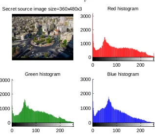
Each color image can be studied using its histogram which is an array that contains the repetitions of each color value (0 to 255), one histogram can calculated for each color [16], [17] as shown in figure 3.
Figure 3: Color image and histograms
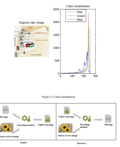
If the color image is equalized [18] then the colors values are normally distributed, and the histogram will contains all the values within the range 0 to 255 as shown in figure 4, thus the histogram of the color image can cover all the characters in ASCII table, which means that the color image can be considered as a bank of data which can contain any message with any combination of letters, this fact will be considered in the proposed novel approach of message encryption-decryption, and here instead of using a private key we can use a color image as a source which supply us with the needed codes for any given secret massage as shown in figure 5.
Image holding 3 messages
0 100 200
0 200 400 600
Red histogram
0 100 200
0 200 400 600
Green histogram
0 100 200
Figure 4: Colors distribution.
Figure 5: New approach of message encryption-decryption.
2- The Proposed Approach
Based on the normal color distribution in the image histogram we can use the pixel position (row, column and color channel number) to decode any character from ASCII table, these codes will be fixed for the selected source image and the selected secret message , to apply the coding we have to perform the following steps:
1) Select the source secret color image 2) Equalize the image if necessary. 3) Get the secret message.
4) Initialize the code matrix.
5) For each character in the secret message do the following: a) Get the decimal value of the character.
b) Find the first appearance of the decimal value in the image. c) Retrieve the position values.
Original color image
0 100 200 300
0 500 1000 1500 2000 2500
Colors dustribution
d) Add the retrieved position values to the code matrix. 6) Save the code matrix (the encrypted message).
The decryption phase can be implemented applying the following steps:
1) Get the source secret image (must be the same image used in the encryption phase). 2) Get the encrypted message.
3) Initialize the decrypted massage.
4) For each row in the encrypted message do the following.
a) Get the row, column and color channel.
b) Use the retrieved position to get the character value from the image. c) Concatenate the obtained value to decrypted message.
5) Change the decimal values of the obtained message to characters to get the original message.
Using this approach we have to pay attention on the following facts:
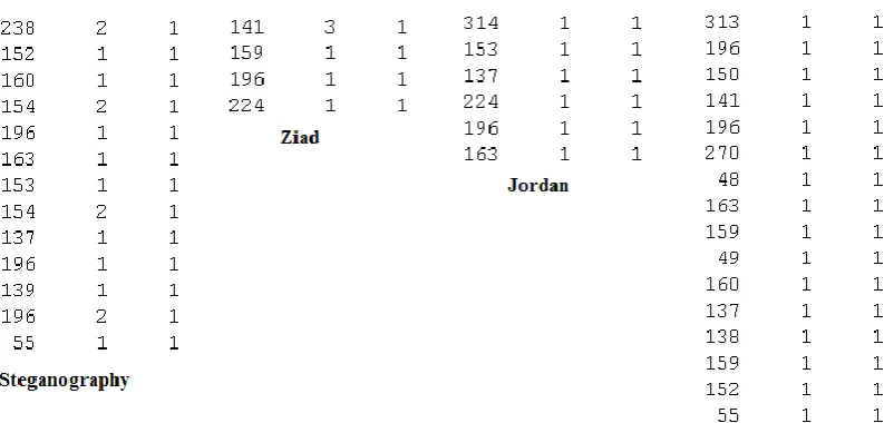
- One color image can be used as source image to get the encrypted form of any message with any combination of characters, as shown in figure 6:
Figure 6: Messages encryption using the same source image.
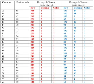
- Every image encodes the message depending on its own data, so various images generate various codes for the same character as shown in table 1.
- One image can be used to encode a message with unlimited size (the message size may be even bigger than the image size).
- The correct encrypted message can be obtained only by using the desired source image. This image is only known by the sender and receiver.
- The proposed approach provides a high level of security, because it is very difficult to guess the source image. Here the number of combination used for guessing equal ( r:number of rows, c:number of columns, 3 : number of color in the source image), if the image with size 400x300x3 then the number of combinations is a very huge number and it is equal to:
9.8332167945635864126735468519358e+1692 (very big number!!).
- The proposed approach is very efficient and will show this in the implementation part. Table 1: Different codes using different images
Character Decimal value Decrypted Character using image 6
Decrypted Character using image 1 Row Column Color Row Column Color
A 65 308 1 1 133 14 1
B 66 313 1 1 102 18 1
C 67 205 3 1 133 7 1
D 68 226 3 1 63 6 1
E 68 306 1 1 132 14 1
F 70 300 1 1 92 6 1
G 71 197 2 1 61 35 1
H 72 231 2 1 132 13 1
I 73 220 2 1 63 7 1
J 74 314 1 1 136 8 1
K 75 197 1 1 136 7 1
L 76 207 2 1 89 35 1
M 77 228 2 1 72 4 1
N 78 228 3 1 132 8 1
O 79 227 1 1 87 3 1
P 80 213 2 1 101 23 1
Q 81 240 1 1 145 11 1
R 82 213 1 1 72 3 1
S 83 238 2 1 97 5 1
T 84 228 1 1 97 3 1
U 85 220 1 1 148 8 1
V 86 222 3 1 142 14 1
W 87 198 1 1 133 13 1
X 88 225 1 1 94 3 1
Y 89 210 1 1 77 4 1
Z 90 141 3 1 60 5 1
3- Implementation and Experimental Results
For comparisons purposes we select DES method of data encryption-decryption, because it is one of the simplest method among the other used symmetric methods of data cryptography.
DES method was implemented using matlab, figure 7 shows the GUI of the program, while table 2 shows the efficiency parameters measured for this method using various messages with a private key=931955.
Table 2: Efficiency parameters for DES method
Message length Encryption time(seconds) Decryption time(seconds)
11 0.1480 0.0600
26 0.1800 0.1000
35 0.2190 0.1190
48 0.2390 0.1530
60 0.3200 0.1680
64 0.3210 0.1690
72 0.3670 0.1860
80 0.4650 0.1870
85 0.5190 0.2040
90 0.5930 0.2090
95 0.6170 0.2127
100 0.6540 0.2290
Figure 7: GUI of DES method
Here we have to notice that the private key long does not affect the measures times.
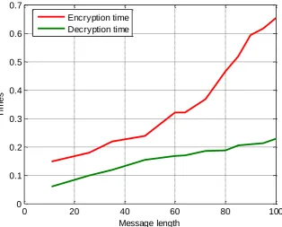
Here we can see that both the encryption and decryption times grow with message length growing as shown in figure 8.
Figure 8: Encryption-decryption times
The new approach was also implemented using matlab; figure 9 shows the GUI of this implementation
0 20 40 60 80 100
0 0.1 0.2 0.3 0.4 0.5 0.6 0.7
Message length
T
im
e
s
Figure 9: New approach GUI
The image shown in figure 10 was selected as a source image and the same experiment used in DES was repeated using the new approach, table 3 show the experimental results of the implementation.
F
Figure 10: Source color image Secret source image size=360x480x3
0 100 200
0 1000 2000 3000
Red histogram
0 100 200
0 1000 2000 3000
Green histogram
0 100 200
0 1000 2000 3000
Table 3: Efficiency parameters for the new approach
Message length Encryption time(seconds) Decryption time(seconds)
11 0.008000 0.000001
26 0.016000 0.000001
35 0.020000 0.001000
48 0.027000 0.001300
60 0.032000 0.001400
64 0.035000 0.001400
72 0.037000 0.001500
80 0.041000 0.001700
85 0.046000 0.001750
90 0.048000 0.001800
95 0.061000 0.001830
100 0.068000 0.001880
Average :63.8333 0.0366 0.0013
Speed up of the new approach 0.3868/0.0366=10.5683 times 0.1664/0.0013=128 times
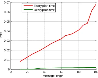
Figure 11 illustrates the relationship between encryption, decryption times and message length.
Figure 11: Relationship between encryption, decryption times and message length
From the obtained results we can see that in average the proposed approach is faster in 10.5683 times in encryption phase comparing with DES method, and faster in 128 times in decryption phase comparing with DES method
Conclusions
A new approach of secret messages encryption-decryption was proposed, tested and implemented; the obtained experimental results showed and proved the following facts:
- The proposed approach can be considered as a symmetric method of data cryptography. - The same source color image can be used to encrypt-decrypt various messages.
0 20 40 60 80 100
- The message size to be encrypted is unlimited and it may exceed the image size. - The encryption process does not depend on the message contents.
- The security level is very high, because it is very difficult to guess the source image.
- The propose approach is very simple and does not require any arithmetic and logical operations, it also does not require any extra data structure such S-boxes.
- The propose approach provides a high efficiency comparing with DES method.
References
[1] Ziad A. Alqadi, Majed O. Al-Dwairi, Amjad A. Abu Jazar and Rushdi Abu Zneit, Optimized True-RGB color Image Processing, World Applied Sciences Journal 8 (10): 1175-1182, ISSN 1818-4952, 2010.
[2] A. A. Moustafa, Z. A. Alqadi, Color Image Reconstruction Using A New R'G'I Model, journal of Computer Science, Vol.5, No. 4, pp. 250-254, 2009.
[3] Jamil Al Azzeh, Hussein Alhatamleh, Ziad A. Alqadi, Mohammad Khalil Abuzalata, Creating a Color Map to be used to Convert a Gray Image to Color Image; International Journal of Computer Applications , November 2016,Volume 153,Issue 2.
[4] Jamil Al-Azzeh, Ziad Alqadi, Mohammed Abuzalata, Performance Analysis of Artificial Neural Networks used for Color Image Recognition and Retrieving, International Journal of Computer Science and Mobile Computing,2019,Volume 8 Issue 2.
[5] Jamil AL-Azzeh, Bilal Zahran, Ziad Alqadi, Belal Ayyoub and Mazen Abu-Zaher: A Novel Zero-Error Method to Create a Secret Tag for an Image; Journal of Theoretical and Applied Information Technology 15th July 2018. [6] Jamil AL-Azzeh, Bilal Zahran and Ziad Alqadi: Salt and Pepper Noise: Effects and Removal, International Journal on Informatics Visualization July 2018, Volume 2 Issue 4.
[7] Musbah J. Aqel , Ziad A. Alqadi, Ibraheim M. El Emary ,Analysis of Stream Cipher Security Algorithm, Journal of Information and Computing Science Vol. 2, No. 4, 2007, pp. 288-298.
[8] Belal Ayyoub, Ashraf Abu-Ein, Ziad Alqadi, Suggested Method to Create Color Image Features Victor, Journal of Engineering and Applied Sciences, 2019, Volume14, Issue7.
[9] K Matrouk, A Al-Hasanat, H Alasha'ary, Z. Al-Qadi,H Al-Shalabi, Speech fingerprint to identify isolated word person, World Applied Sciences Journal, Vol. 31, No. 10, pp. 1767-1771, 2014.
[10] Mohammed Abuzalata, Ziad Alqadi; Jamil Al-Azzeh; Qazem Jaber, Modified Inverse LSB Method for Highly
Secure Message Hiding, IJCSMC, Vol. 8, Issue. 2, February 2019, pg.93 – 103
[11] Mutaz Rasmi Abu Sara Rashad J. Rasras, Ziad A. AlQadi, Engineering, A Methodology Based on Steganography and Cryptography to Protect Highly Secure Messages Technology & Applied Science Research, Vol.9 Issue 1, Pages 3681-3684, 2019.
[12] Ziad Alqadi, Bilal Zahran, Qazem Jaber, Belal Ayyoub, Jamil Al-Azzeh, Ahmad Sharadqh, proposed Implementation Method to Improve LSB Efficiency, International Journal of Computer Science and Mobile Computing, Vol.8 Issue.3, March-2019, pg. 306-319.
[13] Deepak Garg, Gourav Sharma, Applications of Steganography in Information Hiding, international Journal of Advanced Research in Education & Technology (IJARET) 12 Vol. 3, Issue 1 (Jan. - Mar. 2016).
[14] J. Al-Azzeh, B. Zahran, Z. Alqadi, B. Ayyoub, M. Abu-Zaher, “A Novel zero-error method to create a secret tag for an image”, Journal of Theoretical and Applied Information Technology, Vol . 96. No. 13, pp. 4081-4091, 2018. [15] Prof. Ziad A.A. Alqadi, Prof. Mohammed K. Abu Zalata, Ghazi M. Qaryouti, Comparative Analysis of Color Image Steganography, JCSMC, Vol.5, Issue. 11, November 2016, pg.37–43.
*16+ M. Jose, “Hiding Image in Image Using LSB Insertion Method with Improved Security and Quality”, International Journal of Science and Research, Vol. 3, No. 9, pp. 2281-2284, 2014.
[17] Ziad Alqadi; Bilal Zahran; Qazem Jaber; Belal Ayyoub; Jamil Al-Azzeh, Enhancing the Capacity of LSB Method by Introducing LSB2Z Method; International Journal of Computer Science and Mobile Computing,2019,Volume 8 Issue 3.
*18+ Naseem Asad, Ismail Shayeb, “A Modification of Least Significant Digit (LSD) Digital Watermark Technique”, International Journal of Computer Applications
Volume 179 No.32, April 2018
[19+ Jamil Al Azzeh, Ziad Alqadi Qazem, M Jabber;”Statistical Analysis of Methods Used to Enhanced Color
Image”; XX International Scientific and Technical Conference;2016.
[20] Mazen Abuzaher Jamil Al-Azzeh, :JPEG Based Compression Algorithm”; International Journal of
Engineering and Applied Sciences, 2017,Volume 4 Issue 4.
[21] Jamil Al-Azzeh, Ziad Alqadi, Qazem Jaber; “A Simple, Accurate and Highly Secure Method to Encrypt-Decrypt