Available Online at www.ijcsmc.com
International Journal of Computer Science and Mobile Computing
A Monthly Journal of Computer Science and Information Technology
ISSN 2320–088X
IJCSMC, Vol. 5, Issue. 1, January 2016, pg.202 – 218
Indoor Way Finder Navigation
System Using Smartphone
Hamid M. Ali
1, Zahraa T. Noori
21Computer Engineering Dept.
,
Baghdad University, Iraq 2M.Sc. Student
,
Computer Engineering Dept.,
Baghdad University, Iraq1
[email protected], 2 [email protected]
Abstract --- Indoor way finding has recently gained high interest as one of the potential smartphone applications which helps people to find their destination especially in the big complicated buildings. Outdoor navigation systems use GPS to guide the users to their destination. However, in indoor navigation, the GPS is not effective and accurate solution due to signal blocking inside the buildings. Many indoor navigation systems use various infrastructures; such as Wi-Fi fingerprint, smartphone sensors only, NFC or extra hardware to construct the system. Also, most of the indoor navigation systems present, at user smartphone, the real floor plan for navigation purposes. Actually, users are not familiar and cannot interact visually with such plan; also extra time is required for processing and scaling the real map on the smartphone screen in conjunction with user moving steps. In this work, an indoor way finder navigation system using building existing Wi-Fi WLAN infrastructure with smartphone accelerometer sensor is constructed. Also, instead of using real building map, the proposed system suggested and implemented an idea to mimic real building map that reflects and supports augmented reality of the building, by displaying images of real user location path while navigating to the destination. It also provides a friendly and easy user interface by displaying navigation information as a real environment images associated with directional arrow, speech and texts during the navigation process to show the route to the desired location inside the building.
I. Introduction
Indoor navigation is becoming an essential requirement of our daily life due to the complexity of the building. There is a great need for a simple indoor way finding solution for smartphone helping people to find their way in the buildings. GPS is the most commonly used technique for outdoor localization, but unfortunately; obtaining accurate indoor localization results by using GPS is rarely possible. Many approaches and alternative techniques have been suggested and built indoor navigation system[1].
In [2] an indoor navigation system using Wi-Fi and smartphone sensors, accelerometer and magnetometer sensors, is presented. This system does not reflect the augmented reality of the whole path in the building since the user is required to take a picture for the initial location to enable the system to add the direction text of the shortest path on this picture. Also it is not guidance system as the directions of the shortest path are displayed to the user all at once. In [3] an indoor navigation system is presented by using Near Field Communication (NFC). This system needs the user to initialize the system by touching the smartphone to an NFC tag before entering the building to load the building map information from the server. Also the user needs to touch the smartphone to the NFC tags which are spread over the building to locate the user location and then get the next text direction to the next NFC tag. This system is inflexible to use since the user needs to search for the tag and scan it manually to get the location information and direction to the next tag. It is little difficult when user is moving fast. [4] Presents indoor navigation solution by using Pedestrian Dead Reckoning (PDR) based on smartphone magnetometer, gyroscope and accelerometer sensors with a developed map matching algorithm. Map matching algorithm fuses the measurements of the user position and direction by PDR to projecting it onto the nearest passageway. It needs for the physical map of the building; this can create a burden for the user in the large buildings which consist of number of floors. Also the distance between the real location and the estimated location is relatively high which decreases the all system performance. In [5] indoor navigation system using dead reckoning (DR) and Wi-Fi signal strength fingerprinting is presented. This system uses a robot for collecting Wi-Fi calibration data to generate a radio map in database. It comprises three core components: effective localization, map representation and route planning, and plan recognition. This system uses real building map to display a visual representation of the navigation process to the user. The using of robot leads to increase the complexity and the cost in the implementation of the system. Also the system is not able to converge to the final location with a higher degree of certainty because of some points are laid outside the boundaries of the created robot map also the magnetometer is effected by the magnetic drift interference in the environment. [6] Presents indoor navigation system by using Bluetooth technique. The smartphone scans the nearby Bluetooth access points and sends the results to the server. The server finds user location and shortest path to the destination, then this information are shown on the real floor map. This system needs additional requirements due to installing Bluetooth devices in the building;also it needs floor map of the building.
The proposed system design relies on Wi-Fi Access Points (APs), which are deployed in the most building nowadays, and the smartphone accelerometer sensor to implement the system. The system mechanism consists of two phases: the training phase and the navigation phase.
II. Training Phase
The training phase is performed by the system’s administrator. Fig1 shows the main components used and created during the training phase.
Fig 1 Training Phase Components
The smartphone of the system’s administrator is loaded with a utility that is responsible for performing the following functions:
1. Initially, the system administrator walks through the whole building and detects all the APs that belong to the building and stores the MACs of them in a temporary array inside the smartphone. In this process, the administrator excludes all the APs that belong to the neighbor buildings.
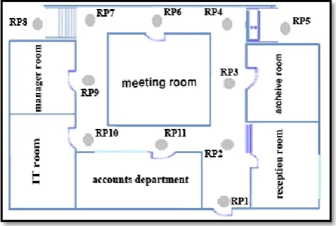
2. At each corridor of the floor building a number of locations, called reference points (RPs), are used for the purpose of identifying and constructing floor path. Also each RP should be 2.5m apart from each other. Fig 2 shows the distribution of the RPs in a building floor .
3. One of the main functions of the training phase is to create a Wi-Fi fingerprint for each RP in the building. At each RP, the administrator detects the RSSs of all the APs in the building. Hence each RP is identified by the different AP RSS values detected at that RP. Thus, at each RP a vector of all detected APs (AP RSS values and their MAC addresses), together with location name of the RP, are sent and stored in the building database server to be used in the navigation phase.
4. Also at each RP, the administrator, records the direction paths between current RP and the neighbour RPs and save them in two dimension matrix called “Direction Path Matrix” (DPM)
which is explained later in this section. The DPM is sent and stored in the database server, to be used in the navigation phase.
5. The administrator takes an image of the surrounding area at each RP to be sent and stored at the server together with RP fingerprint explained in step 3 above. The purpose of the image is to create a real environment of the path inside the building to be displayed at the user smartphone when the user arrives at certain RP in the navigation phase.
A. The Idea of the Direction Path Matrix
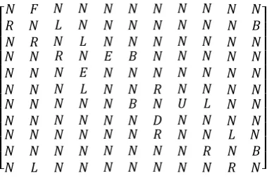
As explained in section II, the corridors of the floor building are covered with RPs for the purpose of partitioning the building into locations to be used for path determination in the navigation phase. To facilitate the process of anticipating the path between source and destination, the DPM constructed in the training phase, is used in the process of finding the directions between each RP during the navigation activity. The DPM is n x n two dimensional matrix where n is the number of RPs in the building. This matrix is filled by the system administrator with items: L, N, R, B, U, D, E and F. For example, consider the simple floorplan shown in Fig 2 which contains 11 RPs then DPM can be represented as shown in Fig 3.
[
] Fig 3 Direction Path Matrix
Where
DPM(x,y): x is the row , y is the column.
R in DPM(x,y) entry represents the direction from RPx to RPy is right.
L in DPM(x,y) entry represents the direction from RPx to RPy is left .
F in DPM(x,y) entry represents the direction from RPx to RPy is front.
N in DPM(x,y) entry represents there is no path between RPx and RPy.
B in DPM(x,y) entry represents the RPx is behind RPy.
D in DPM(x,y) entry represent that there is a stair between RPx and RPy and the user should down the stairs to reach RPy.
E in DPM(x,y) entry represent that there is an elevator between RPx and RPy and the user should take it to reach RPy.
B. Directions Setting
The directions between each two adjacent RPs are set in the training phase. The administrator walks through all RPs, facing each RP, and fills the “DPM” of each RP according to an existing direction path between the current RP and the adjacent RPs. For example, when the admin approaches and faces RP2, as shown in Fig 2, the DPM (2,1) is filled with “R” item as long as the admin is facing RP2 and RP1 is at his right, the DPM (2,3) is filled with “L” item as long as the admin is facing RP2 and RP3 is at his left, the DPM (2,11) is filled with “B” item as RP11 is behind RP2. DPM (2,2) is filled by the system with “N” item, then, as long as, there is no connection between RP2 and RP4, RP5, RP6, RP7, RP8, RP9 and RP10, the DPM (2,4), DPM (2,5), DPM (2,6), DPM (2,7), DPM (2,8) , DPM (2,9), and DPM (2,10) are filled by the system with“ N” item.
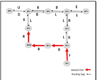
C. Building Map
Usually in indoor navigation system the user smartphone should be presented with real floorplan map of the building. Actually this approach has inconvenient features from the user point of view as most people are not familiar with building floorplan maps. Also, from the implementation point of view, extra time is required for processing and scaling the real map on the smartphone screen in conjunction with user moving steps.
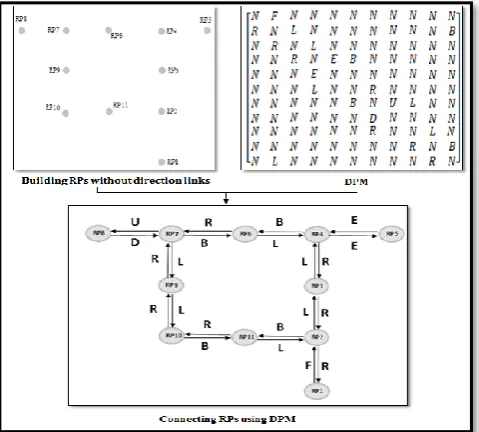
The proposed system exploited the use of deployed RPs in the building and the directions setting, explained in section II-B, to create the illusion of the real floorplan map as shown in Fig 4. The idea is to mimic the real map by having the administrator facing each RP and taking the image of the RP location to be stored in the server, during the training phase. These images are displayed, at the user smartphone, while reaching at each RP during the navigation phase. This approach makes the system flexible to be applied in any building as long as the burden of presenting and processing the real map is not required.
III
. Navigation Phase
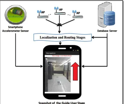
This is the application part of the system installed on the user smartphone which is used to provide the user with shortest path to the destination. Fig 5 shows the main components used in the Navigation phase. When this application runs on the user smartphone, it connects with database server and provides the user smartphone with all necessary data which are stored during the training phase to enable the smartphone to locate, show the route, direct and guide the user to the destination. This phase consists of three stages:
a. Localization Stage.
b. Shortest Path and Direction Stage.
c. Guide User Stage.
The first stage, Localization stage, is used to find user's current location inside the building. The second stage, Shortest Path and Direction Stage, is used to calculate the shortest path and set the correct direction from the user current location to the required destination. The third stage, Guide User Stage, is used to guide the user inside the building from the user source location along the shortest path route until reaching the destination.
A. Localization Stage
Localization stage adopted Wi-Fi fingerprint mechanism based on Euclidean equation to find the nearest RP to the user current location. During the localization stage, Wi-Fi RSS values of several APs are detected by user smartphone to determine user current location. A similarity measure between current location values and training phase values is calculated using Equation (1). A small D indicates a high similarity or nearest RP.
=√∑ ………. (1)
Where:
: is RSS value of APi in training phase. : is RSS value of APi in localization stage.
n: is number of detected APs in localization stage.
D:is the signal difference (Euclidean distance)
Variations of Wi-Fi signal strength in time and space make accurate indoor localization is not easy task to achieve. A number of factors affect the Wi-Fi RSS; these factors include Line of Site (LoS) or Non-Line of Site (NLoS) conditions and other considerations such as the presence of moving people and furniture. Hence, the location determination based on Wi-Fi fingerprint is affected by the above mentioned factors. To reduce the variation effect of Wi-Fi signal and to increase the accuracy of the system, the localization stage in this paper integrated the two mechanisms presented in [7] and [8] respectively. The two mechanisms and their integration are tested in a bank building that consists of 4 floors and contains 10 APs. In this test 53 RPs are assigned and tested in the whole building corridors. Fig 6 through Fig 8 shows the localization accuracy test represented in terms of 0RP shift which indicates exact estimated location, while 1RP shift, 2RP shift, 3RP shift and 4 RP shift indicate 1, 2, 3 and 4 RP shifts, respectively, in the estimated location. Floor shift indicates that the estimated location is shifted one floor or more.
In [7], at each RP and for four directions: north, south, west and east, the average of 20 RSSs (5 in each of 4 directions) values are collected for every detected AP producing a mean vector for each RP to be sent and stored at the database server. Fig 6 shows the accuracy, for this approach, of a practical test conducted at the bank building
Fig 6 Localization Accuracy in the Bank of [7]
0RP Shift 1RP Shift 2RP Shift 3RP shift 4RP Shift floors
Shift
Accuracy 31.21% 29.75% 19.22% 8.13% 2.09% 9.59%
0% 10% 20% 30% 40% 50% 60% 70% 80% 90% 100%
In [8], equal number of matching AP at each RP is maintained to increase the accuracy of the Euclidian equation. So if no signal is received from an AP in training phase, this AP is labelled as -99dBm. Also to reduce the error in accuracy that occur between fingerprint RPs and the user's location point in finding nearest RP, a filter, Equation (2), is added to prevent the large difference in any term of Euclidian equation.
Let =
If | | >= threshold = threshold … (2)
If | | < threshold no change.
Fig 7 shows the accuracy, for this approach, of a practical test conducted in the bank building.
Fig 7 Localization Accuracy in the Bank of [8]
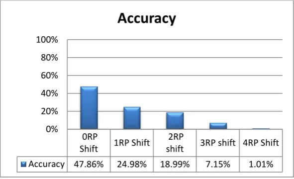
In this work the two mechanisms of [7] and [8] have been combined together to increase the localization process accuracy as shown in Fig 8 for the same practical test.
Fig 8Localization Accuracy in the Bank of the Adopted Mechanism 0RP
Shift
1RP Shift
2RP
shift 3RP shift
4RP Shift
Accuracy 47.86% 24.98% 18.99% 7.15% 1.01%
0% 20% 40% 60% 80% 100%
Accuracy
0RP
Shift 1RP Shift
2RP
shift 3RP shift 4RP Shift
Accuracy 47.86% 24.98% 18.99% 7.15% 1.01%
0% 20% 40% 60% 80% 100%
B. Shortest Path and Direction Stage
In this stage the shortest path, between user's location and her/his destination is calculated by using Dijkstra's Algorithm[9]. The results from this stage are two vectors, 'Path Vector' which contains the minimum number of RP locations that the user should pass through to reach the destination and 'Direction Vector' which contains the direction between two contiguous RPs inside the Path Vector as fixed in the DPM during the training phase.
For example, in the simple floor plan shown in Fig 2, suppose that the user started the application at RP1 location and the destination is RP9 location, then referring to Fig 4 for finding the shortest path between RP1 and PR9, the two vectors, Path Vector and Direction Vector are generated as follows:
Path Vector = [ ] Direction Vector = [ ]
Fig 9 shows the use of Path Vector and Direction Vector to construct a directed shortest path from RP1 to RP9.
Fig 9 Shortest Path between RP1 and RP9
1- Each item in the Direction Vector is modified by taking the corresponding RP in the Path Vector.
2- Consult the DPM to extract the direction links to the previous and next RPs, in the path vector, respectively.
3- Access the Navigation Direction Matrix with links obtained from step 2 above; the previous and next link directions represent row and column in the Navigation Direction Matrix, respectively.
4- Only the direction of the source RP is taken from the DPM with no change as it is the first RP in the Path Vector with no Previous RP. In fact, in this work the system instructs the user to face only the first (source) RP image. Then after user confirmation that she/he is facing the image, the system starts the navigation journey. The reason behind that is to obtain the user initial direction, as specified in the training phase, then the rest of the path directions are extracted from the DPM and Navigation Direction Matrix, as explained above.
Then
the Direction Vector is modified using the Navigation Direction Matrix to be: - [F L F R ].
Then the Path and Direction Vectors are sent to the third stage of the proposed system, Guide User Stage, section III-C, to visually and interactively show the route to the user.Next
Previous
L
R
B
F
E
D
U
L
-
F
R
L
E
D
U
R
F
-
L
R
E
D
U
B
L
R
-
F
E
D
U
F
R
L
F
-
-
-
-
E
R
L
F
-
-
-
-
D
R
L
F
-
-
-
U
U
R
L
F
-
-
D
-
Fig 10 Navigation Direction Matrix
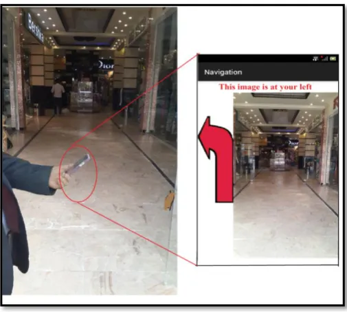
C. Guide User Stag
Fig 11 Snapshot of the Guide User Stage
1) Flow of the Guide User Stage: The following operations are performed during the Guide User
Stage mechanism:
a. Taking the Path Vector and Direction Vector, generated in the Shortest Path and Direction stage:
b. Once the image of the RP1 is displayed to the user, the system starts checking the smartphone accelerometer sensor to detect user steps which is accomplished by taking the current X, Y, Z-axes coordinate of the accelerometer sensor and find the total acceleration using equation 4 [10].
G=√ … (4)
The value of G is then compared with the threshold of detecting new steps: G >= threshold new step is detected
G < threshold no new step
c. On each detected step, the system repeats the localization stage to determine user new location. The system compares the new location RP with the next RP of the Path Vector to make sure that the user is in the correct route. If the user has moved several steps and it is found near the next RP of the Path Vector, a new image associated with this RP location is displayed on the user smartphone screen. Finding the user not proximate to next RP of the Path vector, necessities finding new shortest path again by “Finding New Route Procedure”, explained in details in this section, then the system instruct and guide the user to her/his destination.
d. Step cabove is repeated until the last RP in the Path Vector, the destination RP, is reached.
new Path and Direction Vectors. As the distance from RP to the next RP is 2.5m, the system is made to find the approximate distance of the user movement from certain RP to the next RP in her/his path to the destination. Intuitively, the length of the human step is varying from one to one. [11] and [12] have made a survey study and found that 0.762m represents the average step length of human. Hence the distance of human walking is:
Distance = Total Steps * 0.762
Actually the system is made to find new route when a number of wrong steps exceed 4 steps, as threshold, are moved by the user, then the system starts “Finding New Route Procedure” which implies find new user location (source RP), calculating new shortest path to produce new Path and Direction Vectors. Then the system instructs and directs the user to the destination based on the new generated Path Vector. The 4 steps threshold is chosen to be adequate measure for the user to pass from current RP to the next RP in the Path Vector.
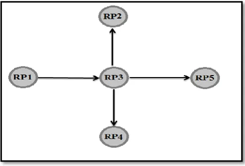
3) Minimizing the Effect of the Localization Error: Actually, the system enters the Find New Route Procedure in two cases as mentioned previously; first, when the user moves in a wrong direction, second, when the localization stage gives a wrong position. In order to overcome some of the localization errors and improve the system performance, the system does not enter the Find New Route Procedure when the localization process finds the RP that is neighbor to the next expected RP in the path vector. For example suppose that there are five RPs: RP1, RP2, RP3, RP4 and RP5, as shown in Fig 12; and the shortest path vector is from RP1 to RP5 is: RP1 RP3 RP5
Fig 12 Five Connected RPs
Suppose, after locating RP1, the system currently looking for RP3, but due to the 1 RP shift of the localization process, the system located RP1, RP2, RP4 or RP5. In this case, the system is made to recover from 1 RP shift, as long as the number of steps from RP1 to RP3 is not exhausted. The system then concludes that RP3 is located as the next RP after RP1 in the Path Vector. The idea behind that; the user is not standing steadily at certain RP, actually the user is moving proximate to the RPs in the path to his destination.
IV. Performance Results and Evaluation
This section demonstrates and illustrates the practical performance results that are obtained from applying the proposed system in real environment; the bank building. The proposed indoor navigation is evaluated by performing 6 tests each of which with different source and destination locations. Hence, 6 different routes with 1 shortest path vector for each route is produced with different number of locations, RPs, to be traversed. Tables 1 through Table 6 show the performance results of the proposed system mechanism for test 1 to test 6, respectively. Each route, presented in the tables, is analyzed separately to reflect each state of the theoretical model. Each column label in the table is explained as follows:
Path Vector: represents the contiguous RPs that has to be traversed by the user from the first RP,
the source location, to the last RP, the destination location.
Location Name: represents the well-known place corresponding to each RP mentioned in the Path
Vector in the building, from the source to the destination that has to be traversed by the user.
Estimated location: represents the current user location determined by the localization process; √
means the user is proximate to the corresponding RP in the same row of the table, X means the user is not proximate to the corresponding RP in the same row of the table.
Neighbour RP: represents the current user location, determined by the localization process, is
proximate to the neighbour RP of the expected RP in the Path Vector; √ means the user is proximate to the one of the neighbour RPs of the RP in the same row of the table, X means the user is not proximate to any neighbour of the RP in the same row of the table.
New Route: √ indicates that the user current location is neither proximate to the corresponding RP
in the Path Vector nor proximate to its neighbours. In this case, the system finds new route for the user.
A. Test 1
This test reveals that this navigation test has achieved a successful navigation performance. After locating RP1 correctly and while the user is moving toward RP2, the system expected to find RP2 as indicated in the Path Vector. But instead, as shown in the table, the system has located the user proximate to the one of the RP2 neighbors as indicated by X in the estimated location column and √ in the Neighbor RP column. Hence, the proposed system considers this case as 1 RP shift of the localization process accuracy. It then concludes that the user is proximate to RP2 as long as the number of steps threshold has not been exhausted from RP1 to RP2. After locating RP3, RP4 and RP5 correctly, the same discussion of locating RP2 is applied when locating RP6. Eventually, the destination RP7 is located correctly. This test has been proved by the images, animated directional arrow and speech presented by the smartphone during the test.
Table 1 Test 1 of the Proposed System Mechanism
B. Test 2
Test 2 achieved the same performance results of test 1; also the same performance analysis discussed for test 1 is applied for this test.
Table 2 Test 2 of the Proposed System Mechanism
Test 2 New Route Neighbor RP Estimated Location Location Name Path Vector Sequence - - √ Branch manager RP7 1 - - √ Assistant manager RP6 2 - - √ Saving account RP5 3 - √ X Current account RP4 4 - - √ Exchange Dept. RP3 5 - - √ Waiting room RP2 6 - - √ Selling Cars RP8 7 - √ X Teller 1 RP9 8 - -√ Teller 2 RP10 9
C. Test 3
This test is similar to Tests 1 and 2, in its cases, with one exception that after locating RP40 correctly and while the user is moving toward RP41, as indicated in the path vector, neither RP41 nor any of its neighbors are detected when the number of steps threshold has been exhausted from RP40 to RP41. This case, of not detecting the expected RP or its neighbors, necessitates applying the Finding New Route Procedure. After applying Finding New Route Procedure the system located the user near to RP43 as a source RP and new Path Vector is generated again. The rest of the navigation process in this test is performed correctly as indicated in this table. This test has been proved by the images, animated directional arrow and speech presented by the smartphone during the test.
Table 3 Test 3 of the Proposed System Mechanism
Test 3 New Route Neighbor RP Estimated Location Location Name Path Vector Sequence - -√ IT RP30 1 - √ X Financial Adviser RP31 2 - -√ follow up and legal
D. Test 4
The navigation process in this test is performed correctly as indicated in Table 4.
Table 5 Test 4 of the Proposed System Mechanism
Test 4 New Route Neighbor RP Estimated Location Location Name Path Vector Sequence - - √ Permits RP52 1 - - √ Human resources RP51 2 - - √ Document room RP 50 3 - - √ room Info point
RP49 4 - - √ Meeting room RP48 5 - - √ Stair 4 RP47 6
E. Tests 5 and 6
These tests performance are exactly similar, in their cases, to test1 through test 4 as shown in Table 5 and Table 6, respectively.
Table 5 Test 5 of the Proposed System Mechanism
Test 5 New Route Neighbor RP Estimated Location Location Name Path Vector Sequence - - √ Stores RP 38 1 - - √ Translated Dept. RP37 2 - √ X Purchases RP36 3 - - √ Accounts RP35 4 - - √ WC RP34 5 - - √ Hospitality RP33 6 - √ X follow up and legal
Table 6 Test 6 of the Proposed System Mechanism Test 6 New Route Neighbor RP Estimated Location Location Name Path Vector Sequence - - √ deputy managing director
RP28 1 - - √ Secretarial RP27 2 - - √ International Dept.. RP26 3 - - √ Swift RP25 4 - √ X WC RP24 5 - - √ Info technology RP23 6 - - √ guarantees and credit
RP16 7 - - √ higher management RP18 8 √ X X
Secretarial higher managing RP19 9 - - √ managing director RP20 10 - -√ Chairman RP21 11
V
. Conclusions
During the design and development of the proposed indoor navigation system, various issues are realized and observed:
Indoor navigation systems that are solely using smartphone sensors are subjected to inaccurate results, especially due magnetic field affection on the compass sensor. The compass sensor is usually used to determine user direction
Wi-Fi signals seem to be most promising infrastructure for indoor navigation systems. To the best of the researchers’ knowledge, there are no 100% accurate indoor localization systems using Wi-Fi. Actually, most of the navigation system attributes the accuracy of their systems to the localization process. In the proposed system, the accuracy of the localization process is enhanced by overcoming the effect of 1 RP shift of the localization process. Consequently, as long as the 1 RP shift successfully treated as the next expected RP in the Path Vector; therefore, the 2 RP shift and 3 RP shift can be regarded as 1 RP shift and 2 RP shift, respectively. Hence, as long as the distance between two RPs is 2.5m, then the accuracy of the proposed system is in the range of 0-5m.
Augmented reality is the main feature of the indoor navigation system. The proposed system supported the augmented reality by displaying the real environment image of each RP (location) passed by the user during navigation journey.
The proposed system does not halt due localization error or the user follows a wrong route. In both cases the system start over again by finding new user location and find new route during user navigation journey.
To gain a quick response, the required navigation processes have been executed inside the smartphone. Only the RP location images are transferred from the server when the user approaches each RP. Actually the image of the expected RP location, as specified in the path vector, is loaded to the smartphone before the user reaches the intended RP.
References
[1] N. Fallah, I. Apostolopoulos, K. B. Bekris, and F. Folmer, “Indoor Human Navigation Systems: A Survey,” Interacting with Computer, vol. 25, pp. 21–33, 2013.
[2] C.-C. A. Lo, T.-C. Lin, Y.-C. Wang, Y.-C. Tseng, L.-C. Ko, and L.-C. Kuo, “Using intelligent mobile devices for indoor wireless location tracking, navigation, and mobile augmented reality,” IEEE VTS Asia Pacific Wireless Communnication Symposum., 2010.
[3] B. Ozdenizci, K. Ok, V. Coskun, and M. N. Aydin, “Development of an indoor navigation system using NFC technology,” Proc. - 4th Inernational Conference on Information and Computing. ICIC 2011, pp. 11–14, 2011.
[4] M. Attia, A. Moussa, and N. El-sheimy, “Map Aided Pedestrian Dead Reckoning Using Buildings Information for Indoor Navigation Applications,” Positioning, vol. 4, no. 3, pp. 227–239, 2013.
[5] F. Meneguzzi, B. Kannan, K. Sycara, C. Gnegy, E. Glasgow, P. Yordanov, and B. M. Dias, “Predictive indoor navigation using commercial smart-phones,” in Proceedings of the 28th Annual ACM Symposium on Applied Computing, 2013, pp. 519–525.
[6] Site Android Developer’s, “Android Sensor Overview.” [Online]. Available:
http://developer.android.com/guide/topics/sensors/sensors_motion.html.
[7] A. Rodriguez and U. Shala, “Indoor Positioning using Sensor-fusion in Android Devices,” Master Thesis , Department Computer Science Kristianstad University,Sweden, 2011.
[8] J. So, J. Lee, C. Yoon, and H. Park, “An Improved Location Estimation Method for Wifi Fingerprint- based Indoor Localization,” International Journal of Software Engineering Its Applications., vol. 7, no. 3, pp. 77–86, 2013.
[9] A. Goyal, “PATH FINDING: A* OR DIJKSTRA’S?,” International Journal in IT and Engineering, vol. 02, no. 01, 2014.
[10] V. S and M. P. R, “Advanced Smartphone Pedometer using Accelerometer Data,”
International Journal of Advanced Research Trends in Engineering and Technology, vol. II, no. X, pp. 1176–1179, 2015.
[11] N. Jahan, M. Musud, N. Bubly, and L. Khatun, “Walking Steps Counting and Distance Measurement on User Smart Phone,” 1st National Conferance Intelligent Computing and Information Technology., 2013.
![Fig 6 Localization Accuracy in the Bank of [7]](https://thumb-us.123doks.com/thumbv2/123dok_us/1935058.1254214/7.595.129.472.458.659/fig-localization-accuracy-bank.webp)