AUTOMATED TOLL COLLECTION SYSTEM USING RFID
TECHNOLOGY
1
Preeti Giri,
2Priyanka Jain
1,2
UG, Department of Electronics and Communication Engineering,
Raj Kumar Goel Institute of Technology for Women, UP (India)
ABSTRACT
The paper is regarding to the emerging technology of automatic toll collection. ETC improves the efficiency of toll stations. Automated Toll Collection System abbreviated as ATCS is a system used for collecting tax automatically. For this one needs to have a RFID card. At present, the smallest RFID tags are about the size of a coin. In this an RFID tag is attached to the windshield of the vehicle. The tag assigned is unique and identical for every vehicle. The deduction of balance from the RFID card is very much similar to that of mobile recharging process that is it can be prepaid or post-paid. By using such a technology at every toll plaza congestion and the long queues of traffic can be avoided which will automatically result in time saving as well as one need not to do the payments manually. Also an Electronic Toll Collection system is able to determine if a car is registered in a toll payment program, alerts enforcers of toll payment violations, and debits the participating account.
Keywords: Electronic toll collection, Radio Frequency Identification
I INTRODUCTION
Electronic Toll Collection (ETC) is a fairly mature technology that allows for electronic payment for motorways
and expressways. An ETC system can determine if a car is registered in toll payment program, alerts enforcers
of toll payment violations and debits the participating account. ETC is fast becoming a widely accepted method
of toll collection. Some of the benefits of ETC include:
Fuel saving;
Reduced mobile emission by reducing waiting times and acceleration;
Possible reduced drain on public money, if the system is more self-sustaining or if the system was built/run via a
public –private partnership arrangement;
Stolen vehicles can be detected;
Smooth traffic flow at toll gates;
Reduction of management costs;
Convenient and quick service to vehicle owners;
Convenient toll collection without handling payment;
Minimize time for collecting toll at toll plaza;
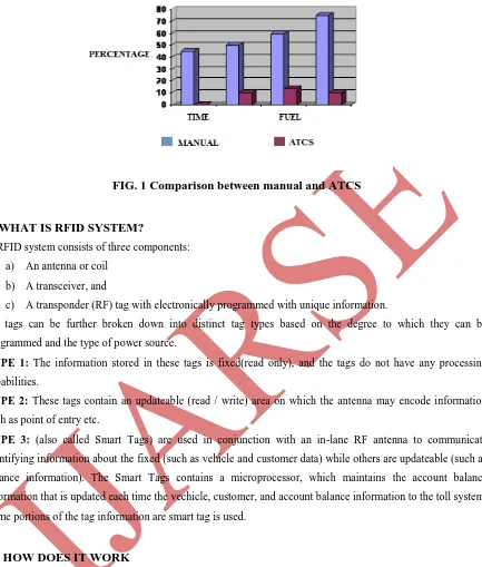
FIG. 1 Comparison between manual and ATCS
II WHAT IS RFID SYSTEM?
A RFID system consists of three components:
a) An antenna or coil
b) A transceiver, and
c) A transponder (RF) tag with electronically programmed with unique information.
RF tags can be further broken down into distinct tag types based on the degree to which they can be
programmed and the type of power source.
TYPE 1: The information stored in these tags is fixed(read only), and the tags do not have any processing
capabilities.
TYPE 2: These tags contain an updateable (read / write) area on which the antenna may encode information
such as point of entry etc.
TYPE 3: (also called Smart Tags) are used in conjunction with an in-lane RF antenna to communicate
identifying information about the fixed (such as vehicle and customer data) while others are updateable (such as
balance information). The Smart Tags contains a microprocessor, which maintains the account balance
information that is updated each time the vechicle, customer, and account balance information to the toll system.
Some portions of the tag information are smart tag is used.
III HOW DOES IT WORK
Automatic toll system using the RFID technology, it contains the RFID tag and the RFID reader module. RFID
tends the Radio Frequency Identification; they consist of the tags, which may be either active or passive.
3.1. Passive RFID tags do not possess their own power supply, the small electrical current induced in the
antenna by incoming radio frequency scan provides enough power for the tag to send the response. Because of
the power and cost concerns, the response of passive RFID tag is necessarily brief, its just an ID number. Shown
in Fig 2.
3.2. Active RFID tags must have a power source and may have longer ranges and larger memories than
passive tags as well as the ability to store the additional information sent by the transceiver. The technological
FIG.2 Passive tags
FIG.3 Active tags
Many active tags have the practical ranges of tens of meters and a battery life of up to several years. RFID is a
method of remotely storing and retreiving data using devices called RFID tags. An RFID tag is a small object,
such as an adhesive sticker, that can be attached to or incorporated into the product. RFID tags contain antennae
to enable them to receive and respond to radio frequency question from an RFID transceiver.
IV DATA CAPACITY
The amount of data storage of tag can vary, ranging from 16 bits on the low end to as much as several thousand
bits on the high end. Of course, the greater the storage capacity, the higher will be the price per tag.
V FREQUENCIES
Like all wireless communications, there are varieties of frequency or spectra through which RFID tags can
communicate with readers. Again, there are trade-offs among costs, performances and application requirements.
For instance, low-frequency tags are cheaper than ultra-high-frequency (UHF) tags, use of less power and are
able to penetrate non-metallic substances. They are ideal for scanning objects with high water content, such as
fruits, at close range. UHF frequencies offer better range and can transfer data faster. But they need more power
and are less likely to pass through some materials. UHF tags are best suited for use with wood, paper, cardboard
or clothing products. Compared to low-frequency tags, UHF tags might be better for scanning boxes of good as
they pass through a bay door into the warehouse. While the tag required for compliance mandates is narrowly
defined, a variety of tags will be required to solve specific operational issues.
VI A BRIEF INTRODUCTION TO 8051 MICROCONTROLLER:
A microcontroller is a single chip that contains the processor (CPU), non-volatile memory for the program (rom
or flash), volatile memory for input and output (RAM), a clock and an I/O control unit. Also called a "computer
on a chip," billions of microcontroller units (MCUS) are embedded each year in a myriad of products from toys
to appliances to automobiles. For example, a single vehicle can make use of seventy or more microcontrollers.
A microcontroller is a single chip which contains the processor (the CPU), non-volatile memory for the program
(rom or flash), volatile memory for input and output (RAM), a clock and an i/o control unit. Also called a
"computer on a chip," billions of microcontroller units (MCUS) are embedded each year in a myriad of products
from toys to appliances to automobiles. For example, a single vehicle can use 70 or more microcontrollers.
VII TYPICAL APPLICATION FOR RFID:
Automatic Vehicle identification Container/ Yard Management Document/ Jewellery tracking Patient Monitoring
VIII COMMON PROBLEMS WITH RFID:
Some common problems with RFID are reader and tag collisions. Reader collision occurs when the signal from
two or more readers overlap. The tag is not able to respond to simultaneous queries. Systems must be carefully
setup to avoid the problems. Tag collision occurs when many tags are present in the small area; but since the
read time is very fast, it is easier for vendors to develop system that ensure that tags respond one at a time.
IX CONCLUSION AND FUTURE SCOPE OF ATCS:
RFID is a highly stable and reliable technology. The RFID Automatic toll gate system can automatically detect
the identities of the vehicles, reading items in motion and tracking of the vehicles can be done accurately using
RFID. At first the system may seem like very costly but after a year of the system implantation high benefits
will be obtained as it will lead to lower operational costs and increased revenue generation . It not only reduces
the traffic related problems of the country but also proves to be a major technological development in the nation
which is the need of the hour as different countries all over the world are becoming technically strong.
REFERENCE
[1]Auther name, auther2, “ Title”, publication detail, Yr of publication. “8051 and embedded system” by
Mazidi and Mazidi
[2]Elisabeth Ilie-Zudor, Zsolt Kemeny, Peter gri and Laszlo Monostori, ―The RFID Technology and its
current applications.
[3]Kama Sundhare, ―Radio Frequency Identification Technology‖ Paper Presentation And PPT, on May 31,
2011.
[4]Charles Mutigwe and Farhad Aghdasi, ―Research Trends in RFID Technology.
[5]Christoph Jechlitschek, ―A Survey Paper on Radio Frequency IDentification (RFID) Trends.
[6]Khadijah Kamarulazizi and Dr. Widad Ismail, ―Electronic Toll Collection System Using Passive RFID Technology.
[7] Mr. R. M. Hushangabade and Prof. S.V. Dhopte, ―Implementation Of Rats For The Puepose Of Vehicle Training And Toll Tax Collection.
[8]Gabriel Nowacki, Izabella Mitraszewska, Tomasz Kamiński, ―The National Automatic Toll Collection System For The Republic Of Poland.
[9]Asif Ali Laghari, M. Sulleman Memon and Agha Sheraz Pathan, ―RFID Based Toll Deduction System