www.ijarse.com
366 |
P a g e
SIMULATION COMPARISON AND
IMPLEMENTAION OF DFIG WIND TURBINES
Koganti Bhanu Kumar
1, Maradugu Mahesh Kumar
2,
Yohan Babu Puvvadi
31, 2, 3
E.V.M College of Engineering and Technology (India)
ABSTRACT
With the increasing penetration of wind power into electric power grids, energy storage devices will be required
to dynamically match the intermittency of wind energy. This paper proposes a novel two-layer constant power
control scheme for a wind farm equipped with doubly fed induction generator (DFIG) wind turbines. Each
DFIG wind turbine is equipped with a super capacitor energy storage system (ESS) and is controlled by the
low-layer wind turbine generator (WTG) controllers and coordinated by a high-layer wind farm supervisory
controller (WFSC). The WFSC generates the active power references for the low-layer WTG controllers
according to the active power demand from or generation commitment to the grid operator; the low-layer WTG
controllers then regulate each DFIG wind turbine to generate the desired amount of active power, where the
deviations between the available wind energy input and desired active power output are compensated by the
ESS with PI controller. Simulation studies are carried out in MATLAB on a wind farm equipped with 15 DFIG
wind turbines to verify the effectiveness of the proposed control scheme.
Index Terms: Constant Power Control (CPC), Doubly Fed Induction Generator (DFIG), PI
Control, Energy Storage, Supervisory Controller, Wind Turbine.
I. INTRODUCTION
Wind Turbine generators (WTGs) are usually controlled to generate maximum electrical power from wind
under normal wind conditions. However, because of the variations of the wind speed, the generated electrical
power of a WTG is usually fluctuated. Currently, wind energy only provides about 1%–2% of the U.S.’s
electricity supply. At such a penetration level, it is not necessary to require WTGs to participate in automatic
generation control, unit commitment, or frequency regulation. However, it is reasonable to expect that wind
power will be capable of becoming a major contributor to the nation’s and world’s electricity supply over the
next three decades. For instance, the European Wind Energy Association has set a target to satisfy more than
22% of European electricity demand with wind power by 2030 [1]. In the U.S., according to a report [2] by the
Department of Energy, it is feasible to supply 20% of the nation’s electricity from wind by 2030. At such high
levels of penetration, it will become necessary to require WTGs to supply a desired amount of active power to
www.ijarse.com
367 |
P a g e
wind resources can cause high rates of change (ramps) in power generation [4], which is a critical issue for
balancing power systems. Moreover, to optimize the economic performance of power systems with high
penetrations of wind power, it would be desired to require WTGs to participate in unit commitment, economic
dispatch, or electricity market operation [5]. In practice, short-term wind power prediction [6] is carried out to
help WTGs provide these functions. However, even using the state-of-the-art methods, prediction errors are
present [5]. Under these conditions, the replacement power is supported by reserves, which, however, can be
more expensive than base electricity prices [7]. To enable WTGs to effectively participate in frequency and
active power regulation, unit commitment, economic dispatch, and electricity market operation, energy storage
devices will be required to dynamically match the intermittency of wind energy. In [8], the authors investigated
and compared different feasible electric energy storage technologies for intermittent renewable energy
generation, such as wind power. Currently, pumped water and compressed air are the most commonly used
energy storage technologies for power grids due to their low capital costs [9]. However, these two technologies
are heavily dependent on geographical location with relatively low round-trip efficiency. Compared with their
peers, batteries and super capacitors are more efficient, have a quicker response to demand variations, and are
easy to develop and ubiquitously deployable. Compared to batteries, super capacitors have a higher power
density, higher round-trip efficiency, longer cycle life, and lower capital cost per cycle [10]. Therefore, super
capacitors are a good candidate for short-term (i.e., seconds to minutes) energy storage that enables WTGs to
provide the function of frequency regulation and effectively participate in unit commitment and electricity
market operation. The use of super capacitors [10] or batteries [11]–[13] as energy storage devices for WTGs
has been studied by some researchers. However, these studies only focused on control and operation of
individual WTGs and did not investigate the issues of WTGs to participate in grid regulation. This paper
proposes a novel two-layer constant power control (CPC) scheme for a wind farm equipped with doubly fed
induction generator (DFIG) wind turbines [14], where each WTG is equipped with a supe rcapacitor energy
storage system (ESS). The CPC consists of a high-layer wind farm supervisory controller (WFSC) and
low-layer WTG controllers..
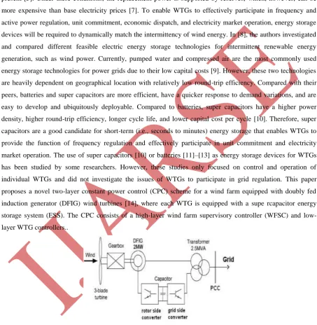
Fig. 1. Configuration of A DFIG Wind Turbine Equipped With a Super Capacitor ESS
Connected To a Power Grid
The high layer WFSC generates the active power references for the low layer WTG controllers of each DFIG
wind turbine according to the active power demand from the grid operator. The low-layer WTG controllers then
www.ijarse.com
368 |
P a g e
the available wind energy input and desired active power output are compensated by the ESS. Simulation
studies are carried out in PSCAD/EMTDC for a wind farm equipped with 15 DFIG wind turbines to verify the
effectiveness of the proposed control scheme
II. DFIG WIND TURBINE WITH ENERGY STORAGE
Fig. 1 shows the basic configuration of a DFIG wind turbine equipped with a super capacitor-based ESS. The
low speed wind turbine drives a high-speed DFIG through a gearbox. The DFIG is a wound-rotor induction
machine. It is connected to the power grid at both stator and rotor terminals. The stator is directly connected to
the grid, while the rotor is fed through a variable-frequency converter, which consists of a rotor-side converter
(RSC) and a grid-side converter (GSC) connected back to back through a dc link and usually has a rating of a
fraction (25%–30%) of the DFIG nominal power. As a consequence, the WTG can operate with the rotational
speed in a range of ±25%–30% around the synchronous speed, and its active and reactive powers can be
controlled independently. In this paper, an ESS consisting of a super capacitor bank and a two-quadrant dc/dc
converter is connected to the dc link of the DFIG converters. The ESS serves as either a source or a sink of
active power and therefore contributes to control the generated active power of the WTG. The value of the
capacitance of the super capacitor bank can be determined by
(1)
where Cess is in farads, Pn is the rated power of the DFIG in watts, VSC is the rated voltage of the super capacitor
bank in volts, and T is the desired time period in seconds that the ESS can supply/store energy at the rated power
(Pn) of the DFIG.
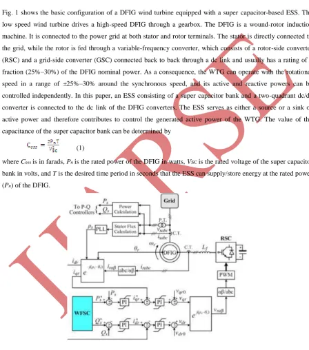
Fig. 2. Overall Vector Control Scheme of the RSC.
The use of an ESS in each WTG rather than a large single central ESS for the entire wind farm is based on two
reasons. First, this arrangement has a high reliability because the failure of a single ESS unit does not affect the
ESS units in other WTGs. Second, the use of an ESS in each WTG can reinforce the dc bus of the DFIG
www.ijarse.com
369 |
P a g e
III. CONTROL OF INDIVIDUAL DFIG WIND TURBINE
The control system of each individual DFIG wind turbine generally consists of two parts: 1) the electrical
control of the DFIG and 2) the mechanical control of the wind turbine blade pitch angle [14], [15] and yaw
system. Control of the DFIG is achieved by controlling the RSC, the GSC, and the ESS (see Fig. 1). The control
objective of the RSC is to regulate the stator-side active power Ps and reactive power Qs independently. The
control objective of the GSC is to maintain the dc-link voltage Vdc constant and to regulate the reactive power Qg
that the GSC exchanges with the grid. The control objective of the ESS is to regulate the active power Pg that
the GSC exchanges with the grid. In this paper, the mechanical control of the wind turbine blade pitch angle is
similar to that in [15].
3.1 Control of the RSC
Fig. 2 shows the overall vector control scheme of the RSC, in which the independent control of the stator active
power Ps and reactive power Qs is achieved by means of rotor current regulation in a stator-flux-oriented
synchronously rotating reference frame [16]. Therefore, the overall RSC control scheme consists of two
cascaded control loops. The outer control loop regulates the stator active and reactive powers independently,
which generates the reference signals i∗dr and i∗qr of the d- and q-axis current components, respectively, for the
inner-loop current regulation. The outputs of the two current controllers are compensated by the corresponding
cross-coupling terms vdr0 and vqr0 [14], respectively, to form the total voltage signals vdr and vqr. They are then
used by the pulse width modulation (PWM) module to generate the gate control signals to drive the RSC. The
reference signals of the outer-loop power controllers are generated by the high-layer WFSC.
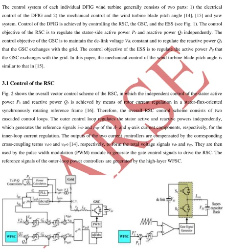
Fig. 3. Overall Vector Control Scheme of the GSC Fig. 4. Configuration and Control of the ESS
3.2 Control of the GSC
Fig. 3 shows the overall vector control scheme of the GSC, in which the control of the dc-link voltage Vdc and
the reactive power Qg exchanged between the GSC and the grid is achieved by means of current regulation in a
synchronously rotating reference frame [16]. Again, the overall GSC control scheme consists of two cascaded
www.ijarse.com
370 |
P a g e
which generates the reference signals i∗dg and i∗qg of the d- and q-axis current components, respectively, for the
inner-loop current regulation. The outputs of the two current controllers are compensated by the corresponding
cross coupling terms vdg0 and vqg0 [14], respectively, to form the total voltage signals vdg and vqg. They are then
used by the PWM module to generate the gate control signals to drive the GSC. The reference signal of the
outer-loop reactive power controller is generated by the high-layer WFSC.
3.3 Configuration and Control of the ESS
Fig. 4 shows the configuration and control of the ESS. The ESS consists of a super capacitor bank and a
two-quadrant dc/dc converter connected to the dc link of the DFIG. The dc/dc converter contains two insulated-gate
bipolar transistor (IGBT) switches S1 and S2. Their duty ratios are controlled to regulate the active power Pg that
the GSC exchanges with the grid. In this configuration, the dc/dc converter can operate in two different modes,
i.e., buck or boost mode, depending on the status of the two IGBT switches. If S1 is open, the dc/dc converter
operates in the boost mode; if S2 is open, the dc/dc converter operates in the buck mode. The duty ratio D1 of S1
in the buck mode can be approximately expressed as
(2)
and the duty ratio D2 of S2 in the boost mode is D2 = 1− D1. In this paper, the nominal dc voltage ratio VSC,n/Vdc,n
is 0.5, where VSC,n and Vdc,n are the nominal voltages of the super capacitor bank and the DFIG dc link,
respectively. Therefore, the nominal duty ratio D1,n of S1 is 0.5.
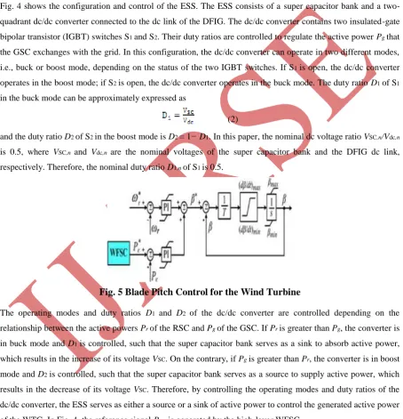
Fig. 5 Blade Pitch Control for the Wind Turbine
The operating modes and duty ratios D1 and D2 of the dc/dc converter are controlled depending on the
relationship between the active powers Pr of the RSC and Pg of the GSC. If Pr is greater than Pg, the converter is
in buck mode and D1 is controlled, such that the super capacitor bank serves as a sink to absorb active power,
which results in the increase of its voltage VSC. On the contrary, if Pg is greater than Pr, the converter is in boost
mode and D2 is controlled, such that the super capacitor bank serves as a source to supply active power, which
results in the decrease of its voltage VSC. Therefore, by controlling the operating modes and duty ratios of the
dc/dc converter, the ESS serves as either a source or a sink of active power to control the generated active power
of the WTG. In Fig. 4, the reference signal P∗ g is generated by the high-layer WFSC.
3.4 Wind Turbine Blade Pitch Control
Fig. 5 shows the blade pitch control for the wind turbine, where ωr and Pe (= Ps + Pg) are the rotating speed and
www.ijarse.com
371 |
P a g e
required to generate the maximum power, ωr and Pe are set at their reference values, and the blade pitch control
is deactivated. When the wind speed is below the rated value, but the WTG is required to generate a constant
power less than the maximum power, the active power controller may be activated, where the reference signal
P∗ e is generated by the high-layer WFSC and Pe takes the actual measured value. The active power controller
adjuststhe blade pitch angle to reduce the mechanical power that the turbine extracts from wind. This reduces
the imbalance between the turbine mechanical power and the DFIG output active power, thereby reducing the
mechanical stress in the WTG and stabilizing the WTG system. Finally, when the wind speed increases above
the rated value, both ωr and Pe take the actual measured values, and both the speed and active power controllers
are activated to adjust the blade pitch angle.
(3)
where k is a constant at a certain value of βi. Then, the maximum mechanical power Pmi,max that the wind turbine
extracts from the wind can be calculated by the well-known wind turbine aerodynamic characteristics
(4)
where ρi is the air density in kilograms per cubic meter; Ar =πR2 is the area in square meters swept by the rotor
blades with R being the blade length in meters; and CPi is the power coefficient, which is a function of both
tip-speed ratio λi and the blade pitch angle βi, where λi is defined by
(5)
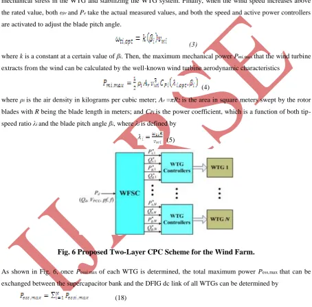
Fig. 6 Proposed Two-Layer CPC Scheme for the Wind Farm.
As shown in Fig. 6, once Pessi,max of each WTG is determined, the total maximum power Pess,max that can be
exchanged between the supercapacitor bank and the DFIG dc link of all WTGs can be determined by
(18)
Finally, depending on the relationship of Pess,d and Pess,max, the reference signals P∗ si (see Fig. 2) and P∗ gi (see
Fig. 4) of each WTG can be determined. Specifically, if |Pess,d| ≤ |Pess,max|, P∗ si and P∗ gi can be determined
directly, as shown in Fig. 6, where the partition coefficients ai’s are calculated by
www.ijarse.com
372 |
P a g e
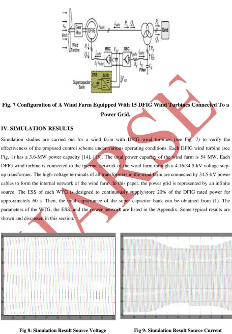
Fig. 7 Configuration of A Wind Farm Equipped With 15 DFIG Wind Turbines Connected To a
Power Grid.
IV. SIMULATION RESULTS
Simulation studies are carried out for a wind farm with DFIG wind turbines (see Fig. 7) to verify the
effectiveness of the proposed control scheme under various operating conditions. Each DFIG wind turbine (see
Fig. 1) has a 3.6-MW power capacity [14], [15]. The total power capacity of the wind farm is 54 MW. Each
DFIG wind turbine is connected to the internal network of the wind farm through a 4.16/34.5-kV voltage
step-up transformer. The high-voltage terminals of all transformers in the wind farm are connected by 34.5-kV power
cables to form the internal network of the wind farm. In this paper, the power grid is represented by an infinite
source. The ESS of each WTG is designed to continuously supply/store 20% of the DFIG rated power for
approximately 60 s. Then, the total capacitance of the super capacitor bank can be obtained from (1). The
parameters of the WTG, the ESS, and the power network are listed in the Appendix. Some typical results are
shown and discussed in this section.
www.ijarse.com
373 |
P a g e
Fig 10: Simulation Result Receiving Current Fig 11: Simulation Result Active Power
V CONCLUSION
This paper has proposed a novel two-layer CPC scheme for a wind farm equipped with DFIG wind turbines.
Each wind turbine is equipped with a super capacitor-based ESS with PI controller, which is connected to the dc
link of the DFIG through a two-quadrant dc/dc converter. The ESS serves as either a source or a sink of active
power to control the generated active power of the DFIG wind turbine with PI. Each individual DFIG wind
turbine and its ESS are controlled by low-layer WTG controllers, which are coordinated by a high-layer WFSC
to generate constant active power as required by or committed to the grid operator. Simulation studies have been
carried out for a wind farm equipped with 15 DFIG wind turbines to verify the effectiveness of the proposed
CPC scheme. Results have shown that the proposed CPC scheme enabled the wind farm to effectively
participate in unit commitment and active power and frequency regulations of the grid with PI controller. The
proposed system and control scheme provides a solution to help achieve high levels of penetration of wind
power into electric power grids.
REFERENCES
[1] ―Focus on 2030: EWEA aims for 22% of Europe’s electricity by 2030,‖Wind Directions, pp. 25–34,
Nov./Dec. 2006.
[2] 20% Wind Energy By 2030: Increasing Wind Energy’s Contribution toU.S. Electricity Supply, U.S.
Department of Energy, Jul. 2008.
[3] W. Qiao and R. G. Harley, ―Grid connection requirements and solutionsfor DFIG wind turbines,‖ in Proc.
IEEE Energy Conf., Atlanta, GA, Nov. 17–18, 2008, pp. 1–8.
[4] Wind Generation & Total Load in the BPA Balancing Authority: DOEB on Neville Power Administration,
U.S. Department of Energy [Online].Available:
www.ijarse.com
374 |
P a g e
[5] R. Piwko, D. Osborn, R. Gramlich, G. Jordan, D. Hawkins, and K. Porter, ―Wind energy delivery issues:
Transmission planning and competitive electricity market operation,‖ IEEE Power Energy Mag., vol. 3,
no. 6,pp. 47–56, Nov./Dec. 2005.
[6] L. Landberg, G. Giebel, H. A. Nielsen, T. Nielsen, and H. Madsen, ―Short-term prediction—An
overview,‖ Wind Energy, vol. 6, no. 3, pp. 273–280,Jul./Sep. 2003.
[7] M. Milligan, B. Kirby, R. Gramlich, and M. Goggin, Impact of ElectricIndustry Structure on High Wind
Peneration Potential, Nat. Renewable Energy Lab., Golden, CO, Tech. Rep. NREL/TP-550-46273.
[Online]. Available: http://www.nrel.gov/docs/fy09osti/46273.pdf
[8] J. P. Barton and D. G. Infield, ―Energy storage and its use with intermittent renewable energy,‖ IEEE
Trans. Energy Convers., vol. 19, no. 2, pp. 441– 448, Jun. 2004.
[9] D. Rastler, ―Electric energy storage, an essential asset to the electric enterprise: Barriers and RD&D
needs,‖ California Energy Commission Staff Workshop Energy Storage Technol., Policies Needed Support California’s RPS Goals 2020, Sacramento, CA, Apr. 2, 2009.
[10] C. Abbey and G. Joos, ―Supercapacitor energy storage for wind energy applications,‖ IEEE Trans. Ind.
Appl., vol. 43, no. 3, pp. 769–776, May/Jun. 2007.
[11] B. S. Borowy and Z. M. Salameh, ―Dynamic response of a stand-alone wind energy conversion system
with battery energy storage to wind gust,‖ IEEE Trans. Energy Convers., vol. 12, no. 1, pp. 73–78, Mar.
1997.
[12] M.-S. Lu, C.-L. Chang, W.-J. Lee, and L. Wang, ―Combining the wind power generation system with
energy storage equipments,‖ IEEE Trans. Ind. Appl., vol. 45, no. 6, pp. 2109–2115, Nov./Dec. 2009.
[13] A. Yazdani, ―Islanded operation of a doubly-fed induction generator (DFIG) wind-power system with
integrated energy storage,‖ in Proc. IEEE Canada Elect. Power Conf., Montreal, QC, Canada, Oct. 25–26,
2007, pp. 153–159.
[14] W. Qiao, W. Zhou, J. M. Aller, and R. G. Harley, ―Wind speed estimation based sensorless output
maximization control for a wind turbine driving a DFIG,‖ IEEE Trans. Power Electron., vol. 23, no. 3, pp.
1156–1169, May 2008.
[15] W. Qiao, G. K. Venayagamoorthy, and R. G. Harley, ―Real-time implementation of a STATCOM on a
wind farm equipped with doubly fed induction generators,‖ IEEE Trans. Ind. Appl., vol. 45, no. 1, pp. 98–
107, Jan./Feb. 2009.
[16] D. W. Novotny and T. A. Lipo, Vector Control and Dynamics of ACDrives. Oxford, U.K.: Oxford Univ.