70
Distance Measurement Using Stereo Vision
P
1
P
Sheetal Nagar, P
2
P
Prashant Mavi
1Department of Electronics and communication Engineering, IIMT, Greater Noida (India)
2
Department of Electronics and communication Engineering, IIMT, Greater Noida (India)
ABSTRACT
In this paper, we propose a novel concept of relativedistance measurement using Stereo Vision Technology and discuss its
implementation on real-time image processor. We capture two images using two CCD cameras and compare them. Distance
is calculated for the object using a mathematical calculation using matlab algorithm. This algorithm is based on the concept
of the triangulation method for distance (Proved Later), we can thus get the relative distances of objects in front of the
camera. The output is displayed on a Computer screen in the form of a distance image. This system works in real time on a
full PAL frame rate (720 x 576 active pixels)
Keywords: Stereo Vision, Relative Distance Measurement.
I.INTRODUCTION
As the world progresses towards human comfort and automation, distance perception forms an integral part of
automated navigation and motion. There are several techniques that are implemented for the purpose of obstacle
detection and distance perception. Some popular methods include use of infrared sensors, ultrasonic sensors,
common RADAR technology, a combination of digital camera and Laser, etc. Most of these methods involve recording
of time between transmission and receiving of the signal. Other systems may use Laser stripping, optical flow, etc.
However the sensors used in these methods are very strongly affected by environmental conditions like temperature, fog etc.
Also, these methods provide information only about the distance of the object and not its geometry. The image sensor that we
use, i.e. the camera is less affected by environmental parameters and provides information about the distance of the
object too which can be further utilized for navigation and other such purposes.
We cannot perceive distance of an image from its two dimensional representation. Distance here represents the distance of
objects in the image from the center of two cameras. To extract distance we use a pair of images called stereo images. These
images are of the same scene captured by two cameras separated by a horizontal distance. The correlation between object
positions in the two images gives us the distance information that we seek. This is the concept of stereo vision and
triangulation.
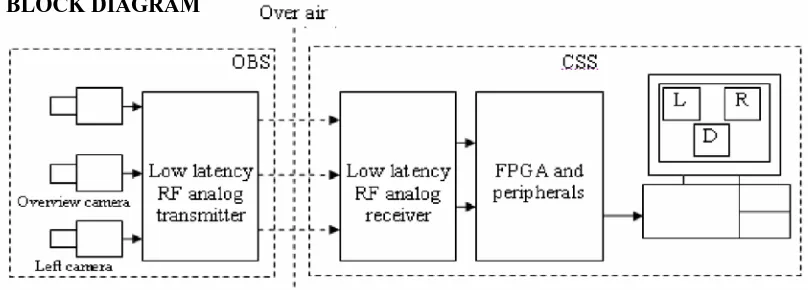
II.SYSTEM BLOCK DIAGRAM
www.ijiset.com
71
DESCRIPTION
Inputs received from two cameras (left and right) placed in the field are transmitted through an analog transmitter-receiver
pair. These images are received at the processing station. Images are processed to calculate the distance with the help of
matlab algorithm and hence distance of the object is calculated. The output is displayed on computer screen in the form of
centimeter. Also, the output in centimeter format is shown on a computer monitor in full frame size as well as full frame rate.
An overview camera may also be provided to give the user a better perspective of the situation.
III.STEREO VISION TECHNOLOGY
Stereo means having 3 dimensions. It comes from the Greek word ‘Stereos’ which means firm or solid. Stereo vision
technology is where 3-D images are used to judge the depth, contrast and distance of objects in our surroundings. 3-D image
processing systems have reached the mainstream and are now embedded in a wide range of products including security and
surveillance devices, industrial robotics, and autonomous vehicles. This concept of stereo vision is based on the human ‘Eyes
and Visual System’. This is ‘Binocular Vision’. It is nothing but the ability to use two eyes to see an object as one. The
human eye catches two images with the help of two eyes and integrates them into one. Thus we can achieve 3-D vision and
depth perception. For instance, when you hold up an apple and look at it with just your right eye, the image will be different
from the one you see with only your left. Not only that, you will notice that the position of the apple seems to have shifted,
relative to the background. The apple will seem to be more to the left side when you look with your right eye, and conversely
more to the right side when you look with your left. Yet, when the two images are sent from our eyes to the brain, it processes
the two as one image. As the image of the apple from both eyes merged as one, it seems to us to be sharply-defined, detailed
72
This concept is implemented in the electronic world with two cameras, which mimic the way the human eye captures twoimages. The two cameras are placed in an Epipolar fashion i.e. they are displaced horizontally. The cameras are then modeled
whereby they will see slightly different projections of the world view and thus capture the left and right images. The
correlation between these two images gives us the depth information that we seek. We can also obtain information about the
geometry of the objects in the images.
IV.ALGORITHM DETAILS
Mathematical Representation:
P1 / P = D1 / D.
Where,
P1 represents pixel displacement from centre
P represents total pixel displacement of the camera
D1 stands for angle displacement from centre
D stands for total angle displacement of the camera
V. Graphical Representation:
Object recognized and observed to be at the left side of the camera from the line of centre.
The camera is rotated anti clock wise in steps of 18 degrees till the object centroid fall in the right quadrant of the camera, then
www.ijiset.com
73
The camera is rotated anti clock wise in steps of 18 degrees till the object centroid fall in the right quadrant of the camera, thenthe parameters are calculated which are needed to determine the angle displacement from the line of centre of the camera.
Once the displacement angle is calculated, the object distance can be determined by using the following formulas:
Assuming that the object is on point A, left camera to be on point B and right camera to be on point C.
The parameters know are: D1, D2 and length of BC i.e. 20cms.
The parameter to be calculated is AE which is median to the triangle ABC; this median is the real distance of the object from the gadget
.
Thus to calculate AE, following calculations must be executed:
In triangle BFC,
Sin (D2) = BF/BC BF=BC * Sin (D2) as D2 and BC (20cms) are known
-- Step 1
In triangle ABF,
Sin (D3) = BF/ AB AB= BF/ Sin (D3) as D3=180-(D1+D2) and BF is calculated from the above step
-- step 2
In triangle ABG,
74
BE=BC/2 i.e. BE=10cms as median divides the base into two equal parts.In triangle AGE,
AE = √(AGP
2
P
+ GEP
2
P
) as GE = BE-GB and AG is calculated from the step 3
Thus median AE is calculated, the distance of the object from the gadget
.
VI. PROJECT SET-UP
As described, for implementation of stereovision two cameras will be employed, separated apart by a calculated distance,
these cameras will be mounted on two individual stepper motors controlled by MATLAB program, these motors will be
connected to the microcontroller which in turn will be connected to the computer via serial port, on recognizing the object with
respect to its shape and color (matching with the database object), the MATLAB computation program will command the
motors to make the object in the centre of image taken by both the cameras.
Web Camera mounted over stepper motor, analogous to human eyes. Once the object is aligned to the centre, the matlab
software will count the deviation of the cameras from the centre thus calculating the angle formed from their straight line of
sight. Therefore on calculating the angle formed and knowing the distance between the cameras, the distance from the object can be
calculated.
www.ijiset.com
75
This hardware works in conjunction with computer, it receives serial data from computer via serial port (DB-9) and acts in accordance to the commands. Two stepper motors (two phase with 0.9 degrees step angle) and a buzzer is connected to this
circuit. Stepper motors acts as a base for left and right camera i.e. cameras are mounted on these stepper motor so as they can
be rotated to clock wise or anti clock wise direction as required. Buzzer is used to give audible notification. All these devices
are in control of microcontroller which serially accepts commands from computer and works in accordance to that.
Commands:
1. a<no. of steps> - rotates right stepper motor in clock wise direction, with specified no. steps.
2. b<no. of steps> - rotates right stepper motor in anti clock wise direction, with specified no. steps.
3. c<no. of steps> - rotates left stepper motor in clock wise direction, with specified no. steps.
4. d<no. of steps> - rotates left stepper motor in anti clock wise direction, with specified no. steps.
5. x – Buzzer on
6. y – Buzzer off
VIII. DISTANCE MESUREMENT OUTPUT FOR DIFFERENT DISTANCES
Here we are representing some experimental results for different distances. With the help of this distance measurement
stereo vision system we can measure the distance which must be at least 20 cm far from the system. There are five windows
for getting the result from this system. First window shows the output of left camera second window shows the output of right
camera.
After taking the preview with the help of two cameras we store the object in database. Now when we start the distance
measurement system then after taking the preview of the object, system will search the object in database and after matching
the object result will display on the screen. There are another window for showing the position of object after matching the
object in database and make a bounding box of the object. Now matched database object is shown in another window matched
76
IX. CONCLUSION
In this paper we have proposed a novel concept of Implementation of stereo vision for distance measurement of the
object by the triangulation method always gives improper results and failure. Thus a reliable method is proposed and results
are shown in the theses. Practically in this project need a proper lightening and no moving object in background when we run
this project. In such practical conditions this technique is giving exact results. There are threshold values used in MATLAB
program to recognize the objects and measure the distance of the object which is used in different fields. There are many
aspects related to object recognition which are not considered like if object is in the same color of the back ground color.
APPLICATIONS
1. Security and Surveillance Devices
2. Industrial Robotics
3. Autonomous Vehicles
4. Calculation of Contour Maps
REFERENCES
[1] S. Birchfield, C. Tomasi, “Depth Discontinuties by Pixel-toPixel Stereo”, International Journal of Computer Vision,
Vol. 35(3), pp. 269-293, (1999).
[2] F. Tombari, S. Mattoccia, L. Stefano, E. Addimanda, “Near real-time stereo based oneffective cost aggregation”, 19th
International Conference on Pattern Recognition, pp. 1-4, (2008).
[3] L. Wang, M. Liao, G. Minglun, Y. Ruigang, “High quality real-time Stereo using Adaptive Cost aggregation and Dynamic
Programming”, Proceedings of the Third International Symposium on 3D Data Processing, Visualization, and
Transmission, pp. 798-805, (2006).
[4] Q. Yang, C. Engels, A. Akbarzadeh, “Near Real-time Stereo for Weakly-Textured Scenes”, British Machine Vision