Performance Analysis of a 10 Hp Induction
Machine Drive Employing Vector Control
Naveen Asati 1, Gourav Kumar Shrivastava2
Associate Professor, Dept. of EEE, LNCT, BHOPAL, Madhya Pradesh, India1 PG Student [Power Electronics], Dept. of EEE, LNCT, BHOPAL, Madhya Pradesh, India 2
ABSTRACT: This Paper deals with the SPWM(Sinusoidal Pulse Width Modulation) technique to control the Induction machine with FOC (Field Oriented Control) scheme to enhance the performance and stability of the system. Speed of the IM(Induction Machine) has been controlled by using a PI controller. Two more PI controllers have been used to output voltage of the PWM inverter through which IM has been fed. The feasibility of the proposed control scheme has been verified in the MATLAB/SIMULINK environment the dynamic response of the system has been verified with better response. The system response with step changes in rotor speeds and step changes in load torque has been concluded to be satisfactory with the results obtained.
KEYWORDS: Vector Control, Sinusoidal Pulse Width Modulation (SPWM) Technique, Squirrel cage Induction Machine (SCIM).
I. INTRODUCTION
In the present scenario IM has been used in many applications, such as hybrid electric vehicle, wind energy conversion system, crane drives and lifts etc. Different electrical motors have been shared the market in recent days. IM has been lagging because of its poor dynamic response under change in speed and load. DC machine is very simple and effective. However DC machines maintenance cost and price are high. As a consequence of low maintenance cost low price, high starting torque, simple construction, good acceleration, and its robustness, the SCIM(Squirrel Cage Induction Machine) has been a better choice for any applications. [1]. In this paper simulation of an SCIM with FOC technique which gives good dynamic response has been done in MATLAB/SIMULINK software.
II. SYSTEM CONFIGURATION AND PRINCIPLE OF OPERATION:
Fig. 1 shows the system configuration of a SCIM drive. An SCIM of 10HP rating has been employed. To facilitate the variable speed operation of the drive it has been fed from a two level PWM inverter which employs The three phase supply of 415V, 50Hz has been rectified and filtered using an uncontrolled rectifier and an LC filter. The converters have been connected with a common DC link. The VSI(Voltage Source Inverter) has been controlled using SPWM technique for inverting operation. The mid point of the VSI is connected to three phase SCIM. The objective of the VSI is to control the speed of SCIM using FOC scheme.
Source
Phase
3
ctifier Re Diode
Filter RC
Inverter
IM Phase 3
III. CONTROL ALGORITHM
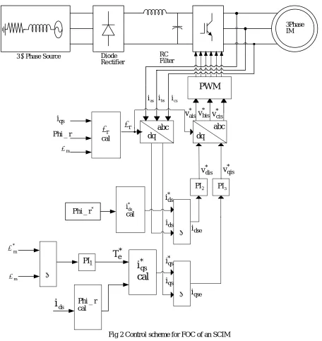
The block diagram of the proposed control scheme has been shown in Fig.2. The inverter controls the speed of the SCIM under step change in speed and load. The control scheme employed for the two level SPWM inverter is as follows.
Source Phase 3
ctifier Re Diode
Filter RC
IM Phase 3
r
qs i
ds i
* m
qse i * ds i
dse i
PWM
* ais
v v*bisv*cis
abc dq
* dis v v*qis
2
PI PI3
* qs i
* e
T
abc dq
cal i*
ds
cal
i
*qs1 PI
m
cal r _ Phi
ds
i
*
r _ Phi
qs i
r _ Phi
m
cal
r
as
i ibs ics
PWM
Fig 2 Control scheme for FOC of an SCIM By comparing the reference Speed ( *
m
) with the sensed motor speed (
m) an error is obtained as,)
n
(
)
n
(
)
n
(
* mm
me
(1)The motor speed error is processed through a PI controller (PI1) which provides reference torque component (
T
e*) used)
n
(
k
)}]
1
n
(
)
n
(
{
k
[
)
1
n
(
T
)
n
(
T
* P1 me me I1 mee *
e
(2)The rotor flux linkage (
r) is given byr ds m r
ST
1
I
*
L
(3)Lm=motor Mutual Inductance.
Ids=actual direct axis current component.
Tr = rotor time constant.
Reference quadrature current component(i* )
qs is given by
r m * e r * qs PL 3 T L 2 i
(4)
Lr=rotor inductance
P=no of poles of machine
Reference direct current component
(
i
*)
ds is given by
m * r * ds
L
i
(5)* r
=reference rotor flux=0.5 Slip speed of the machine (
slip)r r sq m slip
T
i
L
(6)Synchronous speed of the machine is given by
slip m
sync
(7)Three phase SCIM currents (ias, ibs, and ics) are obtained by sensing two phase currents (ias and ibs) and third phase
current is estimated with consideration that instantaneous sum of three phase currents is zero for three wire system as, 0 ) n ( i ) n ( i ) n (
ias bs cs (8)
The θr (transformation angle for parks transform) is obtained from speed ωm as,
dt ) n ( . P ) n ( m
r
(9) where P is the number of pole pairs here its value is 4. These PMSG currents are transferred to dq-axis currents as,
cs i bs i as i ) 3 4 s sin( ) 3 2 s sin( s sin ) 3 4 s cos( ) 3 2 s cos( s cos 3 2 qs i ds i (10)
The reference d-axis current (i*ds) is compared with the actual d-axis current (ids) and error is obtained as, ) n ( i ) n ( i ) n (
idse *ds ds (11)
This error is processed through a PI controller (PI2) to obtain voltage vdis as,
)
n
(
i
k
)}]
1
n
(
i
)
n
(
i
{
k
[
)
1
n
(
v
)
n
(
v
*dis
*dis
P2 dse
dse
I2 dse (12) where ki2and kp2 are proportional and integral gain constantsSimilarly, the reference d-axis current ( * qs
i ) is compared with the actual q- axis current (iqs) and error is given as,
) n ( i ) n ( i ) n (
iqse *qs qs (13)
This error is passed through a PI controller (PI2) to obtain synchronous reference frame voltage vqis as, ) n ( i k )}] 1 n ( i ) n ( i { k [ ) 1 n ( v ) n (
where kp3 and ki3 are proportional and integral gains respectively.
The synchronous reference voltages
v
*dis and v*qis are transformed to three phase voltages * bis * ais,vv and
v
*cisas, ) n ( * qis v ) n ( * dis v ) 3 4 s sin( ) 3 4 s cos( ) 3 2 s sin( ) 3 2 s cos( s sin s cos ) n ( * cis v ) n ( * bis v ) n ( * ais v (15)
The angle θr is obtained as given in Eq. (9).
Three phase reference voltages (
v
*ais,v
*bisandv
*cis) are fed to PWM controller to generate switching pulses for a VSI.IV. MATLAB IMPLEMENTATION
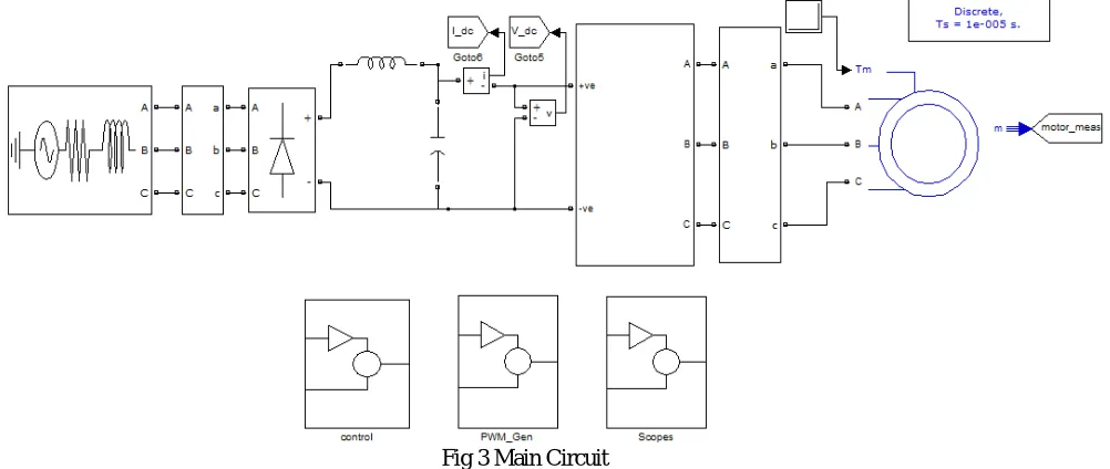
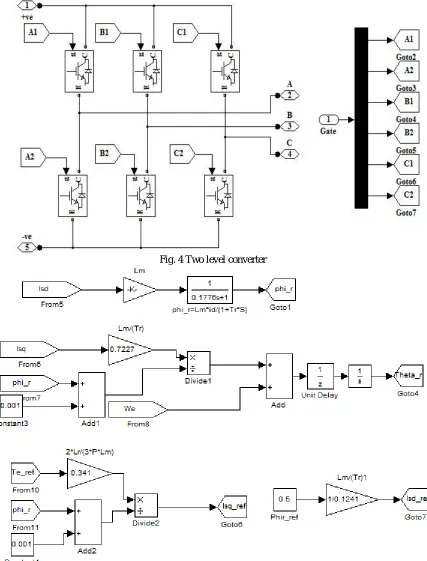
In this section the MATLAB based model of Induction machine drive with vector control has been given shown in Fig. 3. A two level VSc is used which is controlled to run the machine in vector mode. The VSI and SCIM models are taken from the tool box of SIM power systems. A model of two level converter is shown in Fig. 4. For the control of converter the control schemes are shown in Fig. 5 and Fig. 6. The command input to the system is load torque of the machine. The using model of VSC control is designed as shown in Fig. 5. The reference torque is generated by processing speed error. Actual motor speed is compared with the reference speed and the speed error is processed through a PI controller to generate reference torque component. The current
i
*qs is obtained from the reference torque and it is compared with iqs. A PI controller processes the error obtained and produces* qs
v
. Actual direct axis current is compared to reference value obtained from the rotor flux. This resembles d-axis current error. A PI controller processes the error and providesv
*ds. The d and q axis voltages are transformed to stationary frame using dq-abc transformation. The transformation angle is taken from the SCIM measurements. The obtained stationary frame voltagesv
*as,
v
*bs,
and
v
*cs are compared with a carrier signal built using a ‘repetitive sequence block’. The resultant is given to the upper switch and its negation is given to lower switch. “Go to” and “From” blocks are used to reduce complexity in the circuit as shown in fig. 7.Fig. 4 Two level converter
Fig.6 Control Algorithm-Part II
V. RESULT AND DISCUSSION
The simulation model of a IM drive with vector control has been developed using MATLAB R2009a. Figs (8-10) shows the results obtained at VSC under steady condition and step change in both speed and load torque.. These results are obtained in terms of SCIM currents (isabc), DC link voltage (Vdc), DC link current through VSC, electromagnetic
torque ( * e
T ).
Performance of IM drive with step change in speed and load torque:
Fig. 8 and 9 Shows the performance of the system during starting. During starting it has been observed that the DC link voltage has been maintained constant and the rated torque has been developed. The drive achieves the rated speed in 0.5sec. The recorded performance of the proposed drive shows the efficacy of the presented scheme.
The drive is running at 156 rps which is the rated reference speed. The electromagnetic torque (Te) developed has been
meeting the demand of the load torque (TL) which is a function of speed as evident from the results. The DC link
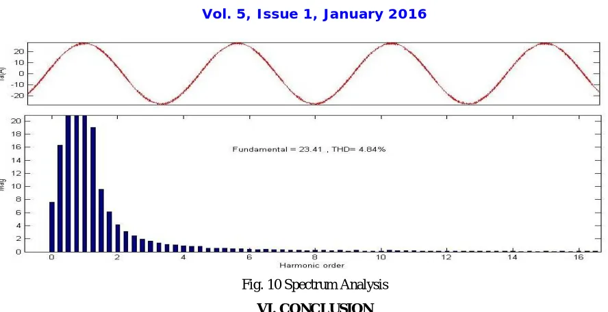
voltage is maintained at its reference value and three phase stator currents are observed balanced and sinusoidal.The speed has been recovered validating the control scheme. Fig. 10 shows the spectrum analysis of phase ‘a’ current from which it has been observed that the THD level is within the IEEE standards. The simulation results conclude that step change in rotor speed takes 0.3 sec to reach steady state condition. The speed of the IM drive has been maintained constant under variable torque condition.
Fig8 Voltage, Current responses of system under step change in load and speed
Fig. 10 Spectrum Analysis
VI. CONCLUSION
Thus it allows each node with message to decide whether to copy the message to a path node by optimizing its transmission effort in order to provide a sufficient level of message delay. Using a channel selection scheme provides spectrum utilization while it minimizes the interference level to primary system. Using trustworthy algorithm, it improves the trustworthiness of the Spectrum sensing in CR-Networks. It enables network nodes to adaptively regulate their communication strategies according to dynamically changing network environment.
CONCLUSION
This paper concludes that the FOC scheme is a good approach for controlling the IM because the IM response to torque change is very quick and precise. Control scheme has been studied for variable torque operation of a IM drive system using a two level voltage source converter. A field oriented control has been used for machine side VSC. The performance of the SCIM drive has been found satisfactory under change load torque.
APPENDIX
Specifications of Induction machine
7460W, 415V, 50Hz, 4 pole , 1450rpm, 40 Nm, Stator resistance 0.7384ohm, stator inductance - 0.003045H, rotor resistance 0.7402 ohm, rotor inductance -0.003045H, mutual inductance 0.1241H.
REFERENCES
1 P. C. Sen, “Electric Motor Drives and control past, present, and Future” IEEE Trans. on Ind. Elec., vol. 37, no.6, Dec, 1990. 2 M. P. Kazmierkowski, F. Blaabjerg, and R. Krishnan, Control in Power Electronics, Academic press, California, 2002. 3 Peter Vas, Sensorless Vector and Direct Torque Control, Oxford University Press, Newyork, 1998.
4 S.Jain, S.Sharma, and R.S. Mandloi “Improved Power Quality AC Drive Feeding Induction Motor”, IJETEE, vol.2, pp-35-40, Issue.1, Apr. 2013.
5 B.N. Singh, B.Singh, and B. P. Singh, “Performance analysis of closed loop field oriented cage induction motor drive” Journal of Electrical Power systems and research, vol. 29, no.2, pp.69-81, Feb. 1994.
6 A.V. RaviTeja, and C. Chakraborthy, “A novel model reference adaptive controller for estimation of speed and stator resistance for vector controlled induction motor drives” Proc. IEEE, Bari, 2010, pp. 1187-1192.