Design & Analysis of Grid Connected Permanent Magnet
Synchronous Generator Using Fuzzy Logic Controller
N.Navya & C. MD.ShareeF
1PG Scholar, Dept of EEE(PE&ED), VEMU Institute of Technology, Andhrapradesh, India, Email: [email protected]
2Assistant Professor, Dept of EEE, VEMU Institute of Technology, Andhrapradesh, India, Email: [email protected]. Abstract--A comprehensive control of a
wind turbine system connected to an industrial plant is discussed in this paper where an algorithm has been developed allowing a control structure that utilizes a four-leg inverter connected to the grid side, to inject the available energy, as well as to work as an active power filter, mitigating load current disturbances and enhancing power quality. A four-wire system is considered with three-phase and single-phase linear and nonlinear loads. During the connection of the wind turbine, the utility side controller is designed to compensate the disturbances caused in presence of reactive, non-linear and/or unbalanced single- and intra-phase loads, in addition to providing active and reactive power as required. When there is no wind power available, the controller is intended to improve the power quality using the DC-link capacitor with the power converter attached to the grid. The main difference of the proposed methodology with respect to others in the literature is that the proposed control structure is based on the Conservative Power Theory decompositions. This choice provides decoupled power and current references for the inverter control, offering very flexible, selective and powerful functionalities. Real time software benchmarking has been conducted in order to evaluate the performance of the proposed control algorithm for full real-time
implementation. The control methodology is implemented and validated in hardware-in-the-loop (HIL) based on Opal-RT and a TI DSP. The results corroborated our power quality enhancement control, and allowed to exclude passive filters, contributing to a more compact, flexible and reliable electronic implementation of a smart-grid based control.
Index Terms--Conservative power theory,
Four-leg voltage source converter,
Hardware-in-the-loop, Power quality, Permanent magnet synchronous generator.
I INTRODUCTION
The global capacity of installed wind turbines has rapidly increased in the last few years, by 2013 there were about 300 GW of installed wind capacity [1]. There have been tremendous developments in the wind turbine industry supporting this energy source as a mainstream renewable resource, with competitive costs in $/kWh when compared to traditional fossil fuel power plants. This development is due to the advancement in electrical generators and power electronics. The main issue with renewable energy is that the power is not always available when it is needed.
and to support grid voltage during faults and voltage sags [2]-[4].
Several control approaches have been introduced in the literature for wind turbine in standalone and grid connected systems [5], [6]. The machine side controllers are designed to extract maximum power point from wind using hill-climbing control, fuzzy-based, and adaptive controllers [7], most of the time based on field-oriented or vector control approach. The grid side controllers are designed to ensure active and reactive power is delivered to the grid [8], [9].
In order to allow the theoretical framework, different power theories have been proposed and implemented in electrical power systems to analyze current and
voltage components, such as the
instantaneous power (PQ) theory for a three-phase system made by Akagi [10]. In PQ theory, the three-phase is transformed into a two-phase reference frame in order to extract active and reactive components in a simplified manner. A three-phase power theory in a broader perspective has been introduced, known as the Conservative Power Theory (CPT) [11], where the current and voltage components are derived in the three-phase form, without requiring any reference-frame transformation [12]. The performance of these theories has been compared in references [13], [14].
This paper proposes a control structure in three-phase four-wire systems that provides more functionality to the grid side converter of a wind turbine system using the conservative power theory (CPT) as an alternative to generating different current references for selective disturbances compensation, where both single- and
three- phase loads are fed. Three-phase, four-wire inverters have been realized using conventional three-leg converters with “split-capacitor” or four-leg converters [15],[16]. In a three-leg conventional converter, the ac neutral wire is directly connected to the electrical midpoint of the DC bus. In four-leg converter, the ac neutral wire connection is provided through the fourth
switch leg. The “four-leg” converter topology has better controllability than the “split-capacitor” converter topology [17]-[19]. The considered system consists of single- and three-phase linear and nonlinear (balanced and unbalanced) loads. The CPT is used to identify and to quantify the amount of resistive, reactive, unbalanced and nonlinear characteristics of a particular load under different supply voltages condition for four-wire system. This paper is the journal version of our presented work in the 2015 IAS annual meeting [20]. The organization of the paper is as follows: Section II presents the utility connected wind turbine system considered in this paper. In Section III, a brief review of the CPT for three-phase circuits is presented. Section IV presents the control design of the back-to-back converter system. Section V is dedicated to the experimental verification of the proposed control structure through a real time hardware-in-the-loop (HIL) setup. Finally, the conclusion of this paper is presented in Section VI.
a back-to-back converter with a permanent magnet synchronous generator (PMSG) connected to the same bus with the loads. The loads are a combination of linear and highly inductive loads causing harmonics at the PCC.
Fig 4. 1. Single line diagram of the addressed industrial system with wind turbine system.
The model of the wind turbine system considered in this paper is described in [21]. The generator of the system is based on the Permanent Magnet Synchronous Generator (PMSG). The model of the PMSG used in this paper is presented in [20].
III CONSERVATIVE POWER THEORY
The Conservative Power Theory, proposed by [11], decomposes the power and current in the stationary frame, according to terms directly related to electrical characteristics, such as average power transfer, reactive
energy, unbalanced loads and
nonlinearities. Assuming a generic poly-phase circuit under periodic operation (period T), where (𝑣) and (𝑖) are, respectively, the voltage and current vectors, and (𝑣̂) is the unbiased integral of the voltage vector measured at a given
network port (phase variables are indicated with subscript “𝑚”), the CPT authors define [13]:
Instantaneous active power:
Instantaneous reactive energy:
The corresponding average values of (1) and (2) are the active power and reactive energy defined in (3) and (4), respectively as follows:
The phase currents are decomposed into three current components as follows: Active phase currents are defined by:
where (𝐺𝑚) is the equivalent phase conductance.
Reactive phase currents are given by:
Void phase currents are the remaining current terms:
where they convey neither active power nor reactive energy.
The active and reactive phase currents can be further decomposed into balanced and unbalanced terms.
The balanced active currents have been defined as:
and such currents represent the minimum portion of the phase currents, which could be associated with a balanced equivalent circuit, responsible for conveying the total active power (𝑃) in the circuit, under certain voltage conditions.
The balanced reactive currents have been defined as:
and they represent the minimum portion of the phase currents, which could be associated with a balanced equivalent circuit, responsible for conveying the total reactive energy (𝑊) in the circuit.
The imbalanced active currents are calculated by difference between (5) and (8):
In the same way, the imbalanced reactive currents are
Thus, the total imbalance phase current vector is defined as:
The current vector can be given as:
IV. CONTROL DESIGN
A. Machine Side Controller
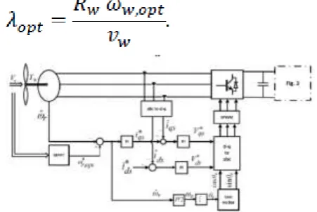
The purpose of the machine side converter is to track the optimum point of the rotor to extract the maximum power existing in the turbine. For a given wind turbine, the maximum power occurs at the maximum power coefficient of the turbine [22]. For a given wind speed there is an optimum rotor speed that gives the optimum tip speed ratio.
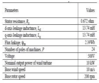
Fig. 2 Control scheme of machine side converter.
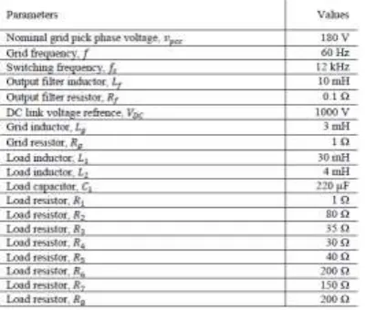
Then, this optimum rotor reference is subtracted from the measured rotor speed to produce the speed error. As shown in Fig. 2 a rotor speed controller is designed to generate the quadrature current reference to the internal current controller. The direct current reference in this paper is set to zero. The detail of the controller design procedure is presented in [23]. The parameters and values of the grid side system and the load are illustrated in Table I.
B. Grid Side Controller
In this section the current-controlled voltage source inverter is designed and modeled. The control scheme for the four-leg grid side inverter is shown in Fig. 3.
Fig. 3 Control scheme of grid side converter.
Fig. 3 illustrates the schematic diagram of the grid-tied four-leg inverter unit, consisting of a four-leg voltage source converter (VSC) and the network load that are connected to the distribution network at PCC. The inductance of the filter is 𝐿𝑓 and 𝑅𝑓 is the ohmic loss of the inductor. The machine side converter of Fig. 2 is connected in parallel with the VSC DC-link capacitor 𝐶 . It is shown that the grid side inverter unit is controlled in an 𝑎𝑏𝑐 -reference frame. 𝑣𝑝𝑐𝑐 is dictated by the grid representing the PCC/load voltage. The control objective is to allow the wind source to inject its available energy, as well as to work as an active power filter for improving power quality based on CPT functionalities. Fig. 4 shows the circuit, containing both balanced and unbalanced linear and non-linear loads. The parameters and values of the grid side system and the load are illustrated in Table II.
Fig.4 Schematic diagram of the configurable load in Fig. 3.
TABLE II
The inverter unit control system consists of two feedback control loops [14]. The first loop demonstrated in Fig. 5 is a fast loop controlling the output current, showing that 𝑖𝑜,𝑎𝑏𝑐𝑛 can rapidly track their respective reference commands 𝑖𝑜,𝑎𝑏𝑐𝑛∗ , while 𝑖𝑜,𝑛 ∗ is determined as 𝑖o,𝑛 ∗ = −( 𝑖𝑜,𝑎 ∗ + 𝑖𝑜,𝑏 ∗ + 𝑖𝑜,𝑐 ∗ ). The outer loop depicted in Fig. 8 is a slower loop regulating the link voltage. The DC-link keeps the power balance between the power which is delivered to the system in the output of the inverter and the power in the DC-link. The desired inverter output current is the summation of the active current provided from the wind (𝑖𝑎𝑐𝑡𝑖𝑣𝑒) and the compensation of unwanted load current disturbances delivered by the CPT technique. The block diagram of the system in the “𝑠” plane shown in Fig. 5 is designed in an 𝑎𝑏𝑐 frame based on the classical frequency response analysis method.
Fig. 5. Block diagram of the current control loop.
Consider the grid-tied four-leg inverter of Fig. 3 and the current control loop block diagram of Fig. 5; the dynamics of the AC-side currents 𝑖𝑜,𝑐𝑛 (𝑡) are described by (16) and (17). Equation (16) represents a system in which 𝑖𝑜,𝑐𝑛 (𝑡) are the state variables, 𝑣𝑜,𝑎𝑏𝑐𝑛 (𝑡) are the control inputs, and 𝑣𝑝𝑐𝑐,𝑎𝑏𝑐𝑛 (𝑡) are the disturbance inputs. Based on (17), the control input 𝑣𝑜,𝑐𝑛 (𝑡) are proportional to, and can be controlled by, the modulating signal 𝑚𝑜,𝑎𝑏𝑐𝑛 (𝑡) illustrated in Fig. 2. The transfer function of the current control scheme, 𝐺𝑖 (𝑠), is determined as in (18). The first step to perform the controller design is to obtain the open-loop current transfer function 𝐺𝑜𝑖 (𝑠) as expressed in (19) with 𝐶𝑖 (𝑠) the controller of the current control loop, consisting of a lag compensator as (20), where the parameters of 𝜔𝑧, 𝜔𝑝 and 𝑘𝑐 are the zero, pole and the gain of the compensator, respectively. Furthermore, the voltage feed-forward compensation is
employed to mitigate the dynamic
For DSP implementation of the control system, in the next step, it’s suggested to convert the functions of continuous plane “𝑠” to the discrete plane “𝓏”. The Plant transfer function in z-domain is obtained by means of the transformation. The z-transformation of a transfer function in s-domain, combined to a Zero-Order Holder, is given by (21). Transformation is made using the relation 𝓏 = 𝑒𝑠. . So, 𝐺𝑖 (𝓏) can be defined as follows [24]:
To allow the use of the frequency response method design, the conversion of 𝐺𝑃𝑙𝑎𝑛𝑡 (𝓏) transfer function from “𝓏” planeto “𝑤” plane is performed using the bilinear transform shown in (23):
From where comes:
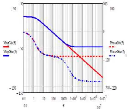
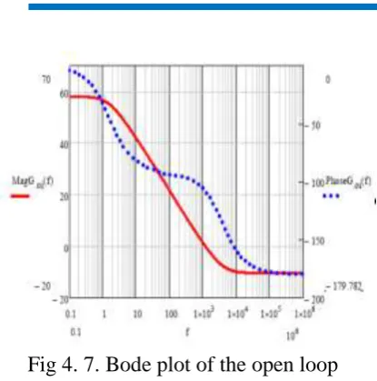
Fig. 6 presents a comparison between the frequency response of system transfer function 𝐺𝑖 (𝑠), and digitalized plant 𝐺𝑖 (𝑤). It is noticeable that the frequency response presents conformity up to 3 𝑘𝐻𝑧, when the phase error goes by substantial caused by the zero added because of the digitalization process.
Fig 4. 7. Bode plot of the open loop current transfer function.
The output current behavior of the grid-tied four-leg inverter can be described by (25). It can be seen that the output current only depends on the reference current. In other
words, under the feed-forward
compensation, the converter system is equivalent to an independent current source as viewed by the AC system.
For digital implementation of the control system in the z-domain, the controller of (20) is discretized by the bilinear transform with a sampling time of 𝑇𝑠 that is also the switching period [24]. Therefore, the controller transfer function (𝑧) can be expressed as (26):
The current reference, 𝑖𝑎𝑐𝑡𝑖𝑣𝑒,𝑐 , is used to inject the active power delivered from the wind through the inverter. The waveform of the active current reference is defined from
the fundamental component of the
measured load voltage, 𝑣𝑝𝑐𝑐,𝑐 𝑓 , configuring sinusoidal current. Therefore, the active current is a pure sinusoidal current, in phase with the fundamental component of the instantaneous load voltage. Dimensioning of the DC-link voltage controller is determined by the transfer function between the defined current reference and the DC-link voltage. From power balance of the inverter terminal, we have:
where 𝑖𝑐𝑎𝑝𝑎𝑐𝑖𝑡𝑜𝑟 is the DC-link capacitor current and 3/2 factor comes from the average ac power flow using peak values and 𝑣𝑝𝑐𝑐,𝑎𝑏𝑐𝑓 represents the fundamental component of the PCC voltage.
From (28) the current through the capacitor is:
The same current in terms of voltage across the capacitor is given by:
From (29) and (30) the differential equation for the DC-link voltage becomes:
control loop is shown in Fig. 8. The DC-link voltage
controller 𝐶𝑣𝑑𝑐 (𝑠) is multiplied by −1 to compensate for the negative sign of DC bus voltage dynamics. We will select the bandwidth of DC voltage loop to be less than two orders of magnitude smaller than that of the current loop.
Fig. 8. Block diagram of the DC voltage control loop.
Therefore, the closed current loop can be assumed ideal for design purposes and replaced by unity. The transfer functions of DC-link voltage control scheme, 𝐺𝑣𝑑𝑐 (𝑠), is presented in (32). The open loop transfer functions of the DC voltage control loop,
𝐺𝑜𝑣𝑑𝑐 (𝑠), is presented in (33) with 𝐶𝑣 (𝑠)
the controller of the DC voltage control loop, consisting of a Proportional Integral (PI) compensator as in (34), where the parameters of 𝑘𝑝 and 𝑘𝑖 are the proportional and integral gains of the compensator, respectively.
For DSP implementation of the DC-link voltage control scheme, 𝐺𝑣𝑑𝑐 (𝑠), is converted from continuous plane “𝑠” to the discrete plane “𝓏” in (35). To allow the use of frequency response method design, the conversion of 𝐺𝑣𝑑𝑐 (𝓏) transfer function from “𝓏” plane to “𝑤” plane in (36) is performed, using the bilinear transform of (23).
CONCLUSION
This paper addressed a
comprehensive control method for a back-to-back wind turbine system connected to an industrial plant. The control uses the four-leg inverter at the grid side to supply available active power from the wind
turbine system along with full
compensation of load current disturbances. The main contribution is based on CPT to impress the set-point reference and impose disturbances mitigation, which adds significant flexibility to the control structure. The control structure was tested
with a comprehensive real-time
benchmarking case-study with hardware in the loop. The control algorithms were compiled inside our TI DSP and validated using the real-time system “Opal-RT”. The algorithms were debugged and are ready for experimental validation in a retrofitting of a wind turbine (future work). The results showed good performance of the algorithm and the THD was improved for all different
operation conditions. The results support the system presented here which can avoid installation of active filter hardware by the utility or by the industrial consumer.
REFERENCES
[1] “Global Wind Report Annual Market Update 2013,” 2013. [Online]. Available: http://www.gwec.net.
[2] S. Li, T. A. Haskew, R. P. Swatloski, and W. Gathings, “Optimal and Direct-Current Vector Control of Direct-Driven
PMSG Wind Turbines,” IEEE Trans.
Power Electron., vol. 27, no. 5, pp. 2325– 2337, 2012.
[3] N. Angela, M. Liserre, R. A. Mastromauro, and A. D. Aquila, “A Survey of Control Issues in PMSG-Based,” IEEE Trans. Ind. Informatics, vol. 9, no. 3, pp. 1211–1221, 2013.
[4] J. Lagorse, M. G. Simões, and A. Miraoui, “A Multiagent Fuzzy-Logic-Based Energy Management of Hybrid Systems,” IEEE Trans. Ind. Appl., vol. 45, no. 6, pp. 2123–2129, 2009.
[5] X. Tan, Q. Li, and H. Wang, “Advances and Trends of Energy Storage Technology in Microgrid,” Int. J. Electr. Power Energy Syst., vol. 44, pp. 179–191, Jan. 2013.
[6] P. F. Ribeiro, B. K. Johnson, M. L. Crow, A. Arsoy, and Y. Liu, “Energy Storage Systems for Advanced Power Applications,” Proc. IEEE, vol. 89, no. 12, pp. 1744–1756, 2001.
[8] A. Chauhan and R. P. Saini, “A Review on Integrated Renewable Energy System Based Power Generation for Stand-alone Applications: Configurations, Storage
Options, Sizing Methodologies and
Control,” Renew. Sustain. Energy Rev., vol. 38, pp. 99–120, Oct. 2014.
[9] C. N. Bhende, S. Mishra, and S. G. Malla, “Permanent Magnet Synchronous Generator-Based Standalone Wind Energy Supply System,” IEEE Trans. Sustain. Energy, vol. 2, no. 4, pp. 361–373, 2011.
[10] H. Akagi, E. H. Watanabe, and M. Aredes, Instantaneous Power Theory and Applications to Power Conditioning. 2007.
[11] P. Tenti, H. K. M. Paredes, and P. Mattavelli, “Conservative power theory, a framework to approach control and accountability issues in smart microgrids,” IEEE Trans. Power Electron., vol. 26, no. 3, pp. 664–673, 2011.
[12] A. Mortezaei, M. G. Simoes, and F. P. Marafao, “Cooperative Operation Based Master-Slave in Islanded Microgrid with CPT Current Decomposition,” in Proc. IEEE PES, Denver, Colorado, USA, 2015, pp. 1–5.
G.Sunil is pursuing his Master of Technology in Power Electronics & Power
Electrical Drives, EEE Department,
VEMU, Kothakota, and Andhra Pradesh, India.
C. MD. Shareef completed his Post Graduation in Electrical Power Systems specialization From QUBA College of Engineering and Technology in 2012. He is presently working as Assistant Professor in the Department of Electrical & Electronics
Engineering at VEMU Institute of