A Proximity-Fed Antenna for Dual-Band GPS Receiver
Nu Pham1, Jae-Young Chung1, *, and Byungje Lee2
Abstract—A new design of band L1/L2 GPS antenna is proposed. The antenna generates
dual-band circularly polarized radiation by exciting a cross-slot and ring-slot of a concentric circular aperture using a proximity-coupled feed. Parametric studies show that the matching and axial ratio bandwidth of L1 (1.575 GHz) and L2 (1.227 GHz) bands can be independently tuned by alternating the ring radius and slot length. The range of frequency ratio and 3 dB center frequency can be highly adjusted by slot’s parameters. The size of the antenna is 73 mm×73 mm×6.4 mm including the ground, corresponding to 0.29λ×0.29λ×0.026λ at 1.227 GHz.
1. INTRODUCTION
Global Navigation Satellite System (GNSS) unfolds many practical applications in military, government service, and commercial use. In modern GNSS, a more accurate positioning is available by featuring multi-band operation highly immune to multipath interference [1]. For example, the Global Positioning System (GPS) utilizes two L-band frequencies: L1 (1.575 GHz) and L2 (1.227 GHz).
To take advantage of dual-band operation, a dual-band antenna with circularly polarized (CP) wave radiation is needed. The CP radiation can be generated by exciting an antenna with two orthogonal linearly polarized modes with a 90◦ phase difference. It can be implemented using a single- or dual-feeding structure. For the latter, the antenna feed network is rather large and complex due to the use of 90◦ hybrids or Wilkinson power dividers in the structure [2–5]. On the contrary, a single-feed antenna produces CP by wave-mode perturbation by implementing slots [6], stub-loads [7, 8], truncated corners [9] in the antenna geometry, or designing of vacant-quarter ring for bowtie dipole [10]. Thus, no external feeding network is required, and this is suitable for low-profile, lightweight, and low-cost antenna design.
A popular method to design a single-feed dual band antenna is stacking up two resonating structures with different sizes to generate two fundamental modes in each band of antenna [11]. A certain height between resonators is optimized to ensure impedance matching and bandwidth of antenna. Instead of using stacked antenna structure, the single patch with perturbations is exploited to generate a fundamental mode and a higher order mode for dual-band operation [12]. For GPS applications, T-shaped slits structure at the edge of patch antenna is proposed to excite TM10and TM30modes at GPS L1/L2 band [13]. The size of the antenna is 100 mm × 100 mm × 5.6 mm including the ground plane In [14], two concentric annular slots are used to produce CP at GPS L1/L2 bands with the antenna size of 100 mm × 100 mm × 15.6 mm. The relatively large height is due to the cavity installed in front of the patch radiator. The antenna in [15] employs an asymmetric S-shaped slot together with an aperture-coupled feed to generate dual-band CP radiation. Such non-contacting feeding method is known to offer an increase in antenna bandwidth and ease in fabrication. Moreover, independent tuning of radiating layer and feeding layer is available, which is a strong benefit, especially for a dual-band
Received 20 November 2015, Accepted 16 December 2015, Scheduled 23 December 2015
* Corresponding author: Jae-Young Chung (jychung@seoultech.ac.kr).
proximity-fed antenna has the benefit of reducing the level of spurious radiation when compared with antenna fed by aperture-coupled method. This feature offers stable antenna matching condition and radiation pattern when installed on a metal platform. The antenna radiator employs a circular patch with a cross-slot and ring-slot to generate TM11 mode at L1 and L2 bands with reduced antenna footprint. The overall size of antenna fabricated on FR-4 substrate is 73 mm × 73 mm × 6.4 mm including the ground, which corresponds to 0.29λ × 0.29λ × 0.026λ at 1.227 GHz. In Section 2, the antenna design and CP radiation mechanism are described in detail. Section 3 demonstrates the antenna tenability based on parametric studies. In Section 4, measurement results with a fabricated prototype are presented and compared with the simulation results.
2. ANTENNA DESIGN AND CP RADIATION
Figure 1 shows the antenna geometry. It is implemented in a double-layer substrate where the ground occupies the bottom layer, with circular radiator at the top, and the orthogonal feed in the middle, as depicted in Fig. 1(b). For the feed, a 50 Ω microstrip line of widthWf splits into two lines with a length difference ofl3 to induce quadrature phase difference. In addition, the two feed ends are arranged with 90◦ angular separation to excite the fundamental TM11 mode in an orthogonal manner.
The radiator at the top consists of an inner circular patch with radiusR1 responsible for L1 band resonance. As demonstrated in the next section, the L1 band impedance can be effectively tuned by the cross-slot length S1. For the L2 band resonance, an annular ring of width D is located on the circumference of the circular patch with a separation of W = R2 −R1. It is also found that the L2 band impedance can be effectively tuned byDand W. Note that adding this ring hardly affects the L1 band impedance, but affects the axial ratio (AR) of L1 band. For instance, the 3 dB AR bandwidth of L1 is wider asW increases. The size of cross- and ring-slots affects the antenna matching condition as the electromagnetic fields coupled to these slots can be represented by a series capacitor. The level of mutual coupling between cross- and ring-slot is mainly affected by the distance between them [16].
The initial size of circular patch radiusR1is determined by the fundamental TM11mode resonance frequency as follows [17]:
f1 = 1.84118×c
π×R1× √εr, (1)
where c is the speed of light, εr the dielectric constant of the substrate, and f1 corresponds to the L1 band center frequency (1.575 GHz). The outer ring radius R2 is related to the mean circumference of
W2
S1
l3
l4
Ws
Wf
R2
Po
L
W
R1
D
x y
P1
l2
W1 W2
l1
z
h1 Patch
Feed
Ground
h2 t
y
(a) (b)
(a) (b)
(c) (d)
Figure 2. Current distribution in the L2 band
with phase: (a) 0◦, (b) 45◦, (c) 90◦, (d) 135◦.
(a) (b)
(c) (d)
Figure 3. Current distribution in the L1 band
with phase: (a) 0◦, (b) 45◦, (c) 90◦, (d) 135◦.
the ring-slot and can be determined by equation [18]:
f2= c
π×(R1+R2) ×
1 +εr 2εr
1/2
, (2)
wheref2 corresponds to the L2 band center frequency (1.227 GHz). In addition, the ground sizeL×L can be determined as the patch antenna manner by [19]:
L= 2R1+ 6 (h1+h2), (3)
whereh1 and h2 are the are the substrate height between the patch and feed, and the feed and ground, respectively (See Fig. 1(b)). The initial values of the above parameters are calculated based on the properties of a FR-4 (εr= 4.4, tan δ= 0.02) with givenh1= 1.6 andh2 = 4.8 mm. Starting from these initial values, the antenna geometry is optimized to have smaller footprint L < 80 mm and to ensure antenna gain >1.5 dB.
Besides, the proposed antenna exploits asymmetry in the ring-slot to enhance the CP performance. As can be seen in the inset of Fig. 1(a), a pair of notches in the horizontal axis is applied to elongate the current path and split the fundamental mode into two orthogonal degenerate modes. These notches turn out to improve both the antenna matching and AR, especially at L2 band. The width and length of the notches are set to W1 −W2 = W and l1 −l2 = W/2, respectively, in that the overall length becomes 2l1+W1 = 0.2R1 similar to the asymmetric notches length reported [18, 20].
impacts on the antenna’s dual-band operation.
3.1. Patch and Ring Size
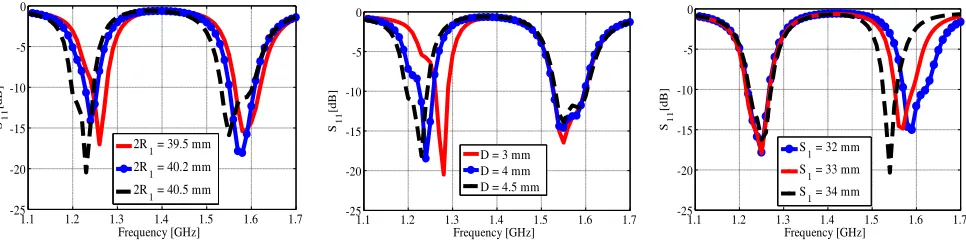
Figure 4 shows the reflection coefficients (S11) by varying the inner circular patch diameter 2R1. It is observed that the resonance frequencies of both L1 and L2 bands are decreased as R1 increases. More specifically, the resonance frequencies of L1 and L2 bands shift down from 1.59 to 1.56 GHz and from 1.23 to 1.21 GHz as 2R1 increases from 38 to 41 mm. At the same time, although not included, the minimum AR frequencies of L1 and L2 band shift the same amount due to the extension of current paths.
Next, the effect on S11 by varying D, the width of the outer ring, is investigated. Fig. 5 shows that altering D affects only L2 band resonance frequency. As D increases from 3 to 4.5 mm, the L2 resonance frequency shifts from 1.28 to 1.23 GHz while keeping the L1 band resonance frequency unchanged. Based on this, the optimization strategy can be deducted as identifying 2R1 that satisfies the L1 band matching condition, and then adjusting D to fine tune L2. It is worth noting that the ring-slot width W is fixed to 1 mm during the parametric study considering the 3 dB AR bandwidth at L1 as mentioned in the previous section.
3.2. Cross-Slot Length
In contrast to D affecting only L2 band, cross-slot length S1 has influence on only L1 band without changing L2 band matching condition. Fig. 6 showsS11 data by varyingS1. The increase ofS1 from 32 to 34 mm results in L1 resonance frequency to shift downward from 1.59 to 1.56 GHz, implying that the circular patch can be miniaturized by increasing the cross-slot length. The expense is the L1 bandwidth. As depicted,S11<−10 dB bandwidth is reduced from 49 MHz to 27 MHz by increasing S1.
Figure 7(a) shows the change in AR by varying S1. The AR minimum frequency at L1 decreases asS1 increases, but the 3 dB AR bandwidth remains the same. A closer look is provided in Figs. 7(b) and (c) using the Smith chart. The highlighted loci in the Smith chart refer to the impedance from 1.56 to 1.6 GHz for L1 and from 1.21 to 1.24 GHz for L2. It can be seen that the slight change in S1 from 33 mm to 33.5 mm rotates the locus of L1 without changing the shape of pigtail, resulting in the same AR bandwidth. Indeed, the Smith chart is considerably used during the antenna optimization process to predict not only the impedance matching condition but also the minimum AR center frequency and 3 dB AR bandwidth. Note that a variation in the cross-slot width Ws deforms the overall shape of pigtail in the Smith chart, thus altering both the L1/L2 matching and AR conditions. Ws is fixed to 2 mm in this parametric study.
1.1 1.2 1.3 1.4 1.5 1.6 1.7 -25
-20 -15 -10 -5 0
Frequency [GHz] S11
[d
B
]
2R1 = 39.5 mm 2R
1 = 40.2 mm
2R
1 = 40.5 mm
Figure 4. Reflection coefficients
by varying inner patch diameter 2R1.
1.1 1.2 1.3 1.4 1.5 1.6 1.7 -25
-20 -15 -10 -5 0
Frequency [GHz] S11
[d
B
]
D = 3 mm D = 4 mm D = 4.5 mm
Figure 5. Reflection coefficients
by varying outer ring width D.
1.1 1.2 1.3 1.4 1.5 1.6 1.7 -25
-20 -15 -10 -5 0
Frequency [GHz] S11
[d
B
]
S
1 = 32 mm
S1 = 33 mm S1 = 34 mm
Figure 6. Reflection coefficients
1.1 1.2 1.3 1.4 1.5 1.6 1.7 0
1 2 3 4 5 6
Frequency [GHz]
AR
[
d
B]
1.57
1.58
0.
2
1.
0
5.
0
+j1.0
-j1.0
0.0 0.
2
1.
0
5.
0
+j1.0
-j1.0 0.0
L1
L1
1.58 GHz
1.57 GHz
(a) (b) (c)
S
1 = 33 mm
S
1 = 33.5 mm
∞ ∞
Figure 7. Simulation results of axial ratio in dB and impedance in the Smith chart: (a) Axial ratio by
varyingS1, (b) Smith chart when S1 = 33 mm, and (c) Smith chart whenS1= 33.5 mm.
65 70 75 80 85
0 0.5 1 1.5 2 2.5 3
Ga
in
[
d
B]
Ground size [mm]
Gain L2 band Gain L1 band
Figure 8. Gain simulation with ground size. Figure 9. A picture of fabricated antenna.
3.3. Ground Plane Size
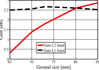
Figure 8 shows the effect of ground plane size L on the antenna gain. As shown, L highly affects the gain of L2 band but not L1. More specifically, the L2 gain increases from 0.35 to 2.85 dB as Lextends from 65 mm to 85 mm, while the L1 gain remains around 2.5 dB with a slight fluctuation of 0.25 dB. The ground plane size is also an important parameter for the front-to-back (F/B) ratio. Simulation results show that the F/B ratio increases asLincreases, and is higher than 10 dB in both L1/L2 bands when L > 70 mm. Considering the antenna gain to be more than 1.5 dB and F/B ratio > 10 dB, we choseL= 73 mm in the final design, which is 0.29λ at L2 band frequency (1.227 GHz).
4. ANTENNA MEASUREMENT
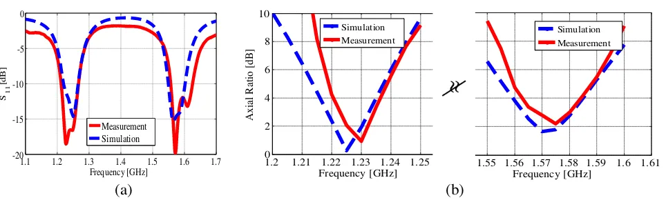
The antenna is fabricated in regard to the optimized parameters. Table 1 summarizes the optimized parameters and Fig. 9 shows the fabricated antenna mounted in an anechoic chamber ready for testing. Figs. 10(a) and (b) show the measured S11 and AR, respectively, together with the simulation results. Overall good agreements can be observed except for lower S11 values in the measured data, possibly due to higher material loss in the fabricated antenna. The measured S11 < −10 dB bandwidths are 6.1% (1.554–1.615 GHz) and 3.7% (1.216–1.261 GHz) for L1 and L2 bands, respectively. The measured 3 dB AR at the center frequency of L1 and L2 are 2.1 and 1.5 dB with the 3 dB AR bandwidths around 1%. Fig. 11 displays the radiation patterns at the center frequencies of L1 and L2 bands in thexz- and yz-planes (see the coordinate conventions in Fig. 1).
1.2 1.21 1.22 1.23 1.24 1.25 1.26 0 2 4 6 Frequency [GHz] Ax ial R at io [ d B]
1.54 1.55 1.56 1.57 1.58 1.590 1.6 1.61
2 4 6
Frequency [GHz]
1.1 1.2 1.3 1.4 1.5 1.6 1.7 -20 -15 -10 Frequency [GHz] S11 [d B ] Measurement Simulation (a) (b)
Figure 10. Measured results: (a) Reflection coefficient and (b) axial ratio.
10 dB 0 dB -10 dB -20 dB 0° 60° 90° 120° 150° 180° 240° 270° 300°
330° 10 dB
0 dB -10 dB -20 dB 30° 210° 10 dB 0 dB -10 dB -20 dB 10 dB 0 dB -10 dB -20 dB 10 dB 0 dB -10 dB -20 dB 0° 60° 90° 120° 150° 180° 240° 270° 300°
330° 10 dB
0 dB -10 dB -20 dB 30° 210° 10 dB 0 dB -10 dB -20 dB 10 dB 0 dB -10 dB -20 dB 0° 60° 90° 120° 150° 180° 240° 270° 300°
330° 10 dB
0 dB -10 dB -20 dB 30° 210° 10 dB 0 dB -10 dB -20 dB 10 dB 0 dB -10 dB -20 dB 10 dB 0 dB -10 dB -20 dB 10 dB 0 dB -10 dB -20 dB 0° 60° 90° 120° 150° 180° 240° 270° 300°
330° 10 dB
0 dB -10 dB -20 dB 30° 210° RH-meas LH-meas LH-sim RH-sim
(a) (b) (c) (d)
Figure 11. Measured and simulated radiation patterns: (a) 1.227 GHz in the xz-plane, (b) 1.575 GHz
in thexz-plane, (c) 1.227 GHz in the yz-plane, and (d) 1.575 GHz in theyz-plane.
Table 1. Optimized antenna parameters (mm).
Parameter S1 S2 Ws R1 D L Wf Pf
Value 33 32.5 2 38 5.7 73 3 11
Table 2. Comparison of key GPS antenna parameters.
Antenna structure
Antenna size (mm3)
3 dB AR beamwidth (◦)
S11<−10 dB bandwidths (%)
3 dB AR bandwidths (%)
RHCP gain (dBic)
L1 L2 L1 L2 L1 L2
Ref. [11] 90×90×135 – 10.64 8.82 4.3 4.5 4.5 4.5
Ref. [13] – – 0.0013 0.0016 0.0013 0.0016 – –
Ref. [14] 100×100×15.6 100◦ 3.7 1.2 0.9 0.6 1.45 1.1
Ref. [15] 115×115×21.52 – 12.5 16 0.6 6.9 5 5
-1500 -100 -50 0 50 100 150 2
4 6 8 10 12
Theta [deg.]
Ax
ia
l r
a
ti
o
[
d
B]
-1500 -100 -50 0 50 100 150 3
6 9 12
Theta [deg.]
Ax
ia
l r
a
ti
o
[
d
B]
(a) (b)
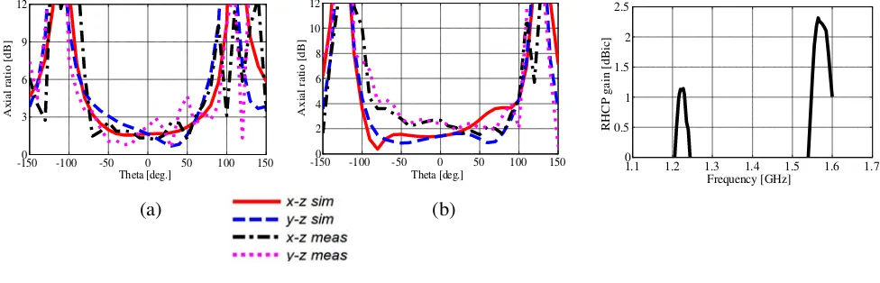
Figure 12. Axial ratio versus elevation (theta) angle: (a)
1.227 GHz and (b) 1.575 GHz.
1.1 1.2 1.3 1.4 1.5 1.6 1.7 0
0.5 1 1.5 2 2.5
Frequency [GHz]
RHCP g
a
in
[
d
Bic
]
Figure 13. Antenna measured
RHCP gain.
may result from the imperfection during the fabrication, for example, slight misalignments or air gaps between the asymmetric feed and patch layers. In addition, a small fault of cross-slot size can affect L1 band performances as well as 3 dB AR beamwidth. Fig. 13 shows the measured RHCP gain along the frequency range from 1.1 GHz to 1.7 GHz. The gain at L1 and L2 bands are 2.22 and 1.14 dBic, respectively, 0.5 dB lower than the simulation results in Fig. 8, which may be due to the imperfection in fabricated prototype.
5. CONCLUSION
A dual-band circularly polarized GPS antenna incorporating a simple proximity-coupled feed is designed and characterized. The proposed design consists of a circular patch and annular ring to excite the fundamental TM11 mode in both bands. It also employs a cross- and ring-slot to miniaturize the antenna footprint and lower the overall height of the antenna. The antenna design process was derived by calculating initial values of key geometric parameters based on simple closed-form equations, and then further optimized using a full-wave simulation tool. Parametric studies showed that the antenna had several key parameters to adjust the L1 and L2 band performance simultaneously or independently, making the antenna highly tunable. The measured results with a fabricated prototype showed a good agreement with the simulation results. After all, the proposed antenna is suitable for a low-profile installation of dual-band GNSS antenna, which requires a small frequency ratio in the range of 1.2– 1.36. Table 2 shows the comparison of key GPS antenna parameters among this work and previously reported ones. We note that the proposed design can be regarded as a good candidate of dual-band GPS antenna despite of its small footprint
Owing to the proximity-coupled feeding structure and slot mode operation, along with the suitable size of ground, the antenna can be placed in another metal platform as ground plane of arbitrary size without concerning the change in matching and CP performance. For CP antennas with a coaxial probe feed or other non-contacting feeds, the antenna’s impedance and AR tend to vary with the size of ground plane due to the resonant cavity mode formed between the ground and radiator.
ACKNOWLEDGMENT
Edition, Ganga-Jamuna Press, Lincoln, MA, 2010.
2. Pozar, D. M. and S. M. Duffy, “A dual-band circularly polarized aperture-coupled stacked microstrip antenna for global positioning satellite,” IEEE Trans. Antennas Propagat., Vol. 45, 1618–1625, November 1997.
3. Yohandri, J. T. S. Sumantyo, and H. Kuze, “A new triple proximity-fed circularly polarized microstrip antenna,”AEU-Int. J. Electron. C, Vol. 66, 395–400, May 2012.
4. Sun, X., Z. Zhang, and Z. Feng, “Dual-band circularly polarized stacked annular-ring patch antenna for GPS application,” IEEE Antenna Wirel. Propag. Lett., Vol. 10, 49–52, 2011.
5. Zhang, Y.-Q., X. Li, L. Yang, and S.-X. Gong, “Dual-band circularly polarized antenna with low wide-angle axial-ratio for tri-band GPS applications,” Progress In Electromagnetics Research C, Vol. 32, 167–179, 2012.
6. Hsieh, G. B., M. H. Chen, and K. L. Wong, “Single-feed dual-band circularly polarised microstrip antenna,” Electron. Lett., 1170–1171, 1998.
7. Heidari, A. A., M. Heyrani, and M. Nakhkash, “A dual-band circularly polarized stub loaded microstrip patch antenna for GPS applications,” Progress In Electromagnetics Research, Vol. 92, 195–208, 2009.
8. Liao, W. and Q.-X. Chu, “Dual-band circularly polarized microstrip antenna with small frequency ratio,” Progress In Electromagnetics Research Letters, Vol. 15, 145–152, 2010.
9. Su, C. M. and K. L. Wong, “A dual-band GPS microstrip antenna,” Microwave and Optical Technology Letters, 238–240, 2002.
10. Tran, H. H., S. X. Ta, and I. Park, “Single-feed, wideband, circularly polarized, crossed bowtie dipole antenna for global navigation satellite systems,” J. Electromagn. Eng. Sci., Vol. 14, No. 3, 299–305, September 2014.
11. Wang, Y., J. Feng, J. Cui, and X. Yang, “A dual-band circularly polarized stacked microstrip antenna with single-fed for GPS applications,”Antenna Propag. and EM Theory, 108–110, 2008. 12. Yang, K. P. and K. L. Wong, “Dual-band circularly-polarized square microstrip antenna” IEEE
Trans. Antennas Propagat., Vol. 49, 377–382, 2001.
13. Fujimoto, T., D. Ayukawa, K. Iwanaga, and M. Taguchi, “Dual-band circularly-polarized microstrip antenna for GPS application,”IEEE Antennas and Propagat. Society International Symposium, 1– 4, 2008.
14. Hsieh, W. T., T. H. Chang, and J. F. Kiang, “Dual-band circularly-polarized cavity-backed annular slot antenna for GPS receiver,” IEEE Trans. Antennas Propagat., Vol. 60, 2076–2080, 2012. 15. Chen, Z. N. and X. Qing, “Dual-band circularly polarized S-shaped slotted patch antenna with a
small frequency-ratio,” IEEE Trans. Antennas Propagat., Vol. 58, 2112–2115, 2010.
16. Morabito, A. F., T. Isernia, and L. Di Donato, “Optimal synthesis of phase-only reconfigurable linear sparse arrays having uniform-amplitude excitations,”Progress In Electromagnetics Research, Vol. 124, 405–423, 2012.
17. Balanis, C. A., “Microstrip antennas,” Antenna Theory Analysis and Design, 3rd Edition, 846, A John Wiley, 2005.
18. Wong, K. L., C. C. Huang, and W. S. Chen, “Printed ring slot antenna for circular polarization,” IEEE Trans. Antennas Propagat., Vol. 50, 75–77, 2002.
19. Subramanian, G. H. and S. S. Prabhu, “Design, analysis and fabrication of 2×1 rectangular patch antenna for wireless applications,” Int. J. Adv. Res. Electron. Comm. Eng., Vol. 4, March 2015. 20. Wu, J., X. Ren, Z. Li, and Y.-Z. Yin, “Modified square slot antennas for broadband circular