Available online: https://edupediapublications.org/journals/index.php/IJR/ P a g e | 1956
Design of S.I Engine Piston and Thermal Analysis with
Different Materials by Usign Fea
M.Diwakar, & Y.Suresh Kumar 1M.TECH SCHOLAR,
2Assistant professor,Dept of Mechanical Engineering, Nova College of Engineering &Technology,
Jangareddigudem,East Godavari(Dt) , A.P, India.
ABSTRACT
The project MODELLING AND
ANALYSIS OF PISTON in S.I engine
according to the forces acting on it
from the gases, which are released
during the combustion. The piston
head acts as a particular case and
hence the piston is analyzed for the
stresses
developed
due
to
the
conditions.
At first, the piston is designed
according to the specifications. After
the designing, the model is subjected
to certain conditions. Mainly piston is
connected to connecting rod and that
connecting rod is engaged to crank
shaft. According to the conditions we
have checked the stresses acting on it
and checked analysis of the model.
After the analyzing the changes are
done to the model if required.
In the analysis a model of piston of
the s.i engine is generated using
software CATIA, the analysis of the
piston is generated using Ansys. It
will takes thermal analysis on piston
with different materials and find the
heat flux. The result are calculated
and tabulated below and the heat flux
acting on the body are shown using
with different materials (aluminum
alloy and aluminum oxide (composite
material)).
INTRODUCTION:
The
internal combustion engine
is
an engine in which the combustion of
Available online: https://edupediapublications.org/journals/index.php/IJR/ P a g e | 1957
with an oxidizer (usually air) in a
combustion chamber that is an
integral part of the working fluid flow
circuit. In an internal combustion
engine (ICE) the expansion of the
high-temperature and high-pressure
gases produced by combustion apply
direct force to some component of the
engine. The force is applied typically
to pistons, turbine blades, or a nozzle.
This
force
moves
the
component
over
a
distance,
transforming chemical energy into
useful mechanical energy. The first
commercially
successful
internal
combustion engine was created by
Étienne Lenoir.
SOME
TYPES
OF
I.C
ENGINES PISTONS
A piston is a component of reciprocating
engines, reciprocating pumps, gas compressors and pneumatic cylinders, among other similar mechanisms. It is the moving component that is contained by a cylinder and is made gas-tight by piston rings. In an engine, its purpose is to transfer force from expanding gas in the cylinder to the crankshaft via a piston rod and/or connecting rod. In a pump, the function is reversed and force is transferred from the crankshaft to the piston for the purpose of compressing or ejecting the fluid in the cylinder. In some engines, the piston also acts as a valve by covering and uncovering ports in the cylinder wall.
Available online: https://edupediapublications.org/journals/index.php/IJR/ P a g e | 1958 Internal combustion engine piston, sectioned
to show the gudgeon pin.
An internal combustion engine is acted upon by the pressure of the expanding combustion gases in the combustion chamber space at the top of the cylinder. This force then acts downwards through the connecting rod and onto the crankshaft. The connecting rod is attached to the piston by a swivellinggudgeon pin (US: wrist pin). This pin is mounted within the piston: unlike the steam engine, there is no piston rod or crosshead (except big two stroke engines).
The pin itself is of hardened steel and is fixed in the piston, but free to move in the connecting rod. A few designs use a 'fully floating' design that is loose in both components. All pins must be prevented from moving sideways and the ends of the pin digging into the cylinder wall, usually by circlips.
Gas sealing is achieved by the use of piston rings. These are a number of narrow iron rings, fitted loosely into grooves in the piston, just below the crown. The rings are split at a point in the rim, allowing them to press against the cylinder with a light spring pressure. Two types of ring are used: the
upper rings have solid faces and provide gas sealing; lower rings have narrow edges and a U-shaped profile, to act as oil scrapers. There are many proprietary and detail design features associated with piston rings.
Pistons are cast from aluminum alloys. For better strength and fatigue life, some racing pistons may be forged instead. Early pistons were of cast iron, but there were obvious benefits for engine balancing if a lighter alloy could be used. To produce pistons that could survive engine combustion temperatures, it was necessary to develop new alloys such as Y alloy and Hiduminium, specifically for use as pistons.
A few early gas engines, had double-acting cylinders, but otherwise effectively all internal combustion engine pistons are single-acting. During World War II, the US submarine Pompano[note 2] was fitted with a prototype of the infamously unreliable H.O.R. double-acting two-stroke diesel engine. Although compact, for use in a cramped submarine, this design of engine was not repeated.
Trunk pistons
Trunk pistons are long relative to their diameter. They act both as a piston and cylindrical crosshead. As the connecting rod is angled for much of its rotation, there is also a side force that reacts along the side of the piston against the cylinder wall. A longer piston helps to support this.
Available online: https://edupediapublications.org/journals/index.php/IJR/ P a g e | 1959 now adopted the lighter weight slipper
piston.
A characteristic of most trunk pistons, particularly for diesel engines, is that they have a groove for an oil ring below the gudgeon pin, in addition to the rings between the gudgeon pin and crown.
The name 'trunk piston' derives from the 'trunk engine', an early design of marine steam engine. To make these more compact, they avoided the steam engine's usual piston rod with separate crosshead and were instead the first engine design to place the gudgeon pin directly within the piston. Otherwise these trunk engine pistons bore little resemblance to the trunk piston; they were extremely large diameter and double-acting. Their 'trunk' was a narrow cylinder mounted in the centre of the piston.
Crosshead pistons
Large slow-speed Diesel engines may require additional support for the side forces on the piston. These engines typically use crosshead pistons. The main piston has a large piston rod extending downwards from the piston to what is effectively a second smaller-diameter piston. The main piston is responsible for gas sealing and carries the piston rings. The smaller piston is purely a mechanical guide. It runs within a small cylinder as a trunk guide and also carries the gudgeon pin.
Because of the additional weight of these pistons, they are not used for high-speed engines.
Slipper pistons
Slipper piston
A slipper piston is a piston for a petrol
engine that has been reduced in size and weight as much as possible. In the extreme case, they are reduced to the piston crown, support for the piston rings, and just enough of the piston skirt remaining to leave two lands so as to stop the piston rocking in the bore. The sides of the piston skirt around the gudgeon pin are reduced away from the cylinder wall. The purpose is mostly to reduce the reciprocating mass, thus making it easier to balance the engine and so permit high speeds. A secondary benefit may be some reduction in friction with the cylinder wall, since the area of the skirt, which slides up and down in the cylinder is reduced by half. However most friction is due to the piston rings, which are the parts which actually fit the tightest in the bore and the bearing surfaces of the wrist pin, the benefit is reduced.
Available online: https://edupediapublications.org/journals/index.php/IJR/ P a g e | 1960 Two-stroke deflector piston
Deflector pistons are used in two-stroke engines with crankcase compression, where the gas flow within the cylinder must be carefully directed in order to provide efficient scavenging. With cross scavenging, the transfer (inlet to the cylinder) and exhaust ports are on directly facing sides of the cylinder wall. To prevent the incoming mixture passing straight across from one port to the other, the piston has a raised rib on its crown. This is intended to deflect the incoming mixture upwards, around the combustion chamber. Much effort, and many different designs of piston crown, went into developing improved scavenging. The crowns developed from a simple rib to a large asymmetric bulge, usually with a steep face on the inlet side and a gentle curve on the exhaust. Despite this, cross scavenging was never as effective as hoped. Most engines today use Schnuerle porting instead. This places a pair of transfer ports in the sides of the cylinder and encourages gas flow to rotate around a vertical axis, rather than a horizontal axis.
Piston
and
Piston
Rings
A piston is a cylindrical engine component
that slides back and forth in the cylinder bore by forces produced during the combustion process. The piston acts as a movable end of the combustion chamber. The stationary end of the combustion chamber is the cylinder head. Pistons are commonly made of a cast aluminum alloy for excellent and lightweight thermal conductivity. Thermal conductivity is the ability of a material to conduct and transfer heat. Aluminum expands when heated, and proper clearance must be provided to maintain free piston movement in the cylinder bore. Insufficient clearance can cause the piston to seize in the cylinder. Excessive clearance can cause a loss of compression and an increase in piston noise.
Piston features include the piston head, piston pin bore, piston pin, skirt, ring grooves, ring lands, and piston rings. The
piston head is the top surface (closest to the
cylinder head) of the piston which is subjected to tremendous forces and heat during normal engine operation.
A piston pin bore is a through hole in the
side of the piston perpendicular to piston travel that receives the piston pin. A piston pin is a hollow shaft that connects the small end of the connecting rod to the piston. The
skirt of a piston is the portion of the piston
Available online: https://edupediapublications.org/journals/index.php/IJR/ P a g e | 1961
A ring groove is a recessed area located
around the perimeter of the piston that is used to retain a piston ring. Ring lands are the two parallel surfaces of the ring groove which function as the sealing surface for the piston ring. A piston ring is an expandable split ring used to provide a seal between the piston an the cylinder wall. Piston rings are commonly made from cast iron. Cast iron retains the integrity of its original shape under heat, load, and other dynamic forces. Piston rings seal the combustion chamber, conduct heat from the piston to the cylinder wall, and return oil to the crankcase. Piston ring size and configuration vary depending on engine design and cylinder material.
Piston rings commonly used on small engines include the compression ring, wiper ring, and oil ring. A compression ring is the piston ring located in the ring groove closest to the piston head.
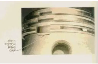
Figure 5 - Piston Ring Gap
Piston rings seal the combustion chamber, transferring heat to the cylinder wall and controlling oil consumption. A piston ring seals the combustion chamber through inherent and applied pressure. Inherent
pressure is the internal spring force that expands a piston ring based on the design and properties of the material used. Inherent pressure requires a significant force needed to compress a piston ring to a smaller diameter. Inherent pressure is determined by the uncompressed or free piston ring gap. Free piston ring gap is the distance between the two ends of a piston ring in an uncompressed state. Typically, the greater the free piston ring gap, the more force the piston ring applies when compressed in the cylinder bore. .
Dimensions of the piston
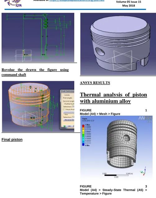
Available online: https://edupediapublications.org/journals/index.php/IJR/ P a g e | 1962 Rovolue the drawn the figure using
command shaft
Final piston
ANSYS RESULTS
Thermal analysis of piston
with aluminium alloy
FIGURE 1
Model (A4) > Mesh > Figure
FIGURE 3
Available online: https://edupediapublications.org/journals/index.php/IJR/ P a g e | 1963
Temperature
Total Heat Flux
2
ndmaterial aluminium oxide
Total Heat Flux > Figure
RESULTS
MATERIALS TOTAL HEAT
FLUX
ALUMINIUM
ALLOY
3.14e7
ALUMINIUM
OXIDE
7.1e6
Conclusion:
Available online: https://edupediapublications.org/journals/index.php/IJR/ P a g e | 1964 According the two materials al oxide is the
better heat absorber and less time to take cooling also, better material in thermal conditions.
REFERENCES
[1] Sunday Aribo, Joseph
AjibadeOmotoyinbo, Davies
OladayoFolorunso, ―High temperature mechanical properties of silicon carbide particulate reinforced cast aluminum alloy composite, Metallurgical and Materials Engineerings,Vol 18, pp. 9-16, 2011.
[2] Gopinath C.V, ―Finite Element Analysis of Reverse Engineered Internal Combustion Engine Piston‖ , AIJSTPME, Vol 2, pp. 85-92, 2011.
[3] EkremBuyukkaya, MuhammetCerit, ―Mechanical characterization of Aluminium silicon carbide composite‖, International journal of applied engineering research, Volume 1, pp. 4-9, 2007.
[4] Khurmi, Pandya and Shah, ―Design of machine Elements‖, S Chand, 14th edition, 2006.
[5]. T.T.Mon, M.M.Noor, K.Kadirgama, R A.BakarandM.F.Ramli, Finite Element Analysis on Thermal Effect of the Vehicle Engine,Proceedings of MUCEET:
Malaysian Technical Universities Conference on Engineering and Technology, 2009
[6]. I O Toppo, CFD Analysis of combustion characteristics of Jathropha in
compression ignition engine,Indian Institute
of Science, Bangalore
V.Srinivas, , M.TECH SCHOLAR : , Dept of Mechanical Engineering,
Nova College of Engineering & Technology, Jangareddigudem, East Godavari(Dt) , A.P, India.