Available Online at www.ijcsmc.com
International Journal of Computer Science and Mobile Computing
A Monthly Journal of Computer Science and Information Technology
ISSN 2320–088X
IJCSMC, Vol. 4, Issue. 11, November 2015, pg.57 – 63
RESEARCH ARTICLE
Design and Simulation of a Solar
Based DC-DC Converter for
Hybrid Electric Vehicles
Sandu Sridevi
1, P. Varaprasad Reddy
21M.Tech Student (PE&D), Vignana Bharathi Institute of Technology, Hyderabad
Email: [email protected]
2Assistant Professor, EEE Dept., Vignana Bharathi Institute of Technology, Hyderabad
Email: [email protected]
Abstract--This paper presents modeling, design and analysis of a bidirectional half-bridge DC/DC converter suitable for power electronic interface between the main energy system and the electric traction drive in hybrid electric vehicles. A solar based renewable energy system is considered as input. A parallel dc-linked multi input converter with a half-bridge bidirectional DC/DC cell topology is chosen to link the solar energy system with the dc-link. The paper focuses on modeling the proposed converter for steady state analysis. Averaging and linearization techniques are applied to obtain the averaged state space models and small signal models of the converter in both boost and buck operation modes. A criterion for sizing the converter passive components based on the imposed design specifications and constraints is illustrated. Simulation results of the buck-boost converter during normal functioning are presented. The same compared with the performance of DC-DC converter for the input of hybrid energy storage system which consists of battery and ultra-capacitor.
Keywords: Bidirectional DC/DC converter; hybrid electric vehicles; dynamic modeling; state space representation; solar cell, components sizing; design; simulation
1. INTRODUCTION
In order to determine the dc-link voltage and the energy storage unit capacity at the DC/DC converter terminals, it is empirical to specify the vehicle hybridization level. A full HEV is chosen with large traction motor, high-capacity energy storage pack and main DC bus voltage around 200-300V.
B. Choice of Hybrid Drivetrain Configuration
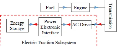
A parallel hybrid drive train rather than a series one is chosen for several reasons. As shown in Fig.1, the vehicle can be driven by the ICE alone, the EM alone or both engines at the same time utilizing the best performance of each. Unlike series hybrids, parallel hybrids require less number of energy conversion stages and feature less power demands on the electrical system which makes parallel hybrids less expensive and more energy efficient.
Fig. 1. Parallel hybrid drivetrain configuration
C. Choice of Electric AC Drive System
The AC drive is a classic Permanent Magnet Synchronous Motor (PMSM) drive which consists of a PMSM, a three-phase bridge voltage source inverter and a power electronic controller. Voltage source inverters are commonly used in HEV applications, where the source delivers a stiff voltage PMSMs exhibit higher efficiency, higher power density and high torque-to-inertia ratio when compared to induction motors. These advantages as well as the fast torque response make PMSMs good candidate for use in HEVs. The main disadvantage is the use of permanent magnets which are not only expensive but also sensitive to load and temperature.
3. DC-DC CONVERTER WITH HYBRID ENERGY STORAGE SYSTEM
A. Choice of Hybrid Energy Storage System
HEVs rely on the capability of their ESSs not only to store large amounts of energy but also to discharge according to load demand. A high power, high energy, and high efficiency ESS can be obtained by utilizing a hybrid battery /UC combination. The UC will increase the ESS power handling capability and reserve the amount of regenerative energy dissipated in the friction brakes due to the low power handling capability of the battery. The UC is used during transient pea k power demands and to capture regenerative energy which greatly reduces the voltage variations and stresses across the battery terminals and releases the burden of power converter interfacing the battery.
B. Choice of Power Electronics Interface Configuration
Fig. 2. Electric drive subsystem
4. DC-DC CONVERTER WITH SOLAR INPUT
A. PV array Characteristics
The use of single diode equivalent electric circuit makes it possible to model the characteristics of a PV cell. The mathematical model of a photovoltaic cell can be developed using MATLAB simulink toolbox. The basic equation from the theory of semiconductors that mathematically describes the I-V characteristic of the Ideal photovoltaic cell is given by
I = Ipvcell-Id (1)
Where,
Id = I0cell[exp(qv/αkT)-1] (2)
Therefore
I = Ipvcell- I0cell[exp(qv/αkT)-1] (3)
Where, „IPVCell‟ is the current generated by the incident light (it is directly proportional to the Sun irradiation), Id is the diode
equation, Io, cell‟ is the reverse saturation or leakage current of the diode, „q‟ is the electron charge [1.60217646* 10−19C], k is the Boltzmann constant [1.3806503 *10−23J/K], „T‟ is the temperature of the p-n junction, and „a‟ is the diode ideality
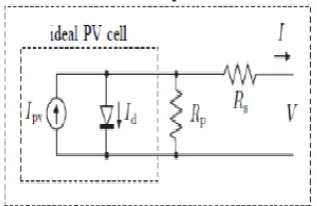
constant. Fig.3 shows the equivalent circuit of ideal PV cell.
Fig.3 Equivalent circuit of ideal PV cell
Practical arrays are composed of several connected PV cells and the observation of the characteristics at the terminals of the PV array requires the inclusion of additional parameters (as shown in Fig.8) to the basic equation:
I = Ipv-Io[exp(V+IRs/Vtα)-1]-(V+IRs/Rp) (4)
Where Vt = NskT/q is the thermal voltage of the array with „Ns‟ cells are connected in series. Cells connected in parallel increases the current and cells connected in series provide greater output voltages. V and I are the terminal voltage and current. The equivalent circuit of ideal PV cell with the series resistance (Rs) and parallel resistance (Rp) is shown in Fig.4.
Fig.4 Equivalent circuit of ideal PV cell with Rp and Rs.
Fig.5 I-V and P-V characteristics of PV cell
5. DC-DC CONVERTER CIRCUIT AND OPERATION
Dynamic modeling of power converter is necessary in order to study its transient behavior and analyze how variations in the input voltage, load current, and duty cycle affect its output voltage [3]-[15]. However, a switching power converter is a nonlinear time-varying system which is difficult to analyze due to its intrinsic large signal nature. Small signal modeling is a commonly used approach to simplify the analysis, control and design of the converter nonlinear system by transforming it into a linear time-invariant system. This is usually done by taking the average value of the state variables over one switching period and is known as state space averaged modeling which enables analyzing the system dynamic behavior. The converter state space equations are used to derive the small signal averaged equations and the system transfer functions which are further used in the design of the controllers to regulate the system performance. Fig. 4 shows the switching power converter model. The converter state variables are the capacitors voltages, vCin and vCo, and inductor current, iL. The input variables are
the load current, io, and the input source voltage, vin for battery or UC. The output variable is the dc-link voltage, vo, for UC
fed converter and the source current, iin, for battery fed converter.
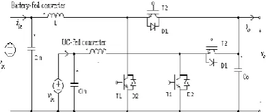
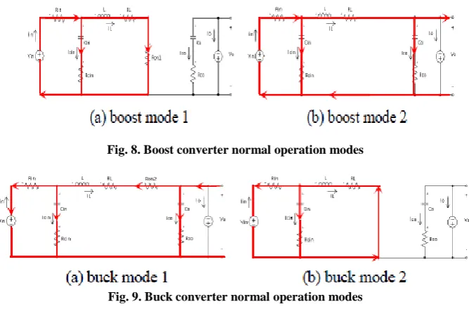
The half-bridge converter i s bidirectional in current; thus, it is analyzed once as a boost converter stepping up voltage from the battery/UC to the load side and then as a buck converter stepping down voltage from th e dc-link to the source. The half-bridge converter never operates in discontinuous conduction mode due to the fact that the power devices (T1 with D2 and T2 with D1) function in complementary modes and have bidirectional load and source. This fact reduces current peaks as well as stresses on passive and active components. Moreover, the half-bridge converter switches function pair-wise, meaning that when T1 is ON, T2 is OFF, and vice versa. If both transistors lead at the same time there is a SC and risk of destroying components. Th us, the converter always operate in continuous conduction mod e with only two switching states for each of the boost and buck operations as shown in Table I.
Fig .6 Parallel dc-linked multi-input bidirectional DC/DC converter
Fig .7 Power Switching Converter Model
Fig. 8. Boost converter normal operation modes
Fig. 9. Buck converter normal operation modes
6. SIMULATION RESULTS
The simulation circuits of both systems and corresponding results are shown in the following figures.
Fig .10 Simulation of DC-DC Converter with Battery/UC Input
Fig .11 Simulation of DC-DC Converter with Solar Input
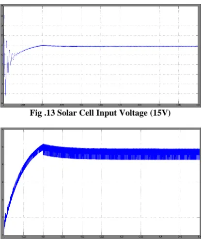
Fig .13 Solar Cell Input Voltage (15V)
Figure .14 Output Voltage of DC-DC Converter with Solar Input (50V o/p)
7. CONCLUSION
This paper presents design and analysis of a half bridge bidirectional DC/DC converter as a PEI between a HESS and the main DC bus in HEVs. We considered two different inputs for the proposed DC-DC converter: 1. Hybrid Battery/UC pack 2. Solar input. The performance of the DC-DC converter is analyzed for both the inputs. It is observed that the converter working efficiently for the solar input too. The converter components are sized based on the design requirements of a full HEV. To verify the converter operation, the proposed design is simulated using Matlab/Simulink.
REFERENCES
[1] H. Al-Sheikh, O. Bennouna, G. Hoblos, and N. Moubayed, “Study on power converters used in hybrid vehicles with monitoring and diagnostics techniques”, in Proc. IEEE MELECON 2014, in press.
[2] H. Al-Sheikh, O. Bennouna, G. Hoblos, and N. Moubayed, “Power electronics interface configurations for hybrid energy storage in hybrid electric vehicles”, in Proc. IEEE MELECON 2014, in press.
[3] A. Khaligh and Z. Li, “Battery, ultracapacitor, fuel cell, and hybrid energy storage systems for electric, hybrid electric, fuel cell, and plug-in hybrid electric vehicles: state of the art,” IEEE Trans. on Vehicular Technology, vol. 59, no. 6, pp. 2806-2814, 2010.
[4] L. Solero, A. Lidozzi, and J.A. Pomilio, “Design of multiple-input power converter for hybrid vehicles”, IEEE Trans. on Power Electronics, vol. 20, no. 5, pp. 1007-1016, Sept. 2005.
[5] A. Di Napoli, F. Crescimbini, F. G. Capponi, and L. Solero, “Control strategy for multiple input DC-DC power converters devoted to hybrid vehicle propulsion systems”, in Proc. IEEE ISIE 2002, vol. 3, pp. 1036-
1041.
[6] A. Lidozzi and L. Solero, “Power balance control of multiple-input DCDC converter for hybrid vehicles”, in Proc. IEEE ISIE 2004, vol. 2, pp. 1467-1472.
[7] A. Di Napoli, F. Crescimbini, S. Rodo, and L. Solero, “Multiple input DC-DC power converter for fuel-cell powered hybrid vehicles”, in Proc. IEEE PESC 2002, vol. 4, pp. 1685-1690.
[8] M. B. Camara, H. Gualous, F. Gustin, and A. Berthon, “Design and new control of DC/DC converters to share energy between supercapacitors and batteries in hybrid vehicles”, IEEE Trans. on Vehicular Technology, vol. 57, no. 5, pp. 2721-2735, 2008.
[10] M. Marchesoni and C. Vacca, “New DC–DC converter for energy storage system interfacing in fuel cell hybrid electric vehicles”, IEEE Trans. on Power Electronics, vol. 22, no. 1, pp. 301-308, Jan. 2007.
[11] A. Di Napoli, F. Crescimbini, L. Solero, and F. Caricchi, “Multiple input DC-DC power converter for power-flow management in hybrid vehicles” in Proc. IAS 2002, vol. 3, pp. 1578-1585.
[12] L.A. Tendillo, E.V. Idiarte, J.M. Altés, J.M. Moncusí, and H.V. Blaví, “Design and control of a bidirectional DC/DC converter for an Electric Vehicle”, EPE/PEMC 2012, pp. LS4d.2-1 - LS4d.2-5.
[13] A.J. Forsyth and S.V. Mollov, “Modelling and control of DC-DC converters”, Power Engineering Journal, vol. 12, no. 5, pp. 229-236, Oct. 1998.
[14] P. Pany, R.K. Singh, and R.K. Tripathi, “Bidirectional DC-DC converter fed drive for electric vehicle system”, International Journal of Engineering, Science and Technology, vol. 3, no. 3, pp. 101-110.
[15] W. Jianhua, Z. Fanghua, G. Chunying, and C. Ran, “Modeling and analysis of a buck/boost bidirectional converter with developed PWM switch model”, in Proc. IEEE ICPE & ECCE 2011, pp. 705-711.
Sandu Sridevi received B. Tech Degree in Electrical and Electronics Engineering from Sridevi Womens Engineering College(JNTUH) in the year of 2013. She is currently M. Tech student in the stream Power Electronic and Drives. Vignana Bharathi Institute of Technology, Hyderabad, India. And she is interested in the field of Power Electronics and Drives.
Email:[email protected]
P. Varaprasad Reddy is currently working as an Assistant Professor in Vignana Bharathi Institute of Technology, Hyderabad, India. His research areas include Power Electronic Drives and Renewable Energy Sources.