Implementation of Layer 3 Vpns over Layer 2 Vpn
Topologies Using Gns3 Software
S.Anuradha & T.Srinivasa Padmaja
1PG Student, Dept. of ECE, Sri Padmavathi Mahila University, Tirupati . 2Senior Assistant Professor, Dept. of ECE, Sri Padmavathi Mahila University, Tirupati .
1 [email protected]@gmail.com,2[email protected]
ABSTRACT:
To implement VPNs to connect geographically separated customer sites. VPNs were originally introduced to enable
service providers to use common physical infrastructure to implement emulated
point-to-point links between customer sites. A customer network implemented with any VPN technology would contain distinct regions under the customer's control called the customer sites connected to each other via the service provider network. The peer-to-peer model was developed to overcome the drawbacks of the Overlay model and provide customers with optimal data transport via the Service Provider backbone. Hence, the service provider would actively participate in customer Layer 3 routing. Customer Layer 3 routing information is carried between routers in the provider network and customer network. The peer-to-peer model, consequently, does not require the creation of virtual circuits. Layer 3
VPNs implemented on MPLS
backbone of service providers are referred as “MPLS L3 VPNs”.
I.INTRODUCTION:
Multiprotocol Label Switching
(MPLS) has evolved from being a buzzword
in the networking industry to a widely
deployed technology in service provider
(SP) networks. In recent years, MPLS has
also been adopted by the enterprise and
federal market segments. MPLS is a
contemporary solution to address a
multitude of problems faced by present-day
networks: speed, scalability, quality of
service (QoS) management, and traffic
engineering. Service providers are realizing
larger revenues by the implementation of
service models based on the flexibility and
value adds provided by MPLS solutions.
MPLS also provides an elegant solution to
service requirements for next-generation IP
based backbone networks.
II.LITERATURE SURVEY:
In traditional IP networks, routing
protocols are used to distribute Layer 3
routing information. The network
172.16.10.0/24 is propagated using an IP
routing protocol. Regardless of the routing
protocol, packet forwarding is based on the
destination address alone. Therefore, when a
packet is received by the router, it
determines the next-hop address using the
packet's destination IP address along with
the information from its own
forwarding/routing table. This process of
determining the next hop is repeated at each
hop (router) from the source to the
destination except in the case of
policy-based routing where a certain outbound
policy might affect packet forwarding.
III.PROPOSED METHOD: In MPLS
enabled networks, packets are forwarded
based on labels. These labels might
correspond to IP destination addresses or to
other parameters, such as QoS classes and
source address. Labels are generated per
router (and in some cases, per interface on a
router) and bear local significance to the
router generating them. Routers assign
labels to define paths called Label Switched
Paths (LSP) between endpoints. Because of
this, only the routers on the edge of the
MPLS network perform a routing lookup.
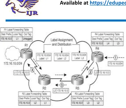
The routers in MPLS network R1, R2, and
R3 propagate updates for 172.16.10.0/24
network via an IGP routing protocol just like
in traditional IP networks, assuming no
filters or summarizations are not configured.
This leads to the creation of an IP
forwarding table. Also, because the links
connecting the routers are MPLS enabled,
they assign local labels for destination
172.16.10.0 and propagate them upstream to
their directly connected peers using a label
distribution protocol; for example, R1
assigns a local label L1 and propagates it to
the upstream neighbor R2. R2 and R3
similarly assign labels and propagate the
same to upstream neighbors R3 and R4,
respectively. Consequently, as illustrated in
Figure 1-2, the routers now maintain a label
forwarding table to enable labeled packet
forwarding in addition to the IP routing
table. The concept of upstream and
downstream is explained in greater detail in
Figure 1.1: Forwarding in the MPLS
Domain
As shown in Figure 1.1, the following
process takes place in the data forwarding
path from R4 to R1:
1. R4 receives a data packet for network
172.16.10.0 and identifies that the path to
the destination is MPLS enabled.
Therefore, R4 forwards the packet to
next-hop Router R3 after applying a label L3
(from downstream Router R3) on the
packet and forwards the labeled packet to
R3.
2. R3 receives the labeled packet with label
L3 and swaps the label L3 with L2 and
forwards the packet to R2.
3. R2 receives the labeled packet with label
L2 and swaps the label L2 with L1 and
forwards the packet to R1.
4. R1 is the border router between the IP and
MPLS domains; therefore, R1 removes the
labels on the data packet and forwards the
IP packet to destination network
172.16.10.0.
MPLS functionality on Cisco devices is
divided into two main architectural blocks:
1.Control plane – Performs functions
related to identifying reachability to
destination prefixes. Therefore, the
control plane contains all the Layer 3
routing information, as well as the
processes within, to exchange
reachability information for a
specific Layer 3 prefix. Common
examples of control plane functions
are routing protocol information
exchange like in OSPF and BGP.
Hence, IP routing information
exchange is a control plane function.
In addition, all protocol functions
that are responsible for the exchange
of labels between neighboring
routers function in the control plane
(explained in detail in section "LDP
Session Establishment").
2.Data plane – Performs the
functions relating to forwarding data
packets. These packets can be either
Layer 3 IP packets or labeled IP
packets. The information in the data
plane, such as label values, are
derived from the control plane.
A.MPLS TERMINOLOGY:
This section provides an overview of the
common MPLS-related terminology used :
o Forwarding Equivalence Class
(FEC) – As noted in RFC
3031(MPLS architecture), this group
of packets are forwarded in the same
manner (over the same path with the
same forwarding treatment).
o MPLS Label Switch Router (LSR) –
Performs the function of label
switching; the LSR receives a
labeled packet and swaps the label
with an outgoing label and forwards
the new labeled packet from the
appropriate interface. The LSR,
depending on its location in the
MPLS domain, can either perform
label disposition (removal, also
called pop), label imposition
(addition, also called push) or label
swapping (replacing the top label in
a label stack with a new outgoing
label value). The LSR, depending on
its location in the MPLS domain,
might also perform label stack
imposition or disposition. The
concept of a label stack is explained
later in this section. During label
swapping, the LSR replaces only
the top label in the label stack; the
other labels in the label stack are left
untouched during label swapping and
forwarding operation at the LSR.
o MPLS Edge-Label Switch Router
(E-LSR) – An LSR at the border of
an MPLS domain. The ingress Edge
LSR performs the functions of label
imposition (push) and forwarding of
a packet to destination through the
MPLS-enabled domain. The egress
Edge LSR performs the functions of
label disposition or removal (pop)
and forwarding an IP packet to the
destination. Note that the imposition
LSR might involve label stacks
versus only labels.
Figure 1.2: LSR and Edge LSR
o MPLS Label Switched Path (LSP) –
The path from source to destination
for a data packet through an
MPLS-enabled network. LSPs are
unidirectional in nature. The LSP is
usually derived from IGP routing
information but can diverge from the
IGP's preferred path to the
destination (as in MPLS traffic
engineering, which is discussed in
Chapter 9, "MPLS Traffic
Engineering"). In Figure 1-4, the
LSP for network 172.16.10.0/24
from R4 is R4-R3-R2-R1.
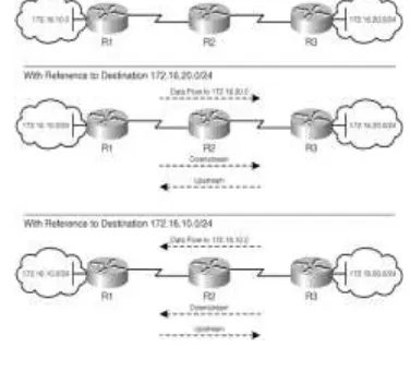
o Upstream and downstream – The
concept of downstream and upstream
are pivotal in understanding the
operation of label distribution
(control plane) and data forwarding
in an MPLS domain. Both
downstream and upstream are
defined with reference to the
destination network: prefix or FEC.
Data intended for a particular
destination network always flows
downstream. Updates (routing
protocol or label distribution,
LDP/TDP) pertaining to a specific
prefix are always propagated
upstream. This is depicted in Figure
1-5 where downstream with
reference to the destination prefix
172.16.20.0/24 is in the path
R1-R2-R3, and downstream with reference
to 172.16.10.0/24 is the path
R3-R2-R1. Therefore, in Figure 1-5, R2 is
downstream to R1 for destination
172.16.20.0/24, and R1 is
downstream to R2 for destination
Figure 1.3: Upstream and
Downstream
o MPLS labels and label stacks – An
MPLS label is a 20-bit number that
is assigned to a destination prefix on
a router that defines the properties of
the prefix as well as forwarding
mechanisms that will be performed
for a packet destined for the prefix.
A label stack is an ordered set of labels
where each label has a specific function. If
the router (Edge LSR) imposes more than
one label on a single IP packet, it leads to
what is called a label stack, where multiple
labels are imposed on a single IP packet.
Therefore, the bottom-of-stack indicator
identifies if the label that has been
encountered is the bottom label of the label
stack.
The TTL field performs the same function
as an IP TTL, where the packet is discarded
when the TTL of the packet is 0, which
prevents looping of unwanted packets in the
network. Whenever a labeled packet
traverses an LSR, the label TTL value is
decremented by 1.
The label is inserted between the Frame
Header and the Layer 3 Header in the
packet. Figure 1-7 depicts the label
imposition between the Layer 2 and Layer 3
headers in an IP packet.
Figure 1.4: MPLS Label Imposition
If the value of the S bit
(bottom-of-stack indicator) in the label is 0, the router
understands that a label stack
implementation is in use. As previously
mentioned, an LSR swaps only the top label
in a label stack. An egress Edge LSR,
however, continues label disposition in the
label stack until it finds that the value of the
S bit is set to 1, which denotes a bottom of
the bottom of the stack, it performs a route
lookup depending on the information in the
IP Layer 3 Header and appropriately
forwards the packet toward the destination.
In the case of an ingress Edge LSR, the
Edge LSR might impose (push) more than
one label to implement a label stack where
each label in the label stack has a specific
function.
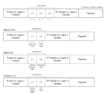
Label stacks are implemented when offering
MPLS-based services such as MPLS VPN
or MPLS traffic engineering. In MPLS VPN
(see Chapter 3, "Basic MPLS VPN
Overview and Configuration"), the second
label in the label stack identifies the VPN. In
traffic engineering (see Chapter 9), the top
label identifies the endpoint of the TE
tunnel, and the second label identifies the
destination. In Layer 2, VPN
implementations over MPLS, such as AToM
(see Chapter 11, "Any Transport over MPLS
[AToM]") and VPLS (see Chapter 12,
"Virtual Private LAN Service [VPLS]), the
top label identifies the Tunnel Header or
endpoint, and the second label identifies the
VC. All generic iterations of the label stack
implementation are shown in Figure 1-8.
Figure 1.5: MPLS Label Stack
B. MPLS CONTROL AND DATA
PLANE COMPONENTS:
Cisco Express Forwarding (CEF) is the
foundation on which MPLS and its services
operate on a Cisco router. Therefore, CEF is
a prerequisite to implement MPLS on all
Cisco platforms except traditional ATM
switches that support only data plane
functionality. CEF is a proprietary switching
mechanism used on Cisco routers that
enhances the simplicity and the IPv4
forwarding performance of a router
manifold.
The LIB functions in the control
plane and is used by the label distribution
protocol where IP destination prefixes in the
routing table are mapped to next-hop labels
neighbors, as well as local labels generated
by the label distribution protocol.
The LFIB resides in the data plane and
contains a local label to next-hop label
mapping along with the outgoing interface,
which is used to forward labeled packets.
Information about reachability to destination
networks from routing protocols is used to
populate the Routing Information Base
(RIB) or the routing table. The routing table,
in turn, provides information for the FIB.
The LIB is populated using information
from the label distribution protocol and from
the LIB along with information from the
FIB that is used to populate the LFIB.
IV. BASIC MPLS CONFIGURATION:
A. FRAME-MODE MPLS CONFIGURATION
AND VERIFICATION:
In frame mode, MPLS uses a 32-bit label
that is inserted between the Layer 2 and
Layer 3 headers. Layer 2 encapsulations like
HDLC, PPP, Frame Relay, and Ethernet are
frame-based except for ATM, which can
operate either in frame mode or cell mode.
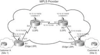
Basic Frame-Mode MPLS Overview,
Configuration, and Verification
Figure 2-1 shows a frame-based MPLS
provider network providing MPLS services
to sites belonging to Customer A. The
frame-based provider's network consists of
routers R1, R2, R3, and R4. R1 and R4
function as Edge Label Switch Routers
(LSRs) while R2 and R3 serve as LSRs.
Figure 1.6: Frame-Mode MPLS Provider
Network
V. PE-CE ROUNTING
PROTOCAL-STATIC AND RIP:
A. PE-CE ROUNTING PROTOCAL-STATIC
AND RIP:
Configuring MPLS VPNs is an
integral function in service provider
environments and enterprise networks.
Preceding chapters provided you with basic
concepts related to MPLS label distribution
and propagation, and MPLS VPN concepts
multiprotocol BGP, and label propagation in
VPN networks.
This follows as :
o Static PE-CE routing overview,
configuration, and verification
o RIPv2 PE-CE routing overview,
configuration, and verification
o RIPv1 PE-CE routing configuration
and verification
B.STATIC PE-CE CONFIGURATION, AND
VERIFICATION:
Static PE to CE routing is one of the most
common routing techniques used in MPLS
VPN deployments. Static PE-CE routing is
an optimal solution for sites either having a
single PE-CE connection or limited number
of subnets in the customer edge (CE)
network or both. Static PE to CE routing
also prevents the customer or the service
provider from intentionally or accidentally
flooding each other with false routing
information. The service provider therefore
retains control over customer routing. Static
PE-CE routing might increase the provider's
operational and administrative overheads to
maintain static routes. This is because static
PE-CE routing does not provide dynamic
rerouting and therefore requires additional
configuration for every new prefix on the PE
routers and possibly on the CE router in the
absence of a default route.
Static PE-CE routing involves the following:
On a CE router:
a.Configuring static routes to specific
remote CE networks in the same VPN or
b.Configuring a static default route
On a PE router:
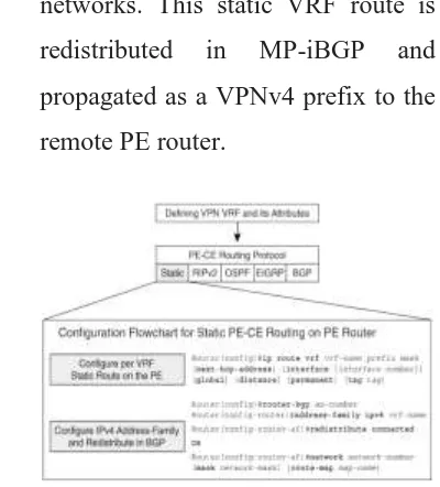
o Configuring a static VRF route to
reach the connected CE router's
networks. This static VRF route is
redistributed in MP-iBGP and
propagated as a VPNv4 prefix to the
remote PE router.
Figure 1.7: Configuration Flowchart
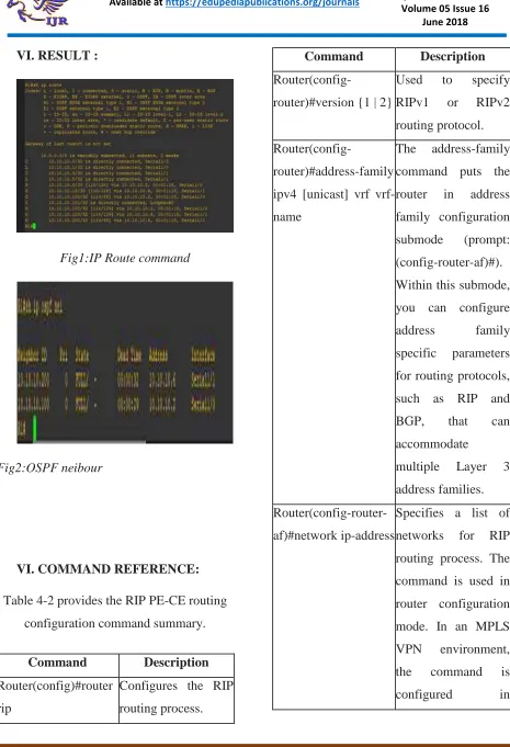
VI. RESULT :
Fig1:IP Route command
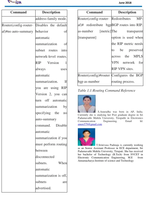
Fig2:OSPF neibour
VI. COMMAND REFERENCE:
Table 4-2 provides the RIP PE-CE routing
configuration command summary.
Command Description
Router(config)#router
rip
Configures the RIP
routing process.
Command Description
Router(config-router)#version {1 | 2}
Used to specify
RIPv1 or RIPv2
routing protocol.
Router(config-router)#address-family
ipv4 [unicast] vrf
vrf-name
The address-family
command puts the
router in address
family configuration
submode (prompt:
(config-router-af)#).
Within this submode,
you can configure
address family
specific parameters
for routing protocols,
such as RIP and
BGP, that can
accommodate
multiple Layer 3
address families.
Router(config-router-af)#network ip-address
Specifies a list of
networks for RIP
routing process. The
command is used in
router configuration
mode. In an MPLS
VPN environment,
the command is
Command Description
address-family mode.
Router(config-router-af)#no auto-summary
Disables the default
behavior of
automatic
summarization of
subnet routes into
network-level routes.
RIP Version 1
always uses
automatic
summarization. If
you are using RIP
Version 2, you can
turn off automatic
summarization by
specifying the no
auto-summary
command. Disable
automatic
summarization if you
must perform routing
between
disconnected
subnets. When
automatic
summarization is off,
subnets are
advertised.
Command Description
Router(config-router-af)# redistribute bgp
as-number [metric]
[transparent]
Redistributes
MP-BGP routes into RIP.
The transparent
option is used when
the RIP metric needs
to be preserved
across the MPLS
VPN network for
RIP VPN sites.
Router(config)#router
bgp as-number
Configures the BGP
routing process.
Table 1.1:Routing Command Reference
S.Anuradha was born in AP, India. Currently she is studying her Post graduate degree in Sri Padamavathi Mahila University, Tirupathi in Electronics
Communication Engineering. Email Id: