Available online: https://pen2print.org/index.php/ijr/ P a g e | 543
Fracture Analysis of Crack Propagation Using Different Materials on
Three Crack Modes of Failure
#1 J.SHARATH KUMAR P.G SCHOLAR
#2 B.PRAVEEN KUMAR ASSISTANT PROFESSOR
DEPARTMENT OF MECHANICAL ENGINEERING
TALLA PADMAVATHI COLLEGE OF ENGINEERING,SOMIDI,WARANGAL,T.S.
ABSTRACT
In this thesis, the fracture mechanics of crack propagation using different materials Titanium, Nickel Alloy 718, Glass Fiber Reinforced Polymer, Carbon Fiber Reinforced Polymer is investigated for three modes of failure in a rectangular block. Fracture, Static analyses are done on all the three modes of failure to determine displacements, stresses, stress intensity factors, and vibrations. 3D modeling is done in Creo 2.0 and analysis is done in Ansys.
I.INTRODUCTION
The field of mechanics which concerns with the cracks propagation in materials study is Fracture Mechanics. It utilizes strategies for analytical solid mechanics for calculating the force on a crack & those of solid mechanics experiments to describe the resistance of material's to fracture.
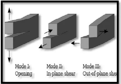
There are 3 ways of force applying enabling propagation of a crack:
● Mode I fracture – Opening mode
(a tensile stress normal to crack plane),
● Mode II fracture – Sliding mode (a shear
stress acting parallel to crack plane & perpendicular to the crack front), &
● Mode III fracture – Tearing mode (a
shear stress acting parallel to the plane of the crack and parallel to the crack front).
Fig 1:-Mode I, Mode II, and Mode III crack loading.
Fracture
A fracture is the detachment of a question or material into at least two pieces under the action of stress. The fracture of a solid more often than not happen because of the advancement of certain removal intermittence surfaces inside the solid.
II.LITERATURE SURVEY
Available online: https://pen2print.org/index.php/ijr/ P a g e | 544
M.Shohel[2], Three dimensional (3D) opening
mode stress intensity factors (SIFs) for auxiliary steel welded ‘T’ points of interest were explored by the limited component strategy. A 3D shape dependent revision factor is proposed for semi elliptical surface cracks. The viewpoint proportion (a/c) of a semi elliptical crack assumes a key job in the guess of 3D‐SIF qualities, and in the present investigation, it was evaluated for a 3D crack examination. The evaluated 3D‐SIF was resolved through a relationship between’s the a/c proportion and the two dimensional SIF for semi elliptical cracks in the thickness course adjoining the web flange intersection of a welded ‘T’.
3D MODELS OF DIFFERENT CRACK MODES
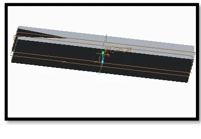
In this thesis, 3 models of different crack modes are done in Creo 2.0. A rectangular block of 100mm*50mm*3mm is taken.
Crack Mode I
In the mode I, the loading is done on the body by tensile forces, such that surfaces of crack are pulled apart in thickness direction. The 3D model of rectangular block with Crack mode I is shown in below figure.
Fig 2:- 3D model of Crack Mode I
Crack Mode II
In the mode II, the loading is done on the body by shear forces parallel to surfaces of crack. The 3D model of rectangular block with Crack mode II is shown in below figure.
Fig 3:- 3D model of Crack Mode II
Crack Mode III
In the mode III, the loading is done on the body by shear forces parallel to crack’s crack front. The 3D model of rectangular block with Crack mode II is shown in below figure.
Fig 4:- 3D model of Crack Mode III
III.ANALYSIS ON DIFFERENT CRACK MODES
The fracture mechanics of crack
propagation using different materials
Titanium, Nickel Alloy 718, Glass Fiber
Reinforced Polymer, Carbon Fiber
Reinforced Polymer is investigated for three modes of failure in a rectangular block.
FRACTURE ANALYSIS
Available online: https://pen2print.org/index.php/ijr/ P a g e | 545
GLASS FIBER REINFORCED POLYMER (GFRP)
CRACK MODE I
Fig 5:- Imported model of beam with crack mode I
Fig 6:-meshed model of beam with crack mode I
Select fracture tool
Fig 7:-Pre-meshed crack
Named Selection→ Crack→ Crack front, Select Crack Shape – Semi Elliptical, Enter major radius → 5 mm, Enter minor radius →2 mm, Enter Fracture affected zone Height – 13.55mm, Enter largest contour radius – 5 mm
Fig 8: - Crack on edge
Fig 9:- Load of 1400N is applied at crack tip
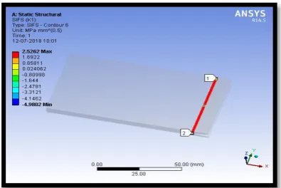
Available online: https://pen2print.org/index.php/ijr/ P a g e | 546 Fig 11:- J- integral of crack mode I by using
GFRP
CRACK MODE II
Fig 12:-Stress intensity factor of crack mode II by using GFRP
Fig 13:- J – Integral of crack mode II by using GFRP
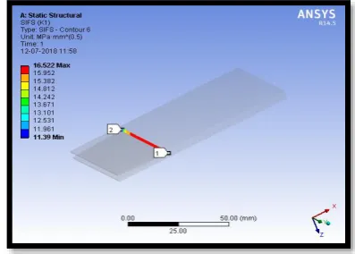
CRACK MODE III
Fig 14:- Stress intensity factor of crack mode III by using GFRP
Fig 15:-J- integral of crack mode III by using GFRP
IV.RESULTS & DISCUSSIONS FRACTURE ANALYSIS
The table below shows the stress intensity factors and J – Integral for 3 crack modes and different materials.
CRA CK MOD
E
MATERI AL
SIFS K1
(MPa.mm^ 0.5)
JINT
(mJ/mm
2)
I
TITANIU
M 2.7413
0.00104 3
NICKEL
718 2.5502
0.00055 147
GFRP 2.5262 0.00402
01
CFRP 2.5262 0.06968
Available online: https://pen2print.org/index.php/ijr/ P a g e | 547
II
TITANIU
M 3.3737
-0.00013
731
NICKEL 3.2485
-8.0691e
-5
GFRP 3.2335
-0.00059
855
CFRP 3.2335
-0.01037
5
III
TITANIU
M 17.031
-4.5185e
-5
NICKEL
718 16.579
-5.0582e
-5
GFRP 16.522
-0.00041
159
CFRP 16.522
-0.00713
43 From the above table, the following
observations can be made:
For Titanium material, the stress intensity factor is increasing for Crack Mode II by about 18% when compared with Crack Mode I. The stress intensity factor is increasing for Crack Mode III by about 85% when compared with Crack Mode I.
For Nickel 718 material, the stress intensity factor is increasing for Crack Mode II by about 21% when compared with Crack Mode I. The stress intensity factor is increasing for Crack Mode III by about 83.7% when compared with Crack Mode I.
For Glass Fiber Reinforced Polymer, the stress intensity factor is increasing for Crack Mode II by about 21 % when compared with Crack Mode I. The stress intensity factor is increasing for Crack Mode III by about 84% when compared with Crack Mode I. For Carbon Fiber Reinforced Polymer,
the stress intensity factor is increasing for Crack Mode II by about 22 %
when compared with Crack Mode I. The stress intensity factor is increasing for Crack Mode III by about 85% when compared with Crack Mode I.
STATIC STRUCTURAL ANALYSIS CRA CK MOD E MATER IAL Deform ation (mm) Stre ss (M Pa) Strain I TITANI UM 0.00879 9 18.9 26 0.0001 8555 NICKE L 0.00481 36 18.9 75 9.987e -5
GFRP 0.03525
9
18.9 79
0.0007 2998
CFRP 0.61116 18.9
79 0.0126 53 II TITANI UM 0.03230 6 13.5 49 0.0001 3284 NICKE L 0.01763 9 12.4 2 6.537e -5
GFRP 0.12917 12.2
63
0.0004 7166
CFRP 2.2389 12.2
63
0.0081 755
III
TITANI
UM 0.04581
18.9 34 0.0001 8563 NICKE L 0.02538 9 18.9 63 9.9807e -5
GFRP 0.18624 18.9
64
0.0007 294
CFRP 3.2282 18.9
64
0.0126 43 From the above table, the following
observations can be made:
For Titanium material, the stress is increasing for Crack Mode I by about 28% when compared with Crack Mode II. The stress is increasing for Crack Mode III by about 28.4% when compared with Crack Mode II. For Nickel 718 material, the stress is
increasing for Crack Mode I by about 34% when compared with Crack Mode II. The stress is increasing for Crack Mode III by about 34.5% when compared with Crack Mode II. For Glass Fiber Reinforced Polymer,
Available online: https://pen2print.org/index.php/ijr/ P a g e | 548 I by about 35.38% when compared
with Crack Mode II. The stress is increasing for Crack Mode III by about 35.33% when compared with Crack Mode II.
For Carbon Fiber Reinforced Polymer, the stress is increasing for Crack Mode I by about 35% when compared with Crack Mode II. The stress is increasing for Crack Mode III by about 35% when compared with Crack Mode II.
V.CONCLUSION
By observing fracture analysis results, the stress intensity factors are less for crack at mode I and when Polymers are used. The stress intensity factors are decreasing for crack at mode I by about 21.8% when compared with that of crack at mode II and by 84.7% when compared with that of crack at mode III when GFRP and CFRP are used. By observing static structural analysis results, the stress are less for crack at mode II and when Glass Fiber Reinforced Polymer is used. The stresses are decreasing for crack at mode II by about 54.76% when compared with that of crack at mode I and by 35.33% when compared with that of crack at mode III.
REFERENCES
1. M. D. Nikam, G. V. Patil, G. N.
Thokal, V. H. Khatawate, Estimation
of stress intensity factor (sif) on crack component by using finite element analysis, International Journal of Mechanical Engineering and Technology, Volume 5, Issue 1, January 2014.
2. M. Shohel, C. Menzemer, G.A.
Arthur, Estimation of
three‐dimensional stress intensity factor for structural ‘T’ details, Fatigue and fracture of engineering materials and structures, volume 39, issue 9, September 2016.
3. Djamila Benarbia, Mohamed
Benguediab, Determination of Stress Intensity Factor in Concrete Material Under Brazilian Disc and Three-Point
Bending Tests Using Finite Element Method, University of Sidi Bel Abbes, Sidi Bel Abbes , City BenMhidi. B.P. 89, Algeria, 03 September 2015.
4. J. C. Passieux, A. Gravouil, J.
R´ethor´e and M.C. Baietto, Direct estimation of generalized stress intensity factors using a three-scale concurrent multigrid X-FEM, International Journal for Numerical Methods in Engineering, 2011.
5. F. Khelil, M. Belhouari, A Numerical
Approach for the Determination of Mode I Stress Intensity Factors in PMMA Materials, Engineering, Technology & Applied Science Research Volume 4, Issue No. 3, 2014.
6. Abdelkader Boulenouar,
Noureddine Benseddiq, Fe Model
For Linear-Elastic Mixed Mode Loading: Estimation Of Sifs And Crack Propagation, Journal Of Theoretical And Applied Mechanics, 2014.
7. J.Caicedo and A.Portela, Direct
Computation Of Stress Intensity Factors In Finite Element Method,
European Journal Of Computational Mechanics, 10 July 2017.
8. M.L. HATTALI, H. AURADOU, M.
FRANCOIS, V. LAZARUS,
Numerical and experimental approaches for the determination of two-parameter fracture mechanics in wedge splitting loading, 21st Congress Francis the Technique, 2013.
9. Akash S. Ingle, S.J.Parihar,
Determination of Stress Intensity Factor for a crack in thin plate under Mode-I loading using Finite Element Analysis, International Journal of Innovative and Emerging Research in Engineering Volume 2, Issue 4, 2015.
10. Zhuang He, Andrei Kotousov,