R E S E A R C H
Open Access
Delay-tolerant distributed space-time
coding with feedback for cooperative MIMO
relaying systems
Tong Peng and Rodrigo C. de Lamare
*Abstract
An adaptive delay-tolerant distributed space-time coding (DSTC) scheme equipped with a feedback channel is proposed for two-hop cooperative multiple-input multiple-output (MIMO) networks. A maximum likelihood receiver and adjustable code matrices subject to a power constraint with a decode-and-forward cooperation strategy are considered with different DSTC antenna configurations. In the proposed delay-tolerant DSTC schemes, an adjustable code matrix is employed to transform the space-time coded matrices at the relay nodes. Stochastic gradient and least squares algorithms are also developed with reduced computational complexity. The proposed algorithms are then extended to a cooperative MIMO system using amplify-and-forward strategy and opportunistic relaying algorithms in order to develop a delay-tolerant coding scheme combined with optimal relay selection strategies. An upper bound on the pairwise error probability and a rank criterion analysis are derived which indicate the advantage of the
proposed algorithms. Simulation results show that the proposed algorithms obtain significant performance gains and address the delay issue in cooperative MIMO systems as compared to existing DSTC schemes.
Keywords: Adaptive algorithms, cooperative systems, delay-tolerant distributed space-time block codes
1 Introduction
Cooperative multiple-input multiple-output (MIMO) sys-tems can obtain diversity gains by providing copies of transmitted signals with the help of relays to improve the reliability of wireless communications [1–5] and in applications to spectrum sensing [6, 7]. The idea behind cooperative relaying systems is to employ multiple relay nodes between the source node and the destination node to form a distributed antenna array, which can provide significant advantages in terms of diversity gains. Sev-eral cooperation strategies that exploit the links between relay nodes and the destination node such as amplify-and-forward (AF), decode-amplify-and-forward (DF), compress-and-forward (CF) [1], and various distributed space-time coding (DSTC) schemes [2, 3, 8, 9] have been exten-sively studied in the literature. A key problem that arises in cooperative MIMO systems and which degrades the performance of such systems is the existence of delays
*Correspondence: [email protected]
Communications Research Group, Department of Electronics, University of York, York YO10 5DD, UK
between the signals that are space-time coded at the relays and decoded at the destination.
The deployment of distributed space-time coding (DSTC) schemes at relay nodes in a cooperative net-work can provide the system diversity and coding gains to mitigate the interference by adding more copies of the transmitted signals at the destination. However, a seri-ous issue for distributed MIMO systems using a DSTC scheme is the asynchronous transmission from the relays or the delayed reception of the DSTC scheme at the destination. The delayed code matrices and data for-warded from the relays shift the DSTC structure which results in the collapse of the rank design criterion and leads to degradation of decoding performance. In order to address the delay problem, various delay-tolerant dis-tributed space-time coding (DT-DSTC) schemes [10–14] have been recently reported for distributed MIMO sys-tems. Extending the distributed threaded algebraic space-time (TAST) codes [10], Damen and Hammons designed a delay-tolerant coding scheme in [11] by the extension of the Galois field employed in the coding scheme to achieve full diversity and full rate. A further optimization which
ensures that the codes in [11] obtain full diversity with the minimum length and lower decoding complexity has been presented in [12]. The authors of [13] have pro-posed delay-tolerant linear convolutional DSTC schemes which can maintain the full diversity property under any delay situation among the relays. In [14], a transmit pro-cessing technique based on linear constellation precoder (LCP) design has been employed to construct an opti-mal DT-DSTC scheme to achieve the upper bound on the error probability.
In the literature, two basic configurations of DSTC schemes have been reported: one in which the cod-ing is performed independently at the relays [15, 16], denoted multiple-antenna system (MAS) configuration, and another in which coding is performed across the relays [11, 14], called single-antenna system (SAS) con-figuration. The received symbol matrix at the destina-tion node in the MAS configuradestina-tion is a sum of fully encoded DSTC schemes from each relay node, while in the SAS configuration, the received symbol matrix con-tains only one DSTC scheme encoded across all the relays. Considering delays between the relay nodes, the sum of the DSTC schemes will be affected by imperfect asyn-chronous superposition of signals in the MAS configura-tion, while the structure of the received DSTC schemes in the SAS configuration will be switched. It is not clear the key advantages of these schemes and their suitabil-ity for situations with delays. In addition, the work on delay-tolerant DSTC has focused on encoding using a fixed scheme, such as TAST codes in [10], which are dif-ficult to implement with other DSTC schemes. In the literature, the DSTC designs in [17–23] can achieve full diversity order and high coding gains but are vulnerable to delays. In order to improve the existing DSTC schemes and overcome the delay issues, a general delay-tolerant encoding design and algorithm is needed. Moreover, the DT-DSTC schemes in the literature do not employ feed-back or optimal relay selection algorithms to improve the performance of the systems. The advantage of employing feedback to optimize DSTC schemes have been stud-ied in [16, 24] with various DSTC schemes. However, strategies to exploit feedback and improve the design of DT-DSTC schemes remain unexplored. Opportunistic cooperation algorithms are reported in [18] and [19]. The authors in [18] provide three relay selection algorithms for distributed systems which can achieve a lower bit error rate (BER) performance compared to the traditional equal power allocation schemes, and an opportunistic resource allocation optimization design which maximizes the delay-limited capacity and minimizes the outage prob-ability is given in [19]. However, the single-antenna relays are employed in the designs so that if a DSTC scheme is employed at the relay node, it will be severely affected after selecting the optimal relay or allocating the optimal
relay to the best position when delays are considered among the relays.
In this paper, we propose an adaptive delay-tolerant DSTC scheme and algorithms for cooperative MIMO relaying systems equipped with a feedback channel in both MAS and SAS scenarios. We first propose a delay-tolerant adjustable code matrices optimization (DT-ACMO) algorithm based on the maximum likelihood (ML) criterion subject to constraints on transmitted power at the relays for different cooperative systems. Unlike [10–14] which are assessed in the SAS scenario, the proposed algorithms are designed and investigated in both MAS and SAS scenarios. Specifically, adaptive optimization algorithms using stochastic gradient (SG) and recursive least square (RLS) estimation methods are developed for the DT-ACMO algorithm in order to release the destination from the high computational com-plexity of the optimization procedure. We study how the adjustable code matrices affect the DSTC scheme during the encoding process and how to optimize the adjustable code matrices by employing an ML detector. Then, we analyze the differences in terms of the rank criterion and pairwise error probabilities (PEP) of the DSTBC schemes in MAS and SAS configurations with the same number of antennas and delay profiles. We focus on how the different system configurations affect the delay tolerance of the DSTBC schemes. Moreover, we extend our design to cooperative systems exploiting the AF protocol and the opportunistic relaying algorithms in [18] in order to devise a delay-tolerant adjustable code matrices opportunistic relaying optimization (DT-ACMORO) algorithm which can address the delay issue when optimal power allocation and relay selection are employed. The proposed delay-tolerant designs can be implemented with different types of DSTC schemes in cooperative MIMO relaying systems with DF or AF protocols.
The paper is organized as follows. Section 2 describes the two-hop cooperative MIMO systems with multiple relays considered in this work, the DF strategy, and the DSTC configurations. In Section 3, the proposed DT-DSTC scheme and optimization algorithms for the adjustable code matrix are presented. The proposed DT-ACMO algorithm is extended to the AF protocol and combined with the opportunistic relaying algorithms in Section 4. The rank criterion and the PEP of the delayed DSTBC schemes employed in these two types of systems are analyzed in Section 5. The results of the simulations are given in Section 6. Section 7 gives the conclusions of the work.
Notation: the italic, the bold lowercase, and the bold uppercase letters denote scalars, vectors, and matrices, respectively. The operatorE[·] stands for expected value, and X F=
Tr(XH·X) = Tr(X·XH)is the Frobe-nius norm. Tr(·)stands for the trace of a matrix, and(·)† for pseudo-inverse. TheN×Nidentity matrix is written asIN.
2 Cooperative MIMO system model
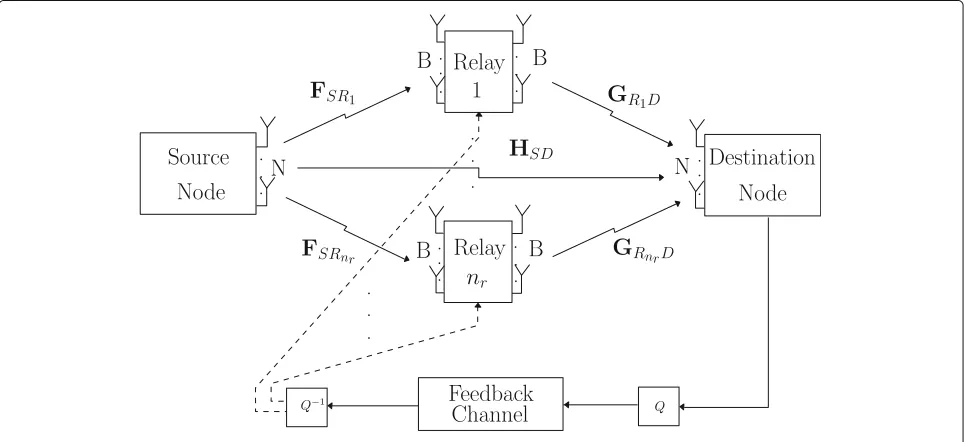
We consider a cooperative communication system, which consists of one source node,nrrelay nodes (Relay 1, Relay
2, ..., Relaynr), a feedback channel, and one destination
node as shown in Fig. 1. For simplicity, the source and the destination employN antennas and can either transmit or receive at one time even though the destination could employ more thanNantennas. The number of antennas at the relays is set toB. We consider two types of system configurations in this paper: one is the MAS configuration which employs relay nodes with B = N antennas, and another one is the SAS configuration which employs relay
nodes withB = 1 antenna. Other hybrid configurations might also be considered with an arbitrary distribution of antennas. As mentioned in the previous section, MAS obtains a sum of the fully encoded DSTC schemes at the destination and SAS obtains one full DSTC scheme at the destination. The diversity order of MAS and SAS with the same number of distributed antenna elements is the same; however, their delay tolerance is different as shown in Section 5. A delay profile which is given by =δ1,δ2, ...,δnr
, whereδk denotes the relative delay of
the signal received from thekth relay node as a reference to the earliest received relay signal. The maximum relative delay is denoted asδmax. Assumptions are considered as
follows:
1. 0≤δ1≤δ2≤...≤δmax.
2. The source and the relay nodes do not know the delay profile. However, the destination node knows
perfectly. In practice, a designer can setas an upper bound obtained by experimentation. 3. The destination node knows the channels between
the relays and the destination perfectly, and the relays know the channels between the source node and themselves perfectly.
4. The DSTC scheme used for the two system models is the same in order to provide a fair comparison. 5. The feedback channel is error-free and delay-free for
simplicity.
We consider only one user at the source node in our sys-tem that operates in a spatial multiplexing configuration. Lets[i] denotes the transmitted information symbol vec-tor at the source node, which contains N parameters,
s[i]=[s1[i] ,s2[i] ,. . .,sN[i] ], and has a covariance matrix
Es[i]sH[i]=σs2IN, whereσs2denotes the signal power.
The source node broadcastss[i] tonr relay nodes as well
as to the destination in the first hop. After the reception, each relay performs detection and subsequently encodes the data. Alternatively, the relays can employ cyclic redun-dancy check (CRC), which allows the relay node to know if the detection is successful, and automatic repeat request (ARQ) schemes.
By employing the DF protocol, the received symbols are re-encoded at each relay node prior to transmission to the destination node in the second hop. We first consider the
kth relay node in MAS which employs relays with mul-tiple antennas, and the N × 1 signal vectors[i] will be re-encoded by anN×T DSTC coding scheme, whereT
refers to the number of time slots. TheN×TDSTC coding scheme is multiplied by anN×Nadjustable code matrix k[i] generated randomly [15]. The relationship between
thekth relay and the destination is described by
RRkDMAS[i]=GRkDMAS[i]kMAS[i]MRkDMAS[i]+NRkD[i] , (1)
where GR
kDMAS[i] denotes the (δmax + T) × N delayed version of the channel matrix between thekth relay node and the destination node and MRkDMAS[i] is the N ×T DSTC scheme.NRkD[i] stands for the noise matrix at the destination with entries of additive white Gaussian noise (AWGN) with zero mean and variance σd2. The(δmax + T)×N received symbol matrixRRkDMAS[i] in (1) can be written as an N(δmax + T)× 1 vectorrRkDMAS[i] using equivalent channel and code matrices that is given by
rRkDMAS[i]=keqkMAS[i]GeqkMAS[i]˜s[i]+nRkD[i] , (2)
where theN(δmax+T)×NT delay profile matrixk =
[0δk×N;IN;0(δmax−δk)×N] at the kth relay nodes is
con-sidered. The block diagonalNT ×NT matrixeqkMAS[i] denotes the equivalent adjustable code matrix, and the
NT×NmatrixGeqkMAS[i] stands for the equivalent chan-nel matrix which is the combination of the DSTC scheme MRkDMAS[i] in (1) and the channel matrixGRkDMAS[i]. The N×1 vectors[˜i] stands for the data processed by the relay node with the DF protocol whereas theN(δmax+T)×1
vectornRkD[i] generated at the destination node contains noise samples.
The first hop in SAS is similar to that in MAS: the relays perform detection and encode the data symbols. The only difference between SAS and MAS is the DSTC encoding process. At thekth relay node in SAS, a 1×Ncode vector mk(s)is assigned which denotes thekth row in theN×N
DSTC scheme matrixMRkDSAS[i]. The DSTC code matrix will be multiplied by a 1×Nadjustable code vectorφk[i]
before the second hop. The signal matrix sent from the
kth relay node can be described as
RRkDSAS[i]=gRkDSAS[i](φkSAS[i]·MRkDSAS[i])+NRkD[i] , (3)
wheregR
kDSAS[i] denotes the(δmax+T)×1 delayed ver-sion of the channel vector between thekth relay node and the destination andNRkD[i] stands for the noise matrix whose samples have zero mean and variance σd2. The (δmax+T)×Nreceived symbol matrixRRkDSAS[i] in (3) can be expressed using equivalent matrices and rewritten as anN(δmax+T)×1 vectorrRkDSAS[i] given by
rRkDSAS[i]=kGeqkSAS[i]eqkSAS[i]s[˜i]+nRkD[i] , (4)
where the block diagonalN×NmatrixeqkSAS[i] denotes the diagonal equivalent adjustable code matrix and the block diagonal NT × N matrixGeqkSAS[i] stands for the equivalent channel matrix. TheN(δmax+T)×1
equiva-lent noise vectornRkD[i] generated at the destination node contains the noise parameters.
The use of an adjustable code matrix or a randomized matrixeqk[i] which achieves the full diversity order and provides a lower error probability has been studied in [15]. The uniform sphere randomized matrix which achieves the lowest BER of the analyzed schemes and contains ele-ments that are uniformly distributed on the surface of a complex hyper-sphere of radiusρis used in our system. The proposed adaptive algorithms detailed in the next section optimize the code matrices employed at the relay nodes in order to achieve a lower BER. At the destina-tion node, the adjustable code matrices are normalized and then transmitted back to the relay nodes so that no increase in the energy is introduced at the relay nodes and the comparison between different schemes is fair.
After rewriting the received vectors in (2) and (4), we can consider the received symbol vector at the destination node as an N(T +δmax+1)×1 vector. Therefore, the
received symbol vector for MAS and SAS can be written respectively as
rMAS[i]=
HSD[i]
nr
k=1keqkMAS[i]GeqkMAS[i]
˜
s[i]
+
nSD[i]
nRD[i]
=HMAS[i]s[˜i]+nD[i] ,
(5)
and
rSAS[i]=
HSD[i] nr
k=1kGeqkSAS[i]eqkSAS[i]
˜
s[i]
+
nSD[i]
nRD[i]
=HSAS[i]˜s[i]+nD[i] ,
(6)
where HSD[i] denotes the channel matrix between the
source and the destination and theN(δmax+T+1)×N
matrix of all the links in the network. We assume that the coefficients in all channel matrices are independent and remain constant over the transmission. TheN(δmax+ T +1)× N noise vectornD[i] contains the equivalent
received noise vector at the destination, which can be modeled as complex Gaussian random variables with zero mean and varianceσd2. The system considered here needs a feedback channel for transmitting the optimized code matrices and the information of the optimal relay node back to the relays. We have studied the effect of using a binary symmetric channel (BSC) as the feedback chan-nel in [16] and concluded that imperfect feedback chanchan-nel with different error probabilities and different numbers of bits in quantization lead to different detection errors in the optimized code matrices at the relays and also cause degradation of the BER performance at the destination.
3 Delay-tolerant adjustable code matrix optimization for delayed DSTC schemes
In this section, we propose a delay-tolerant adjustable code matrix optimization (DT-ACMO) strategy which employs an ML receiver at the destination for design-ing DSTC schemes in both MAS and SAS configurations. Adaptive RLS and SG algorithms [25] for determining the parameters of the adjustable code matrix with reduced computational complexity are also devised. The DSTC scheme encoded at each relay node employs an ML-based adjustable code matrix, which is computed at the desti-nation node and obtained by a feedback channel in order to process the data symbols prior to transmission to the destination. We assume that the functions used in the optimization problems in this section are continuously differentiable and the proof is given in Section 5. It is worth to mention that the code matrices will be sent back to the relays through a feedback channel after the opti-mization and they are only used at the relays so the direct link from the source node to the destination node is not considered for simplicity.
3.1 DT-ACMO algorithm for MAS
The ML criterion is employed for optimizing the adjustable code matrices and performing symbol detec-tion in the DT-ACMO algorithm, which is equivalent to a least squares (LS) criterion in this case. AnN×Dmatrix Sis stored at the destination which contains all the possi-ble combinations of the transmitted symbol vectors. The constrained ML optimization problem can be written as
the received symbol vector without noise which is deter-mined by substituting the dth column of S into (7) andeq
kMAS[i] denotes the N(δmax+ T) ×NT delayed adjustable code matrix at the kth relay node. As men-tioned in [16], the optimization algorithm contains a dis-crete part which refers to the ML detection and a continuous part which refers to the optimization of the adjustable code matrix. The detection and the optimization are implemented separately in this work. Joint detection and estimation procedures can benefit the optimization of the code and result in improved performance, but the com-putational complexity increases [26, 27]. As a result, other detectors such as MMSE [28, 29] and sphere decoders [30, 31] can be used in the detection part in order to reduce the computational complexity. The ML optimiza-tion problem for determining the transmitted symbol vector in (7) is given by
ˆ
wheresd stands for thedth column ofS. By substituting
each column inSinto (8) to search the most likely trans-mitted symbol vectorˆs[i] according to the ML detection, we can then calculate the optimal adjustable code matrix eqkMAS[i]. The Lagrangian expression of the optimization problem in (7) is given by
L =rMAS[i]−
and by taking the instantaneous gradient of L with respect to the code matrix
for the received vector without the desired code matrix. The optimal code matrix ˆeqk
∇L
eqkMAS[i]
∗ = 0 and the optimal adjustable code
matrix is given by
eqkMAS[i]=(rMAS[i]−rlMAS[i])ˆs
Note that the last term related to the power constraint in (9) is not considered during the optimization in (11) which is due to the high computational complexity of calculating the value ofγ. The power constraint can be achieved by the normalization procedure described by
We also note that the algorithm presented in (9)–(12) belongs to the class of stochastic gradient algorithms [32], which employ instantaneous values of the gradient. Therefore, the learning of the proposed approach suffers from noisy estimates and often exhibits some excess mean squared error in relation to the optimal MMSE solution.
3.1.1 RLS code matrix estimation algorithm
The RLS estimation algorithm for the code matrix
eqkMAS[i] is derived in this subsection. The superior con-vergence behavior of LS type algorithms when the size of the adjustable code matrix is large is the reason for its uti-lization. The computational complexity is reduced from cubic to square by employing the RLS algorithm.
In order to derive an RLS algorithm to compute
ˆ
whereλstands for the forgetting factor. By expanding the right-hand side of (13), taking the gradient with respect to
eqkMAS[i] ∗
and equating the terms to zero, we obtain
The power constraint is not considered in the derivation but is enforced by the normalization strategy after the optimization. We can define
[i]=
so that we can rewrite (14) as
eqkMAS[i]=Z[i]
−1[i] . (17)
By employing the matrix inversion lemma in [33], we can obtain stitute (16) and (18) into (17) to obtain the expression of the code matrix which is given by
As mentioned before, a normalization procedure after (19) is applied in order to maintain the energy of the relayed data. Table 1 shows a summary of the DT-ACMO RLS algorithm.
3.1.2 SG code matrix estimation algorithm
The SG estimation algorithm for the code matrix
eqkMAS[i] is derived in this section. As shown in (11), the inversion of the matrices is required and the computa-tional complexity will be increased by employing a large number of relay nodes or number of antennas.
∇L stands for the error vector. After we obtain (20), the pro-posed SG algorithm can be obtained by introducing a step size into a gradient optimization algorithm to update the result until the convergence is reached. The DT-ACMO SG algorithm is given by
eqkMAS[i+1]=
whereβdenotes the step size in the recursion.
The energy of transmitted data processed by the code matrices in (21) will be increased with the processing of the adaptive algorithm, which will contribute to the reduc-tion of the error probability. The normalizareduc-tion of the code matrix expressed in (12) is applied to ensure that the energy is not increased and for a fair comparison among the analyzed DSTC schemes. A summary of the DT-ACMO SG algorithm is given in Table 2.
3.2 DT-ACMO algorithm for SAS
The main difference of the DT-ACMO algorithm in SAS compared with that in MAS is the computational com-plexity which is related to the dimensions of the adjustable code matrices used at the relays. If we assume that the samples of the data received by the antennas used at the relays are independent and identically distributed (i.i.d) and consider the relay nodes as one unit transmitter, the
Table 1Summary of the DT-ACMO RLS algorithm
1: Initialize:P[0]=δ−1I
N(λmax+T)×N(λmax+T), Z[0]=IN(λmax+T)×N(λmax+T),
2: Generate[ 0] randomly with the power constraint Treqk MAS[i]Heqk MAS[i]
distributed array formed by the relays can be seen as one transmitter withnrantennas. The equivalent received
vector at the destination is expressed as
rSAS[i]= the equivalent adjustable code matrix for thekth antenna and the block diagonalNT×NmatrixGeqkSAS[i] stands for the equivalent channel matrix combined with the DSTC scheme and the 1×N channel vector between thekth antenna and the destination.
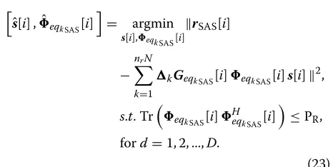
According to the ML criterion, the optimization prob-lem can be written as
After we obtains[ˆi] by using an ML detector described in the previous section, we can rewrite the Lagrangian expression of (23) as
L =rSAS[i]−
Table 2Summary of the DT-ACMO SG algorithm in MAS
1: Generate[0] randomly with the power constraint.
where λ stands for the Lagrange multiplier. In order to obtain the optimal adjustable code matrices, we have to expand the right-hand side of L, compute the gradient terms with respect to thekth matrixeqkSAS[i], and equate them to zero, which results in
ˆ
led derivation is shown in the Appendix. Note that the last term in (24) which contains the Lagrange multiplierλis not considered in the optimization algorithm. The value ofλcan be obtained by substituting (25) into (24), or this procedure can be avoided by employing the normalization to achieve the power constraint as derived in (12) in order to reduce the computational complexity.
3.2.1 RLS code matrix estimation algorithm
The RLS optimization problem of the adjustable code matrices is written as
ˆ
By expanding the right-hand side of (26), taking the gra-dient with respect to∗eqk
The power constraint is enforced by the normalization strategy after the optimization. In order to implement the RLS estimation algorithm, we can define
SAS[i]=
By employing the matrix inversion lemma in [33], we can obtain
expression of the code matrix is given by
eqkSAS[i]=λZSAS[i−1]PSAS[i]+reSAS[i]rHkSAS[i]PSAS[i]
By using the algorithm in Table 1, we can obtain the optimal code matrices, and the only differences are the initialized matrices P[ 0]= δ−1IN×N, andZ[ 0]= IN×N
for SAS.
3.2.2 SG code matrix estimation algorithm
The SG estimation algorithm for the code matrix eqkSAS[i] is derived in this section. As shown in (25), the inversion of the matrices is required and the computa-tional complexity will be increased by employing a large number of relay nodes or number of antennas.
We can rewrite the expression of the received vector for SAS in (22) at the destination node as
rSAS[i]= lent channel matrix combining with the delay profile, the DSTC scheme, and the channel between thejth antenna of thekth relay node and the destination node. The ML-based Lagrangian expression is derived as
L =
and a simple adaptive algorithm for determining the adjustable code matrices can be derived by taking the instantaneous gradient terms of the Lagrangian expres-sion with respect to the scalar φk∗
∇Lφ∗
kjSAS[i]= ∇ ⎛
⎝rSAS[i]−
nr
k=1
N
j=1
Gk
eqkj
SAS
[i]φkjSAS[i]ˆs[i] ⎞ ⎠
H
φ∗
kjSAS[i]
re[i]= −sH[i]
Gk
eqkj
SAS [i]
H
re[i] , (35)
wherere[i]= rSAS[i]−knr=1Nj=1Geqkkj
SAS[i]φkjSAS[i]s[ˆi] stands for the error vector. After we obtain (35), the pro-posed SG algorithm can be obtained by introducing a step sizeβinto a gradient optimization algorithm to update the result until the convergence is reached. The DT-ACMO SG algorithm for SAS is given by
φkjSAS[i+1]=φkjSAS[i]+β
sH[i]
Gk
eqkj
SAS [i]
H
re[i]
,
(36)
By following the steps in Table 2, we have the DT-ACMO SG algorithm in SAS.
4 DT-ACMO algorithm with opportunistic DSTCs
In this section, we extend the DT-ACMO algorithms to cooperative systems with the AF strategy using the opportunistic relaying schemes in [18] and design delay-tolerant adjustable code matrices opportunistic relaying optimization (DT-ACMORO) algorithms. The oppor-tunistic relaying techniques in [18] for the AF strategy provide optimal relay and antenna selection algorithms which can achieve a lower BER performance compared to the traditional equal power allocation schemes for the AF protocol systems. Three opportunistic relaying algorithms are designed in [18] for two-hop cooperative systems and explained as follows:
1. Opportunistic AF scheme: using DSTC schemes at the source node in the first phase and selecting the best relay nodes in the second phase for forwarding what the relay received
2. Opportunistic source scheme: selecting the best antenna at the source node and using DSTCs at the relay nodes in the second phase
3. Fully opportunistic scheme: optimizing the transmitting power both at the source node and at the relay nodes.
A feedback channel is employed which allows the des-tination node to inform the optimal relay and to send back the optimized code matrices to the relays. The delay profiles for different relay nodes are considered in the design described in this section. For simplicity, we show the design of the system model with AF protocol and DT-ACMORO algorithms for MAS.
The system model is described as follows. The power used at the source node is defined as P1, and the total
power used among all the relay nodes isP2 =Nk=1P2,k,
wherek denotes the number of relay nodes. In the first phase, the source node will encode the modulated sym-bols that are organized in a vector s[i] to an T × N
space-time coding (STC) matrix, which gives
S[i]=[A1s[i] A2s[i] ...ANs[i] ] , (37)
whereAn,n = 1, ...,N, areT ×T unitary matrices. The
source node broadcasts the STC matrix to thenr relay
nodes after the encoding, and the received symbol at the
kth relay node is described by
Xk[i]=
P1T
N S[i]Fk+Nk, (38)
whereFkdenotes theN×Nchannel matrix between the
source node and thekth relay node andNkis the matrix
whose entries are complex zero-mean complex random variables with varianceσn21.
In the second phase, according to the AF protocol, the received symbols will be re-encoded and amplified before being forwarded to the destination node. It is worth to mention that instead of transmitting the fixed linear func-tions of the received matrix from the source node in [18], we generate the adjustable code matrices k[i] for the
kth relay node and multiply them by the received sym-bol matrices before forwarding them to the destination node. The delay profilekfor each relay node is
consid-ered as well. The communication between the relays and the destination node can be described by
R[i]=
nr
k=1
N
j=1
ρk,jgk,j[i]yk,j[i]k,j[i]+Nd, (39)
where
ρk,j=
Pk,j
σ2
FkP1+σ 2
n1 ,
yk,j[i]=φk,j[i]Xk[i] ,
(40)
substituting (38) and (40) into (39), we can obtain the received matrix derived as
R[i]= matrix with the delay profile andeqk,j[i] stands for the (N(δmax+T)×N(δmax+T))block diagonal adjustable
code matrix. The noise vectorsnkandndare the columns
ofNk andNd, respectively. Therefore, the opportunistic
relaying algorithm is given by
ˆ
According to the opportunistic relaying algorithms [18], the relays which can achieve the highestSNRins are
cho-sen to forward the symbols with transmission powerP2.
The DT-ACMORO can be implemented by firstly calcu-lating the optimized adjustable code matrices using the DT-ACMO algorithms proposed in Tables 1 or 2, fol-lowed by choosing the optimal relay node using the SNR expressed in (43).
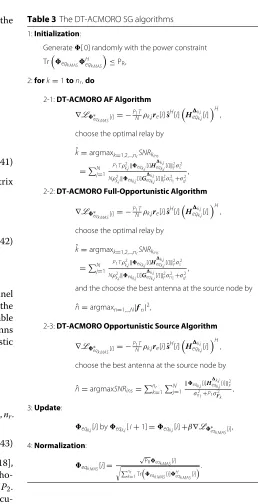
A summary of the DT-ACMORO algorithms is shown in Table 3, and different opportunistic relaying algorithms in [18] are considered. Note that the DT-ACMORO fully opportunistic and opportunistic source algorithms need the CSI between the source node and the relaysfnin order to maximize the received SNR and choose the optimal antenna at the source node [18], wherefnis the 1×nrN
channel vector between the nth antenna at the source node and all the relay nodes.
Table 3The DT-ACMORO SG algorithms
1:Initialization:
Generate[ 0] randomly with the power constraint Treqk MASHeqk MAS
≤PR,
2:fork=1tonr,do
2-1:DT-ACMORO AF Algorithm
∇L∗
choose the optimal relay by ˆ
2-2:DT-ACMORO Full-Opportunistic Algorithm
∇L∗
choose the optimal relay by
ˆ
and the choose the best antenna at the source node by
ˆ
n=argmaxn=1,...,N|fn|2,
2-3:DT-ACMORO Opportunistic Source Algorithm
∇L∗
choose the best antenna at the source node by
ˆ
5 Analysis of the proposed DSTBC schemes and the algorithms in MAS and SAS
be achieved and the delay tolerance of the SAS and MAS configurations is different.
5.1 Rank criterion
The DSTBC schemes in SAS perform encoding across relay nodes, while the DSTBC schemes in MAS employ full STBCs at each relay node. For simplicity, we consider 2 single-antenna relay nodes for SAS and 1 relay node with 2 antennas for MAS with the same DSTC scheme for a fair comparison. In the standard STBCs in SAS such as the Alamouti scheme, the code word consists of matrices in the form
wheres1ands2are symbols from a desired PSK or QAM
constellation. The first antenna sends the first row inC,s1
and−s∗2, to the destination node, and the second antenna sends the symbolss2ands∗1during the transmission
inter-val. It is important that the determinant of the code matrix is different from zero unless boths1=0 ands2=0.
The difference matrix of the standard Alamouti STBC scheme between two codewords can be expressed as
C=C1−C2=
full. According to the rank criterion in [34] for the STCs, the Alamouti scheme achieves full diversity.
However, the standard Alamouti scheme is not delay-tolerant with SAS. Consider a delay profile =[ 0 1] in which the second transmission from the second relay node is one-symbol slot later than the first one. Then, the difference matrix is given by
C=C1 −C2 =
which suffers a rank reduction. Hence, the Alamouti scheme in SAS cannot achieve the full diversity when a time delay is introduced.
In contrast to the SAS case, in MAS withnr = 2 relay
nodes, the standard Alamouti scheme can be obtained in each individual relay node; with the delay profile = [ 0 1], the delayed matrix is described by
C=Cδ1+Cδ2 =
then the difference matrix between the 2 codewords is given by
which achieves the same rank as (48) even when s1 =
0 or s2 = 0. Therefore, the delay tolerance of a DSTC
scheme with MAS depends on the size of the code matrix.
5.2 Error probability
In the SAS configuration, the received matrix at the desti-nation node in (3) and (5) can be rewritten as
RRDSAS[i]=GRDSAS[i]MRDSAS[i]+NRD[i] , (50)
where MRDSAS[i]= [i]SAS[i]MRDSAS[i] denotes the delayed randomized DSTCs encoding across the relays. Let s1 and s2 denotes two possible modulated symbol
vectors, and given the code matrix MRDSAS[i], the PEP of decoding s1 to s2 has the following Chernoff upper
bound [34]
denotes the auto-correlation matrix of the difference code matrices. The conditional average PEP of the delayed codeword matrix over all possible symbols and delay profiles can be written as
where S is the set of all possible combinations of the symbol vectors.
The Chernoff upper bound in (51) with a high SNR scenario can be approximately written as
Ps1,s2
correlation matrix andλn denotes the nth eigenvalue of
RSAS. The diversity order of the code matrix is given byrN
and is determined by the minimum rank of the correlated code matrix. According to (47), the rank reduction affects the diversity order of the code matrix so that the Alamouti matrix code in SAS cannot achieve the full diversity and is not a delay-tolerant code.
In MAS withnr = 2 relay nodes, the received symbol
matrix at the destination node can be rewritten as
RRDMAS[i]= node with the delay profile, the equivalent channel matrix is denoted as GRDMASeq[i], and the delayed code matrix is MRDMASeq[i]. The PEP of the decoding at the desti-nation node is upper bounded by the Chernoff bound given by matrix of the difference code matrices. The Chernoff upper bound of the conditional average PEP with a high SNR over all possible symbols and delay profiles can be expressed as
correlation matrix andλn is thenth eigenvalue ofRMAS.
The diversity order depends on the minimum rankrand according to (49) that is r = N which guarantees that the full diversity order can be achieved. According to [34], the rank and diversity analysis can be considered as the design criterion of the delay-tolerant DSTC schemes in cooperative communication systems in a high SNR sce-nario. The optimization algorithm derived in the previous section ensures that the design of the STC scheme is delay-tolerant for any SNR and achieves a high coding gain. The ML detection algorithm is employed in order to achieve the full receive diversity. The upper bound derived in this section is relatively loose and becomes tighter at high SNR values but allows a designer to infer that the diversity order obtained with DT-ACMORO algorithms will remain the same as those of existing techniques but there will be coding gains.
The design of the DT-ACMORO algorithms achieves a lower BER performance by employing the proposed DT-ACMORO algorithms in cooperative systems with opportunistic relaying methods in [18]. As a result, the PEP analysis of the DT-ACMORO algorithms in MAS and SAS is the same as that of the DT-ACMO algorithms. The only difference is the channel matrixGRD[i] in (50) and
(54) denotes theN×Nchannel matrix between the opti-mal relay node and the destination node in SAS and MAS, respectively.
5.3 Convergence analysis
As shown in the previous sections, the proposed ML-based DT-ACMO algorithms allow the optimization of the code matrix [i] adaptively. In this section, we briefly study the differentiability of the cost func-tions that are optimized by the proposed algorithms and the convergence of the DT-ACMO RLS and SG algorithms.
5.3.1 Differentiability of the cost functions
In Section 3, we compute an instantaneous gradient of the Lagrangian (9) to derive the proposed DT-ACMO algo-rithms, while in this subsection, we show the proof of differentiability of (9).
According to the definition of differentiability [32], the limit of (9) has to exist and should be equal to zero when the change inapproaches0, where0is the zero matrix. The differentiability problem is given by
lim Q→0
L(+Q)−L()
Q =0, (57)
lim Q→0
rMAS[i]−nkr=1
eqkMAS[i]+Q
GeqkMAS[i]ˆs[i] 2− r
MAS[i]−nk=r1eqkMAS[i]GeqkMAS[i]ˆs[i] 2
Q =0. (58)
After substituting (5) into (58) and expansion of the above equation, we can obtain
lim Q→0
nD[i]−QGeqkMAS[i]ˆs[i] 2− n
D[i]2
Q =0,
(59)
where nD[i] is the noise vector generated at the
des-tination node and it is not related to the code matrix
eqkMAS[i] orQ. As a result, we can ignore the influence from the noise and rewrite the expression of the limit as
lim Q→0
QGeqkMAS[i]ˆs[i] 2
Q =Qlim→0GeqkMAS[i]ˆs[i] 2QH
= GeqkMAS[i]s[ˆi] 20=0.
(60)
As shown in (60), the limit of (9) is equal to0when the change of the code matrixQapproaches0. The differen-tiability of the optimization problem is proved. The same procedure could be used for the SAS scheme.
5.3.2 Convergence analysis of DT-ACMO algorithms in MAS The ML- and RLS-based DT-ACMO algorithms in MAS optimize the adjustable code matrix, and we can ana-lyze the Hessian matrix of (9) and check its positive (semi-)definiteness. By taking the second-order partial derivatives of the Lagrangian cost function in (9), we can obtain the second-order conditions derived as
H(L)= ∂
∂
eqkMAS[i] ⎛ ⎜
⎝ ∂L
∂
eqkMAS[i] ∗
⎞ ⎟ ⎠
= ∂
∂
eqkMAS[i]
−rMAS[i]sH[i]GHeqkMAS[i]
+ eqkMAS[i]GeqkMAS[i]s[i]s
H[i]GH eqkMAS[i]
=GeqkMAS[i]s[i]s
H[i]GH eqkMAS[i] ,
(61)
where the first term s[i]sH[i] is a positive matrix and the rest of the terms denotes the multiplication of the equivalent channel vectors which is a positive-definite matrix and the problem is convex. Therefore, the Hes-sian matrix of the Lagrangian cost function is a positive-definite matrix, which ensures the RLS-based DT-ACMO algorithms converge to the global optimum under the usual assumptions used to prove the convergence of these algorithms for convex problems [25].
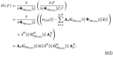
5.3.3 Convergence analysis of DT-ACMO algorithms in SAS The ML-based SG ACMO algorithm for SAS optimizes the adjustable code matrix, and by taking the second-order partial derivatives of the Lagrangian cost function in (24), we can obtain
H(L)= ∂ ∂eqkSAS[i]
∂L
∂(eqkSAS[i])∗
= ∂
∂eqkSAS[i]
rSAS[i]−
nrN
k=1
kGeqkSAS[i]eqkSAS[i]sˆ[i]
× ˆsH[i]GHeqk
SAS[i]
H k
=kGeqkSAS[i]ˆs[i]ˆs
H [i]GHeqk
SAS[i]
H k,
(62)
As shown in the previous section, the Hessian matrix of the Lagrangian cost function is a positive-definite matrix so that the ML-based SG DT-ACMO algorithm in SAS converges to the global optimum under the usual assump-tions used to prove the convergence of these algorithms for convex problems.
5.4 Computational complexity
In this subsection, we describe the computational com-plexity of the proposed and existing algorithms in terms of complex multiplications, as shown in Table 4. The computational complexity here refers to the cost of encod-ing the data usencod-ing the existencod-ing Alamouti and the pro-posed DT-ACMO and DT-ACMORO algorithms. Table 4 shows that the proposed DT-ACMO-RLS technique and the DT-ACMORO algorithm are the most computation-ally demanding, the randomized Alamouti (R-Alamouti) approach has a comparable complexity to the DT-ACMO-SG technique, and the simplest approach is the distributed Alamouti (D-Alamouti) scheme.
Table 4Computational complexity
Algorithms Multiplications
D-Alamouti O(N(λmax+T))
R-Alamouti ON(λmax+T)2
DT-ACMO-SG O(N(λmax+T)2
DT-ACMO-RLS O(4N(λmax+T)2
6 Simulations
The simulation results are provided in this section to assess the proposed schemes and algorithms. The coop-erative MIMO system considered employs AF and DF protocols with the distributed Alamouti (D-Alamouti) STBC scheme in [9], randomized Alamouti (R-Alamouti) in [15], and linear dispersion code (LDC) in [35] using BPSK and QPSK modulation in a quasi-static block fad-ing channel with AWGN. The effect of the direct link is also considered. It is possible to employ different DSTC schemes with a simple modification and to incorporate the proposed algorithms. The cooperative MAS configu-ration equipped with nr = 1, 2 relay nodes andN = 2
antennas at each node, while the cooperative SAS scheme employedN = 1, 2 antennas at the source node and the destination node andnr = 1, 2 relay nodes with a single
antenna. In the simulations, we set the symbol powerσs2 as equal to 1, the delay profiles are perfectly known at the destination, and the power of the adjustable code matrix in the DT-ACMO algorithm is normalized. The SNR in the simulations is the received SNR which is calculated by
SNR= DD[i]2F nD[i]nHD[i]2F
.
The BER performance of the D-Alamouti and the R-Alamouti in the cooperative MAS and SAS configura-tions without delay are shown in Fig. 2. The solid curves are the BER curves without the direct link (DL) and the dashed ones are that with the DL. SAS employing a single antenna at each node and the AF strategy with and with-out the DL have the worst BER performance compared
to SAS and MAS employing multiple antennas and relay nodes. The cooperation of the DL helps SAS to achieve a higher diversity gain and lower the BER. In SAS employing
N = 2 antennas at the source node and the destina-tion node with nr = 2 single-antenna relay nodes, and
MAS employing the same number of the antennas at the source node and the destination node withnr = 1 relay
node usingN=2 antennas, the superposition of the BER curves can be observed. With the cooperation of the DL, a higher order of diversity can be achieved. The simulation results lead to the conclusion that with the same number of antennas at the source node and the destination node in SAS and MAS, if the number of the relay nodes with single antenna is the same as the number of multi-antenna relay nodes, the same diversity order and BER performance can be achieved when the synchronization is perfect at the relay node.
In Fig. 3, BER curves of different DSTC schemes with-out the DL using an ML detector are compared using the SAS scheme with N = 2 relay nodes. Different delay profiles are considered to evaluate the performance of D-Alamouti, R-Alamouti using BPSK, and R-LDC using QPSK in SAS. As shown in Fig. 3, the R-Alamouti scheme improves the performance by about 2 dB without the DL compared to the D-Alamouti scheme when perfect syn-chronization is considered. When the delay profile = [ 0, 1] is considered among the relay nodes, it is shown that the D-Alamouti and R-Alamouti are not delay-tolerant schemes in SAS. The R-LDC schemes using QPSK modu-lation constelmodu-lation with different delay profiles are shown
0 5 10 15 20 25 30
10−6 10−4 10−2 100
SNR (dB)
BER
N=1 at S, R and D, SAS, AF (DL / no DL) N=2 at S, R and D, MAS, DF (DL / no DL) N=2 at S R and D, MAS, n
r=1, AF (DL / no DL) N=2 at S R and D, MAS, n
r=1, DF (DL / no DL) N=2 at S and D, N=1 at R, SAS, n
r=2, AF (DL / no DL)
0 2 4 6 8 10 12 14 16 10−6
10−4 10−2 100
SNR (dB)
BER
D−Alamouti(0,0) [8] D−Alamouti(0,1) R−Alamouti(0,0) [4] R−Alamouti(0,1) R−LDC(0,0) [24] R−LDC(0,1)
DT−ACMO−Alamouti(0,1) DT−ACMO−LDC(0,1)
Fig. 3BER performance vs. SNR for SAS
in Fig. 3. It is shown in Fig. 3 that the R-LDC in SAS is not a delay-tolerant scheme because of the degradation of the BER performance. When employing the proposed DT-ACMO algorithm in SAS, a performance improvement is obtained in R-Alamouti and R-LDC schemes. However, the BER curves of the Alamouti and LDC schemes using
DT-ACMO algorithms are still worse than that of the Alamouti and LDC schemes with perfect synchronization among the relays.
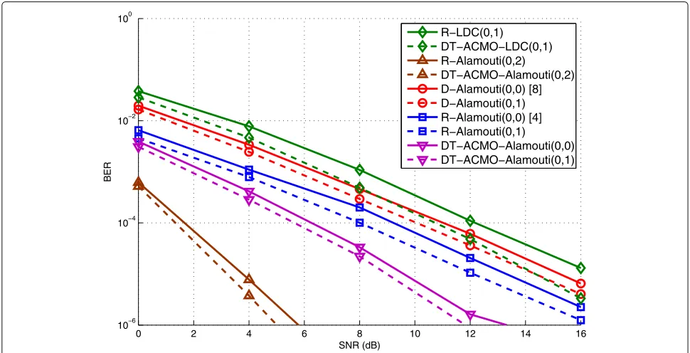
The proposed DT-ACMO algorithm is compared with different DSTC schemes and different delay profiles in MAS in Fig. 4. In the proposed algorithms, the DF strategy
0 2 4 6 8 10 12 14 16
10−6 10−4 10−2 100
SNR (dB)
BER
R−LDC(0,1)
DT−ACMO−LDC(0,1) R−Alamouti(0,2)
DT−ACMO−Alamouti(0,2) D−Alamouti(0,0) [8] D−Alamouti(0,1) R−Alamouti(0,0) [4] R−Alamouti(0,1)
DT−ACMO−Alamouti(0,0) DT−ACMO−Alamouti(0,1)
is employed which requires re-encoding at the relay nodes, and a full STC scheme is obtained at each of the
nr =2 relay nodes. The results illustrate that without the
DL, by making use of the randomized encoding technique in [15], a 2-dB BER performance improvement can be achieved compared to the D-Alamouti scheme with and without the delay. The simulation results illustrate that MAS with different DSTC schemes when the same delay profiles are considered, a 1-dB performance improvement is obtained. It is because when the full DSTC schemes can be obtained at the relay nodes as employed in MAS, at the destination node, a delayed symbol matrix with increased dimension is received which means the observation win-dow is bigger than that with the non-delayed MAS. When the DT-ACMO algorithms are employed in Alamouti and LDC schemes, better BER performances can be achieved. With the consideration of the delay profiles, the results indicate that the diversity order will not be reduced, and using the DT-ACMO RLS algorithm, an improved per-formance is achieved with 3 dB of gain as compared to employing the RSTC algorithm in [15] and 5 dB of gain as compared to traditional DSTBC algorithms.
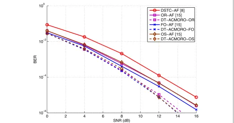
The proposed DT-ACMORO algorithms with Alamouti scheme and an ML receiver are compared with MAS in Fig. 5. N = 2 antennas at each node and nr = 2 relay
nodes are employed. Different delay profiles are consid-ered in different relay nodes. It is shown in the figure that the BER result of the cooperative system with DSTC schemes and AF protocol achieves a diversity order of 2, and by employing opportunistic relaying (OR), fully
opportunistic (FO), and opportunistic source (OS) algo-rithms, a 2- to 3-dB BER improvement can be further achieved, respectively. In [18], the benefits of employing three opportunistic relaying algorithms are explained. In the proposed DT-ACMORO algorithms, the DT-ACMO algorithms are combined with different opportunistic relaying algorithms in order to achieve a BER improve-ment as shown in the previous section. According to the simulation results in Fig. 5, a 2- to 3-dB gains can be achieved by using DT-ACMORO compared to the systems only use opportunistic relaying algorithms. It is worth to mention that different DT-ACMORO algorithms require different computational complexities as shown in Table 3, and the DT-ACMORO-FO algorithm which requires the choice of the best antenna at the source node and the use of the best relay node can achieve the best BER performance as compared with the DT-ACMORO-OR and DT-ACMORO-OS algorithms.
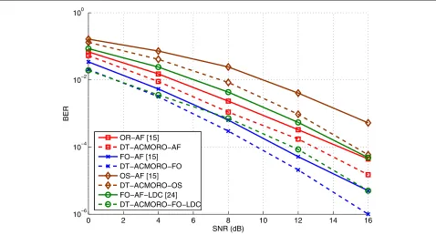
In Fig. 6, the proposed DT-ACMORO SG algorithms are employed among the relay nodes in SAS. Compared to the opportunistic algorithms in [18], the DT-ACMORO algorithms achieve a 2- to 4-dB improvement compared to the original opportunistic relaying algorithms as shown in Fig. 6. When comparing the curves in Fig. 6 to those in Fig. 5, it is noticed that the diversity order of the curves in Fig. 6 and that in Fig. 5 are the same because the same DSTBC schemes are employed in MAS and SAS; however, the BER performances in Fig. 3 are worse than that in Fig. 5. The reason for worse BER performances in SAS is due to the lower number of antennas used in
0 2 4 6 8 10 12 14 16
10−6 10−4 10−2 100
SNR (dB)
BER
DSTC−AF [8] OR−AF [15] DT−ACMORO−OR FO−AF [15] DT−ACMORO−FO OS−AF [15] DT−ACMORO−OS
0 2 4 6 8 10 12 14 16 10−6
10−4 10−2 100
SNR (dB)
BER
OR−AF [15] DT−ACMORO−AF FO−AF [15] DT−ACMORO−FO OS−AF [15] DT−ACMORO−OS FO−AF−LDC [24] DT−ACMORO−FO−LDC
Fig. 6BER performance vs. SNR for DT-ACMORO SG algorithm for SAS
SAS according to the opportunistic relaying algorithms. In SAS, nr = 2 relay nodes with a single antenna are
employed, and after the optimization, only one relay node withN=1 antenna is chosen to transmit the re-encoded information symbols. On the contrary, the best relay node in MAS contains N = 2 antennas to forward the re-encoded DSTC scheme to the destination which ensures the complete DSTC scheme is received at the destination node.
7 Conclusions
We have proposed a delay-tolerant adjustable code matrix optimization (DT-ACMO) scheme and algorithms for cooperative MIMO systems with a feedback channel using an ML receiver at the destination node to mitigate the effect of the delay associated with DSTCs from relay nodes. The MAS and SAS configurations have been ana-lyzed by comparing the pairwise error probability of the delayed DSTCs and the rank criterion. In order to achieve a better BER performance and eliminate the computation complexity at the destination node, we have introduced the SG and RLS algorithms in the proposed design. We have extended the proposed algorithms to cooperative MIMO systems with the AF strategy and opportunis-tic relaying algorithms in order to devise delay-tolerant adjustable code matrix opportunistic relaying optimiza-tion (DT-ACMORO) algorithms. The simulaoptimiza-tion results have illustrated the performance of the two different cooperative systems with the same number of transmit and receive antennas and the advantage of the proposed
DT-ACMO and DT-ACMORO algorithms by comparing them with the cooperative network employing the tradi-tional DSTC scheme and the RSTC scheme. The proposed algorithms can be used with different DSTC schemes and can also be extended to cooperative systems with any number of antennas.
Appendix
We show how to obtain the optimal adjustable code matri-ces in the SAS. The ML-based optimal problem is derived in (24). We can expand the right-hand side ofL in order to obtain the expression ofeqkSAS[i], as described by
L =
rSAS[i]−
nrN
l=1
lGeqlSAS[i]eqlSAS[i]ˆs[i]
×
rSAS[i]− nrN
k=1
kGeqkSAS[i]eqkSAS[i]ˆs[i]
H
=rSAS[i]rHSAS[i]−rSAS[i] nrN
k=1
kGeqkSAS[i]eqkSAS[i]ˆs[i]
H
− nrN
l=1
lGeqlSAS[i]eqlSAS[i]ˆs[i]
rHSAS[i]
+ nrN
l=1
lGeqlSAS[i]eqlSAS[i]ˆs[i]
× nrN
k=1
kGeqkSAS[i]eqkSAS[i]sˆ[i]
H ,
and if we focus on the kth adjustable matrix eqkSAS[i], take the gradient terms with respect to it, and equate the result to 0, we can obtain
dL to the other side of the equation and take the pseudo-inverse of the equation and we can obtain the optimal adjustable code matrix as
eqkSAS[i]=
The authors would like to thank CNPq and FAPERJ from partially funding this work.
Authors’ contributions
TP has contributed towards the development of the system model, the algorithms, the analysis, and the simulations. In particular, he has written the code that resulted in the curves shown in the simulations section. RL has contributed towards the development of the system mode, the algorithms, and the analysis. As the supervisor of TP, he has proofread the paper several times and provided guidance throughout the whole preparation of the manuscript. Both authors read and approved the final manuscript.
Competing interests
The authors declare that they have no competing interests.
Publisher’s Note
Springer Nature remains neutral with regard to jurisdictional claims in published maps and institutional affiliations.
Received: 26 April 2017 Accepted: 28 December 2017
References
1. JN Laneman, GW Wornell, Cooperative diversity in wireless networks: efficient protocols and outage behaviour. IEEE Trans. Inf. Theory.50(12), 3062-3080 (2004)
2. JN Laneman, GW Wornell, Distributed space-time-coded protocols for exploiting cooperative diversity in wireless networks. IEEE Trans. Inf. Theory.49(10), 2415-2425 (2003)
3. S Yiu, R Schober, L Lampe, Distributed space-time block coding. IEEE Trans. Wir. Commun.54(7), 1195–1206 (2006)
4. P Clarke, RC de Lamare, Transmit diversity and relay selection algorithms for multi-relay cooperative MIMO systems. IEEE Trans. Veh. Technol.
61(3), 1084–1098 (2012)
5. J Gu, RC de Lamare, M Huemer, Buffer-aided physical-layer network coding with optimal linear code designs for cooperative networks. IEEE Trans. Commun. (2017)
6. Y Hei, W Li, M Li, Z Qiu, W Fu, Optimization of multiuser MIMO cooperative spectrum sensing in cognitive radio networks. Cogn. Comput.7(3), 359–368 (2015)
7. P Salvo Rossi, D Ciuonzo, G Romano, Orthogonality and cooperation in collaborative spectrum sensing through MIMO decision fusion. IEEE Trans. Wirel. Commun.12(11), 5826–5836 (2013)
8. P Clarke, RC de Lamare, Joint transmit diversity optimization and relay selection for multi-relay cooperative MIMO systems using discrete stochastic algorithms. IEEE Commun. Lett.15, 1035–1037 (2012) 9. RC de Lamare, R Sampaio-Neto,Blind adaptive MIMO receivers for
space-time block-coded DS-CDMA systems in multipath channels using the constant modulus criterion, vol. 58, (2010), pp. 21–27
10. H El Gamal, MO Damen, Universal space-time coding. IEEE Trans. Inf. Theory.49(5), 1097–1119 (2003)
11. MO Damen, AR Hammons, Delay-tolerant distributed-TAST codes for cooperative diversity. IEEE Trans. Inf. Theory.53(10), 3755–3773 (2007) 12. M Torbatian, MO Damen, On the design of delay-tolerant distributed
space-time codes with minimum length. IEEE Trans. Wirel. Commun.
8(2), 931–939 (2009)
13. Z Zhimeng, Z Shihua, A Nallanathan, Delay-tolerant distributed linear convolutional space-time code with minimum memory length under frequency-selectivechannels.IEEETrans. Wirel. Commun.8(8), 3944–3949 (2009) 14. MR Bhatnagar, A Hjorungnes, M Debbah, Delay-tolerant
decode-and-forward based cooperative communication over Ricean channels. IEEE Trans. Wirel. Commun.9(4), 1277–1282 (2010) 15. B Sirkeci-Mergen, A Scaglione, inIEEE Trans. Signal Process. Randomized
space-time coding for distributed cooperative communication, vol. 55, (2007), pp. 5003–17
16. T Peng, RC de Lamare, A Schmeink, inIEEE Trans. Commun. Adaptive distributed space-time coding based on adjustable code matrices for cooperative MIMO relaying systems, vol. 61, (2013), pp. 2692–2703 17. Y Zou, Y Yao, B Zheng, Opportunistic distributed space-time coding for
decode-and-forward cooperation systems. IEEE Trans. Signal Process.60, 1766–1781 (2012)
18. B Maham, A Hjørungnes, Opportunistic relaying for MIMO
amplify-and-forward cooperative networks. Wirel. Pers. Commun (2012). https://doi.org/10.1007/s11277-011-0499-9
19. D Gunduz, E Erkip, Opportunistic cooperation by dynamic resource allocation. IEEE Trans. Wirel. Commun.6, 1446–1454 (2007) 20. J Abouei, H Bagheri, A Khandani, An efficient adaptive distributed
space-time coding scheme for cooperative relaying. IEEE Trans. Wirel. Commun.8(10), 4957–4962 (2009)
21. B Maham, A Hjφrungnes, G Abreu, Distributed GABBA space-time codes in amplify-and-forward relay networks. IEEE Trans. Wirel. Commun.8(4), 2036–2045 (2009)
22. S Yang, J-C Belfiore, Optimal space-time codes for the MIMO amplify-and-forward cooperative channel. IEEE Trans. Inf. Theory.53(2), 647–663 (2007)
23. B Maham, A Hjφrungnes, BS Rajan, in2010 IEEE Wireless Communications and Networking Conference (WCNC), 18-21 April 2010. Quasi-orthogonal design and performance analysis of amplify-and-forward relay networks with multiple-antennas., (Sydney, Australia, 2010), pp. 1–6
25. S Haykin,Adaptive filter theory, 4th ed. (Prentice- Hall, Englewood Cliffs, NJ, 2002)
26. A Kocian, BH Fleury, inIEEE Trans. Commun.EM-based joint data detection and channel estimation of DS-CDMA signals., vol. 51, (2003), pp. 1709–1720
27. RC de Lamare, R Sampaio-Neto, A Hjorungnes, Joint iterative interference cancellation and parameter estimation for cdma systems. IEEE Commun. Lett.11(12), 916–918 (2007)
28. RC de Lamare, R Sampaio-Neto, Minimum mean-squared error iterative successive parallel arbitrated decision feedback detectors for DS-CDMA systems. IEEE Trans. Commun.56(5), 778–789 (2008)
29. RC de Lamare, Adaptive and iterative multi-branch MMSE decision feedback detection algorithms for multi-antenna systems. IEEE Trans. Wirel. Commun.12(10), 5294–5308 (2013)
30. B Hassibi, H Vikalo, On the sphere-decoding algorithm I.Expected complexity. IEEE Trans. Signal Process.53(8), 2806–2818 (2005) 31. G Romano, D Ciunzo, P Salvo Rossi, F Palmieri, Low-complexity
dominance-based sphere decoder for MIMO systems. Signal Process.
93(9), 2500–2509 (2013)
32. DP Bertsekas,Nonlinear programming, 2nd Ed, (Athena Scientific, 1999) 33. DJ Tylavsky, GRL Sohie, Generalization of the matrix inversion lemma.
Proc. IEEE.74(7), 1050–1052 (1986)
34. H Jafarkhani,Space-time coding theory and practice. (Cambridge University Press, 2005)