R E S E A R C H
Open Access
Joint routing and scheduling in multi-channel
capillary machine-to-machine networks
Taeshik Shon
1, Hyo Hyun Choi
2and Eui-Jik Kim
3*Abstract
In recent times, machine-to-machine (M2M) communication is considered the most promising solution for
revolutionizing future intelligent pervasive applications. The capillary M2M network is a key component of the M2M system, and it should support a data rate that is sufficient to accommodate various vertical applications with limited resources of end devices. This paper presents a joint routing and scheduling (JRS) framework for a capillary M2M network. To achieve the conflicting goals of maximizing network performance and conserving energy, the JRS framework is designed with an integrated concept of routing and transmission scheduling, which provides time division multiple access (TDMA)-based transmission scheduling based on the established routing path of data. Moreover, to extend the number of available transmission frames and enhance network performance, JRS uses the multi-channel communication approach. Experimental results of the prototype implementation demonstrate that JRS outperforms conventional schemes, even under heavy traffic conditions.
Keywords:Capillary machine-to-machine, Prototype implementation, Routing, Transmission scheduling
1. Introduction
In recent times, machine-to-machine (M2M) communi-cation has emerged as a cutting-edge technology for next-generation communication, and it is considered the most promising solution for revolutionizing future intel-ligent pervasive applications [1-6]. Wireless M2M com-munication is a form of data transfer that facilitates direct communication among machines with little or no human intervention. Recently, considerable effort has been put into M2M standardization [7,8]. For example, the European Telecommunications Standards Institute has launched the M2M Technical Committee with the purpose of developing an end-to-end architecture for M2M communications [9] in which the capillary M2M network is considered a key component of the M2M system. A capillary M2M network is a generic term that refers to any network technology that provides physical and medium access control (MAC) layer connectivity between various M2M devices connected to the same capillary M2M network or that allows an M2M device to gain access to a public network via a router or a
gateway. In [10], it is also referred to as an M2M area network.
Capillary M2M networks should support a data rate that is sufficient to accommodate various kinds of verti-cal applications with the limited resources of end de-vices. In other words, to deliver various kinds and sizes of M2M data effectively, capillary M2M networks must be able to both maximize the network throughput and conserve energy. Here, we discuss several issues that need to be considered in the design of a capillary M2M software framework to meet the above requirements.
The first issue pertains to the MAC protocol, which plays a key role in determining the network throughput, delay, power consumption, etc. A large number of MAC protocols have been proposed for sensor networks and personal area networks, with energy efficiency as the primary design criterion. The most common of these protocols are the contention-based carrier sense mul-tiple access (CSMA) scheme [11-17] and the schedule-based time division multiple access (TDMA) scheme [18-20]. CSMA is the natural solution because of its simplicity and flexibility. With the CSMA-based MAC protocol, individual devices in a network can decide how and when to access the radio medium without any time synchronization or topology information. However, their * Correspondence:euijik.kim@kt.com
3
Advanced Institute of Technology, KT Corporation, Umyeon-dong, Seocho-gu, Seoul 137-792, South Korea
Full list of author information is available at the end of the article
performance can be significantly degraded in situations of high contention because of the high overhead accrued for resolving collisions. In addition, overhearing and idle listening also affect energy consumption. In con-trast, TDMA utilizes time synchronization among neigh-boring devices to achieve collision-free transmission by assigning unique transmission time slots to individual devices. TDMA can generally achieve higher network throughput in situations of high contention, as well as energy efficiency. However, scheduling the time slots is notoriously difficult to achieve in a distributed fashion, and strict synchronization is also required. In addition, TDMA often suffers from inefficiency in low contention situations, because a device can transmit only during its scheduled time slots. Hu et al. [21] reported that while CSMA suffers from inefficiency in high contention situa-tions, TDMA operates in a converse manner. Therefore, the strengths of both types of MAC protocols must be combined while offsetting their shortcomings.
The second issue concerns the routing path of data from end devices to an M2M gateway. Network design has traditionally followed the principle of layering. Previ-ous work in this area has focused largely on the design of link-level protocols [22-28], and some previous papers address routing for such a network [29,30]. However, the formation of the network topology affects the operation of the MAC protocol, which in turn, significantly affects the performance factors, such as network throughput and energy consumption. Thus, the network layer must be designed to include a routing protocol in conjunction with diverse MAC-related scheduling.
In this paper, we propose a joint routing and schedul-ing (JRS) architecture in a capillary M2M network that seeks to address all the aforementioned issues. The contributions of our work are twofold. First, we designed the JRS architecture with the following attractive
fea-tures: (1) The CSMA-TDMA hybrid MAC approach
combines the strengths of both types of MAC protocols while offsetting their shortcomings. CSMA-TDMA hy-brid MAC features scalability and robustness using CSMA/collision avoidance and provides considerable guaranteed and collision-free transmission of critical
data using TDMA. (2) Integrated routing and MAC
scheduling minimizes the protocol overhead. JRS orga-nizes the multi-hop tree network through a route man-agement procedure and assigns the subframe to each end device in a distributed manner. (3) Multi-channel communication extends the number of subframes and enhances network performance. Second, we provide an actual implementation and build a prototype employing the proposed framework, for the proof-of-concept and performance evaluations. Most of the aforementioned network protocols for capillary M2M networks have been evaluated only through simulation experiments. To
validate the practicality and feasibility of the proposed framework, we implemented JRS in the TinyOS 2.0 op-erating system [31] and compared it with the ZigBee so-lution using self-developed hardware prototype devices. We show that JRS outperforms ZigBee in terms of the average packet reception rate, average per-hop latency, and energy efficiency.
The remainder of this paper is organized as follows: in JRS network architecture, we present the overall JRS net-work architecture. JRS operation describes the operation of JRS. Prototype implementation details a practical im-plementation through which we evaluate the JRS frame-work through extensive experiments. We conclude the paper in the‘Conclusion’section.
2. JRS network architecture
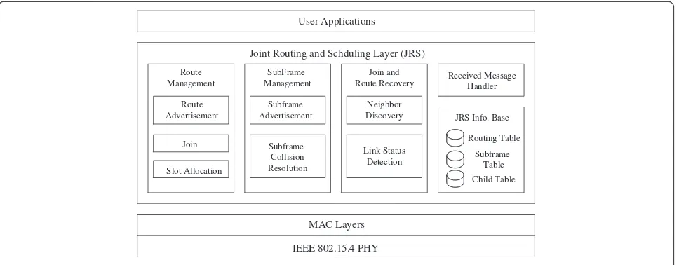
JRS operates as a network layer subsystem on the entire networking stack and interacts with neighboring layers, namely the lower MAC layer in the bottom and upper application layer on the top. The JRS subsystem jointly optimizes routing and scheduling in a multi-channel multi-hop network of the M2M domain. Figure 1 shows the JRS network architecture, which consists of the fol-lowing four function blocks: route management (RM), subframe management (SFM), join and route recovery (JRR), and received message handler (RMH).
The RM block has three main functions: first, route advertisement is for exchanging route information among the devices. Using this function, the devices can discover their neighbors. Second, join is for selecting a parent device and requesting to join it. Finally, slot allo-cationis for assigning a TDMA slot within the subframe to the children. Slot allocation is performed when a de-vice receives a join request (JREQ) from a child candi-date device. The SFM block has two main functions:
subframe advertisement is for exchanging the subframe information among the devices, by which each device can maintain channel occupancy status of its neighbors within the interference range. Subframe collision reso-lution is for avoiding the selection of a duplicate sub-frame. When two or more devices within interference range select the same subframe, this function is performed. The JRR block has two main functions:
following sections, we present detailed descriptions of each block.
3. JRS operation
In this paper, we focus on the development and imple-mentation of the unattended environmental monitor-ing M2M system, in which the end device has a stringent energy requirement. Consequently, in order to maximize the lifetime of the capillary M2M net-work, we use TDMA-based on/off scheduling as a baseline MAC scheme. Moreover, to enhance network performance and avoid collisions in the neighboring area, we also consider the use of multi-channel com-munication. As a network starts up, JRS first sets up the tree shape of routes and allocates channels and time slots needed for TDMA-based operation, using CSMA. After completing these procedures, all the devices in the network operate in TDMA mode according to their fixed schedules at the exact time. JRS basically performs the route setup and the subframe allocation. In addition, it provides the joining-support functionality for newly turned-on de-vices en route. JRS also performs route recovery when a route failure is detected. Assuming that the clocks of all the network devices are synchronized exactly (i.e., every device has to maintain the same timer), the M2M gateway starts the route setup procedure.
Figure 2 shows the overall operation of JSR. In the setup phase, all the devices in the network operate in CSMA mode using a predefined common channel and perform the route setup and subframe allocation. In the figure, the time is divided into two phases. During the setup phase, JRS establishes the route from each end device to the M2M gateway device in the
tree-topology shape. Based on the established routing path, JRS allocates a subframe to each device. After the subframe allocation is completed, each device can maintain its own subframe table for k-hop distance, which is the interference range of the device and in which the numerical value of k has to be defined through the experiment. In addition, the communica-tion between a pair of devices is always performed at the parent's subframe.
If the status of network becomes stable (i.e., the route and the subframe of each device do not change) during the setup phase, the devices in the network have to operate in TDMA mode according to the predefined active/sleep schedule (TDMA-based on/off phase). In other words, the communication schedule of all the devices including transmit, receive, and sleep is fixed. In the TDMA region, the time is divided into a large period T, and the period,T, is further divided into N
small periods, as shown in Figure 2. This small period,
T/N, is the unit of the subframe used by each device. Joint Routing and Schduling Layer (JRS)
Route Management
SubFrame Management
Join and
Route Recovery Received MessageHandler
JRS Info. Base
User Applications
MAC Layers
Route Advertisement
Join
Slot Allocation
Subframe Advertisement
Subframe Collision Resolution
Neighbor Discovery
Link Status Detection
Routing Table Subframe
Table Child Table
IEEE 802.15.4 PHY
Figure 1Network architecture of JRS.
Setup phase : CSMA mode
TDMA-based on/off phase : CSMA and TDMA hybrid mode
Superframe #1
Subframe #1
Superframe #2
T
…
…
Subframe #2 Subframe #N
T/N
As mentioned earlier, JRS maintains the four function blocks (RM, SFM, JRR, and RMH) for which various JRS control messages are exchanged among the devices. These control messages include the following: route advertisement (RADV), JREQ, join confirm (JCNF), channel advertise-ment (CADV), HELLO, route information request (RREQ), and route and subframe information request (RSREQ).
3.1 Route management
During the setup phase (operating in CSMA mode), route management is enabled. Figure 3 shows an ex-ample of route management. As a device starts up, it first runs a route advertisement (i.e., neighbor discovery) procedure to create the routing table, whose entries in-clude the device ID, destination ID (gateway device ID), next-hop ID, hop count to the gateway, and parent/child relationship. Each device maintains entries only for those neighbors within the k-hop distance (i.e., interference range). This information is used for the subsequent tree route construction. The route advertisement procedure works in a manner similar to distance vector (DV) algo-rithms in that the gateway creates the RADV message including its routing table entry and broadcasts it to each of its neighbors, and the neighbors that receive this RADV update their routing table and rebroadcast it in sequence.
To set up the shortest path to the gateway, each device in the network waits until the routing table entries become stable as this procedure is repeated. After the routing table stabilizes, the device runs join and slot allocation procedures by sending the JOIN message to the parent. When the parent receives this message, it registers a corresponding device to its child table and responds with the JCNF message. Through the JCNF message, the child device is evenly assigned with time slots within a subframe to exchange data. The time slot
structure within a subframe is described in the next subsection.
3.2 Subframe management
Route management and subframe management proce-dures are performed nearly simultaneously. In the subframe management procedure, each device in the network is assigned a channel (i.e., subframe) for com-munication between a parent–child pair. Figure 4 shows the superframe structure of the JRS framework. In the figure, the time is divided into superframes, each
superframe is divided into N subframes, and each
Gateway
1 2
3 4 5
6 7 8 9
JREQ
JCNF Gateway
1 2
3 4 5
6 7 8 9
RADV
Route Advertisement
(Neighbor Discovery) Join and Slot Allocation
Routing table is stabillized
Figure 3Example of route setup.
Setup phase
TDMA-based on/off phase
Superframe #1
Subframe #1
…
Superframe #2
Freq. index #1
Freq. index #16
Time index #1
Time index #N
TDMA time slots for DATA
Subframe #(15N)
…
…
…
…
…
…
…
Time index #2
Freq. index #2
Subframe #2 CSMA operation in Freq. index #1 (common channel)
FREE Sleep
CSMA operate in Freq. index #1 (common channel)
subframe is divided into a number of time slots. Note that this subframe should be unique within the interfer-ence range to avoid collision in the neighboring area, but the number of available physical frequencies is lim-ited by the physical layer (PHY) radio or external inter-ference sources. To resolve this problem, we employ the multi-channel communication approach to extend the number of available subframes for supporting devices within the interference range. Consequently, the sub-frame can be defined by physical frequency and time in-dices. In our work, we used the IEEE 802.15.4 PHY radio, which allows for the use of 16 channels, where (16 × N) subframes are created. Accordingly, within the interference range of a specific node, (16 ×N) nodes can be supported.
Each device in the network maintains its own frame table, whose entries include the device ID, sub-frame information (i.e., a pair of frequency index and time index), hop count, and sequence number of each device within the interference range. Each device in the network randomly selects its own subframe among the selectable subframes and then broadcasts the CADV message by one hop, periodically, which includes the subframe table information. Whenever a device receives a CADV message, the device updates its subframe table. At this time, the device checks whether its subframe has been duplicated in another device. If it has been dupli-cated, the device with the larger ID value reselects its subframe, except for the duplicated one. This procedure continues until the subframe table of the device becomes stable. If all the entries of the subframe table do not change during a certain period of time, the device permanently sets the subframe. In the subsequent TDMA-based on/off phase, a device uses this subframe to communicate with its child devices. To communicate with its parent, a device uses its parent's subframe. Thus, a device should not have the same time index as its parent so that it can communicate with both its parent and its children.
3.3 Join and route recovery
When a new device is turned on initially, it waits for a HELLO message from neighbors. As shown in Figure 4, every device has FREE duration in its subframe. Note that the device has to operate in CSMA mode at the common physical channel and maintain active status in FREE duration. The device broadcasts a HELLO mes-sage by one hop in every FREE duration (i.e., a HELLO message is broadcasted periodically).
When the new device receives the HELLO message from a neighbor, the new device responds with the RSREQ message to ask for the route and subframe infor-mation. When the neighbor device receives the RSREQ from the new device, the neighbor device has to respond
with the message including the route and subframe information. As a result, the new device is able to obtain the neighbor's route and subframe information and update its routing/subframe tables. Upon receiving a HELLO message, the new device can obtain its neighbor's channel and route information using this procedure. After all the table entries of the new node become stable, the joining procedure of route management is performed. Likewise, the subframe management procedure can be also performed.
The route recovery procedure is the same as the join case. If a link failure notification from a lower layer arrives, the device detects a transmission error and operates like a new node. However, in this case, because the device already knows its neighbor's subframe occu-pation state, it requests only the route information with the RREQ message, except for the subframe information.
4. Prototype implementation
4.1 Implementation
In this section, we present the implementation for the proposed framework. As shown in Figure 5, we devel-oped the hardware prototype of M2M mote device and debugging board according to IEEE 802.15.4, which is considered a major technical candidate for capillary M2M networks. The device has a connector to extend the sensing modules, and it is composed of the Chipcon CC2420 RF chip [32] and the Texas Instruments MSP430 microcontroller (Dallas, Texas, USA) [33]. The CC2420 chip has a maximum data transmit rate of 250 Kbps and a receiver sensitivity of−95 dBm and operates in the 2.4-GHz bandwidth. Built on a 16-bit RISC CPU, the MSP430 has a 12-bit A/D converter. In addition, this 60 × 32-mm2device has 116 KB of flash memory and 8 KB of RAM. A full networking stack including the pro-posed JRS framework described in Section 2 is implemented using nesC and the TinyOS 2.0 operating systems. Table 1 provides details about the hardware specification.
purpose of fire surveillance. A temperature sensor is at-tached to each device in the testbed. In our demonstra-tion, when the temperature sensed at a device rises above a specific point, the sensing data are forwarded to the M2M gateway device, which then sends a notifica-tion about this event to a mobile phone through a don-gle device. Then, we can observe the burning position
on the three-dimensional visualization application of the mobile phone.
4.2 Experiment and performance evaluation
For the purpose of comparison, we also implemented a tree routing of ZigBee [34] and unslotted CSMA MAC in TinyOS 2.0 on our mote device. We evaluated the
(a)
MCU MSP430
RF CC2420
Oscillator
Antenna
Po
w
erS
/W
S
/W
S
/W
S
/W
LED LED LED LED
L
E
Do
h
m
Cry
sta
l
Regulator
j1 j2 ext1 ext2
+
(b)
Figure 5Hardware prototype.(a) IEEE 802.15.4-based device and debugging board. (b) Device layout (head and tail).
Table 1 Hardware specification
General Features
Board size 60 × 32 (mm2)
operating system TinyOS 2.0
Processor Product number MSP430FG4618 (Texas Instruments)
Memory 116 KB of flash memory
8 KB of SRAM
Miscellaneous 12-bit A/D, D/A converter
Radio Product number CC2420 (Texas Instruments)
Frequency range 2400 to approximately 2483.5 (MHz)
Transmit data rate 250 Kbps (Max.)
Transmit power 0 dBm
Receiver sensitivity −95 dBm
Antenna Chip antenna
Miscellaneous Temperature sensor LM35DZ (NS)
Current consumption 28 mA @ RF mode
470μA @ Idle mode
Power supply 1.5-V Alkaline battery (×2) (AA Size)
performance in terms of the following three metrics: the average packet reception rate, average per-hop delivery latency, and energy efficiency. For fair comparison in the experiments of the packet reception rate and the per-hop delivery latency, we did not use the CSMA duty cyc-ling; that is, all the devices operate in always-on status. In the experiments, we constructed a network topology consisting of 15 devices (Figure 7), in which all the de-vices except for the M2M gateway are data sources and
the packets of 127 bytes are sent toward the
predesignated M2M gateway. We controlled the packet generation rate (i.e., packets per device per second) to vary the traffic load in the network. We repeated each
experiment 20 times to collect enough data for statistical confidence.
Figure 8 shows the average packet reception rate with increasing packet generation rate. Overall, JRS exhibits a significantly higher packet reception rate than the ZigBee tree routing. Under low traffic conditions (i.e., packet generation rate <2.0), both JRS and ZigBee achieved good reception rates. However, as the packet generation rate increases, the reception rate of ZigBee sharply deceases because of the high contention over-head of CSMA. In contrast, JRS maintains a high recep-tion rate even under high traffic condirecep-tions.
We measured the average per-hop delivery latency with increasing packet generation rate (Figure 9). In the figure, the latency of ZigBee quickly increases as the traffic load increases. The reason is that the CSMA transmission of ZigBee requires a longer back-off time Figure 6Miniature testbed setup.(a) Miniature testbed for a building fire-alarm system. (b) Mobile phone and dongle device for collecting data. (c) Three-dimensional visualization application of the miniature testbed on a mobile phone.
B
7
6
1
F
A
5
D
8
3
E
9
4
2
C
Gateway
Terminal (Dongle device)
Figure 7Network topology for demonstration and experiments.
0 0.5 1 1.5 2 2.5 3 3.5 4 4.5 5 0
10 20 30 40 50 60 70 80 90 100
Packet generation rate (packets/device/sec)
Average packet reception rate (%)
JRS ZigBee
for resolving collisions under high traffic conditions. On the other hand, JRS uses TDMA transmission for data delivery, which does not require an additional waiting time such as random back-off. Moreover, JRS provides the scheduled concurrent transmissions of adjacent devices through a multi-channel approach, and thus, is able to maintain a certain level of per-hop latency even under heavy traffic conditions.
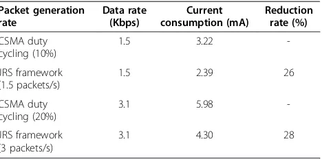
In the third experiment, we used the CSMA duty cyc-ling on the ZigBee, which is being considered as a gen-eral solution for extending network lifetime, for the energy efficiency comparison. In this experiment, the measured values for the RF active current, idle current, and active time per packet are 28 mA, 470μA, and 46.4 ms, respectively. The results of this experiment are shown in Table 2. From the results, we can observe that the proposed framework exhibits more energy efficiency on average by 26%.
In the existing CSMA duty-cycling approach, each device in the network has to wait for back-off time be-fore transmitting its pending packets to avoid collision with neighbor devices. Moreover, the transceiver of each device has to maintain active status during the fixed portion of the beacon interval according to the
predefined duty-cycling rate. This approach causes an increase in latency under heavy traffic conditions and suffers from unnecessary energy waste caused by the relatively long active duration under light traffic condi-tions. On the other hand, in the proposed framework, the transceiver of each device remains active only when it has pending packets or is receiving data. In addition, there is no additional delay by the random back-off. In other words, the proposed framework could be an optimal solution to extend network life-time under various traffic conditions.
5. Conclusion
JRS is a joint routing and scheduling framework for ca-pillary M2M networks. To achieve the conflicting goals of maximizing network performance and conserving energy, JRS has the following important features: (1) CSMA-TDMA hybrid MAC approach to combine the strengths of both types of MAC protocols while offset-ting their shortcomings; (2) integrated rouoffset-ting and MAC scheduling to minimize the protocol overhead, for which JRS organizes the multi-hop tree network through a route management procedure and assigns the subframe to each end device in a distributed manner; and (3) multi-channel communication to extend the number of subframes and enhance network performance. Experimental results with the prototype implementation demonstrate that JRS outperforms con-ventional schemes, even under heavy traffic conditions.
Competing interests
The authors declare that they have no competing interests.
Authors' information
TS received his Ph.D. degree in Information Security from Korea University, Seoul, Korea and his M.S. and B.S. degrees in Computer Engineering from Ajou University, Suwon, Korea. From August 2005 to February 2011, he was with the Samsung Electronics of Korea. Since 2011, he has been a professor at the Division of Information and Computer Engineering, Ajou University, Suwon, Korea. His research interests include convergence platform security, mobile cloud computing security, mobile/wireless network security, WPAN/ WSN security, anomaly detection algorithms, and machine learning applications.
HHC received his B.S., M.S., and Ph.D. degrees in Computer Science and Engineering from Sogang University, Seoul, Korea in 1994, 1996, and 2005, respectively. From 2005 to 2008, he was with the Samsung Electronics of Korea. Since 2009, he has been a professor at the Department of Computer Science, Inha Technical College, Incheon, Korea. His research interests include wireless sensor network, ubiquitous computing, and wireless mesh routing protocol.
EJK received his B.S., M.S., and Ph.D. degrees in Electronics and Computer Engineering from Korea University, Seoul, Korea in 2004, 2006, and 2013, respectively. From September 2005 to December 2005, he was with the Next Generation Wireless Communication (NGWC) Lab., Intel Korea R&D Center at Intel Corporation. From February 2006 to July 2009, he was with the Digital Media & Communications (DMC) R&D Center at Samsung Electronics Co., Ltd. of Korea. Since August 2009, he has been with the Advanced Institute of Technology at KT Corporation, where he is currently a senior researcher. His research interests include wireless/mobile networks with an emphasis on QoS guarantee and adaptation, wireless sensor networks, wireless LAN/MAN/
0 0.5 1 1.5 2 2.5 3 3.5 4 4.5 5
Packet generation rate (packets/device/sec)
Average per-hop delivery latency (sec)
JRS ZigBee
Figure 9Average per-hop delivery latency.
Table 2 Energy efficiency comparisons
PAN, next-generation mobile networks, and machine-to-machine communications.
Acknowledgment
This research was supported by Basic Science Research Program through the National Research Foundation of Korea (NRF) funded by the Ministry of Education, Science and Technology (no. 2012R1A1A1010667).
Author details
1Division of Information and Computer Engineering, Ajou University, Suwon 443-749, South Korea.2Department of Computer Science, Inha Technical College, Incheon 402-752, South Korea.3Advanced Institute of Technology, KT Corporation, Umyeon-dong, Seocho-gu, Seoul 137-792, South Korea.
Received: 26 January 2013 Accepted: 22 April 2013 Published: 10 May 2013
References
1. D Niyato, L Xiao, P Wang, Machine-to-machine communications for home energy management system in smart grid. IEEE Commun. Mag.
49(4), 53–59 (2011)
2. R Lu, X Li, X Liang, X Shen, X Lin, GRS: the green, reliability, and security of emerging machine to machine communications. IEEE Commun. Mag.
49(4), 28–35 (2011)
3. Y Zhang, R Yu, S Xie, W Yao, Y Xiao, M Guizani, Home M2M networks: architectures, standards, and QoS improvement. IEEE Commun. Mag.
49(4), 44–52 (2011)
4. ZM Fadlullah, MM Fouda, N Kato, A Takeuchi, N Iwasaki, Y Nozaki, Toward intelligent machine-to-machine communications in smart grid. IEEE Commun. Mag.49(4), 60–65 (2011)
5. G Wu, S Talwar, K Johnsson, N Himayat, KD Johnson, M2M: from mobile to embedded internet. IEEE Commun. Mag.49(4), 36–43 (2011)
6. S-Y Lien, K-C Chen, Y Lin, Toward ubiquitous massive accesses in 3GPP machine-to-machine communications. IEEE Commun. Mag.49(4), 66–74 (2011)
7. K Chang, A Soong, M Tseng, Z Xiang, Global wireless machine-to-machine standardization. IEEE Internet Comput.15(2), 64–69 (2011)
8. Y Katsuhiko, S Hirohisa, Trends in M2M standardization and NEC’s activities to promote the standardization of remote management technologies. NEC Tech. J.6(4), 28–32 (2011)
9. ETSI TS 102 690 v2.0.6, ETSI technical specification, machine-to-machine communications (M2M); functional architecture, 2012. http://portal.etsi.org 10. EJ Kim, S Youm, Machine-to-machine platform architecture for horizontal service integration. EURASIP Journal on Wireless Communications and Networking2013(79), 1–9 (2013)
11. IEEE Std 802.15.4 2006, Wireless medium access control and physical layer specifications for low-rate wireless personal area networks. IEEE Computer Society (2006). http://ieeexplore.ieee.org
12. W Ye, J Heidemann, D Estrin, An energy-efficient MAC protocol for wireless sensor networks, inProceedings of the 21st Annual Joint Conference of the IEEE Computer and Communications Societies INFOCOM’02(IEEE, Washington, 2002, New York, 2002), pp. 1567–1576
13. TV Dam, K Langendoen, An adaptive energy-efficient MAC protocol for wireless sensor networks, inProceedings of the 1st International Conference on Embedded Networked Sensor Systems SenSys’03(ACM, New York, 2003, Los Angeles, 2003), pp. 171–180
14. J Hill, D Culler, Mica: a wireless platform for deeply embedded networks. IEEE Micro22(6), 12–24 (2002)
15. AE Hoiydi, J-D Decotignie, MAC Wise, An ultra low power MAC protocol for multi-hop wireless sensor networks, inProceedings of the 1st International Workshop on Algorithmic Aspects of Wireless Sensor Networks
ALGOSENSORS’04(ACM, New York, 2004, Turku, 2004), pp. 18–31 16. J Polastre, J Hill, D Culler, Versatile low power media access for wireless
sensor networks, inProceedings of the 2nd International Conference on Embedded Networked Sensor Systems SenSys’04(ACM, New York, 2004, Baltimore, 2004), pp. 95–107
17. M Buettner, GV Yee, E Anderson, R Han, X-MAC: a short preamble MAC protocol for duty-cycled wireless sensor networks, inProceedings of the 4th International Conference on Embedded Networked Sensor Systems SenSys’06
(ACM, New York, 2003, Boulder, 2006), pp. 307–320
18. SC Ergen, P Varaiya, PEDAMACS: power efficient and delay aware medium access protocol for sensor networks. IEEE Trans. Mobile Comput5(7), 920–930 (2006)
19. LV Hoesel, P Havinga, A Lightweight Medium Access Protocol (LMAC) for Wireless Sensor Networks: Reducing Preamble Transmissions and Transceiver State Switches, inProceeding of the 1st International Workshop on Networked Sensing Systems INSS’04(ACM, New York, 2004, 2004), pp. 205–208
20. GP Halkes, KG Langendoen, Crankshaft: an energy-efficient MAC-protocol for dense wireless sensor networks, inProceedings of the 4th European Conference on Wireless Sensor Networks EWSN’07(ACM, New York, 2009, Delft, 2007), pp. 228–244
21. W Hu, X Li, H Yousefi’zadeh, LA-MAC: a load adaptive MAC protocol for MANETs, inProceedings of the 28th IEEE Conference on Global
Telecommunications GLOBECOM’09(ACM, New York, 2009, Honolulu, 2009), pp. 1–6
22. P Bahl, R Chandra, J Dunagan, SSCH: Slotted seeded channel hopping for capacity improvement in IEEE 802.11 ad hoc wireless networks, in
Proceedings of. the 10th Annual International Conference on Mobile Computing and Networking MobiCom’04(ACM, New York, 2004, Philadelphia, 2004), pp. 216–230
23. N Jain, SR Das, A Nasipuri, A multichannel CSMA MAC protocol with receiver-based channel selection for multihop wireless networks, in
Proceedings of the 10th International Conference on Computer
Communications and Networks, IC3N’01(ACM, New York, 2001, Scottsdale, Arizona, 2001), pp. 432–439
24. A Nasipuri, J Zhuang, SR Das, A multichannel CSMA MAC protocol for multihop wireless networks, inProceeding of the IEEE Wireless Communications and Networking Conference WCNC’99(IEEE, Washington, 1999, New Orleans, 1999), pp. 1402–1406
25. A Nasipuri, SR Das, A Nasipuri, SR Das, Multichannel CSMA with signal power-based channel selection for multihop wireless networks, in
Proceedings of the 52nd Vehicular Technology Conference VTC’00(IEEE, Washington, 2000, Boston, 2000), pp. 211–218
26. J So, NH Vaidya, Multi-channel MAC for ad hoc networks: Handling multi-channel hidden terminals using a single transceiver, inProceedings of the 5th ACM International Symposium on Mobile Ad Hoc Networking and Computing MOBIHOC’04(ACM, New York, 2004, Tokyo, 2004), pp. 222–233 27. Z Tang, JJ Garcia-Luna-Aceves, Hop-Reservation Multiple Access (HRMA) for
Ad-Hoc Networks, inProceedings of the 21st Annual Joint Conference of the IEEE Computer and Communications Societies INFOCOM’99(IEEE, Washington, 1999, New York, 1999), pp. 194–201
28. S Wu, C Lin, Y Tseng, J Sheu, A new multi-channel MAC protocol with on-demand channel assignment for multi-hop mobile ad hoc networks, in
Proceedings of the 5th International Symposium on Parallel Architectures, Algorithms, and Networks I-SPAN’00(Hindawi, New York, 2000, Dallas, 2000), pp. 232–237
29. R Draves, J Padhye, B Zill, Routing in multi-radio, multi-hop wireless mesh networks, inProceedings of the 10th Annual International Conference on Mobile Computing and Networking MobiCom’04(ACM, New York, 2004, Philadelphia, 2004), pp. 114–128
30. A Raniwala, K Gopalan, T Chiueh, Centralized channel assignment and routing algorithms for multi-channel wireless mesh networks. ACM SIGMOBILE Mobile Computing and Communications Review8(2), 50–65 (2004)
31. TinyOS 2.0. http://www.tinyos.net. Accessed 7 Jan 2013
32. Chipcon, Chipcon Products from Texas Instruments. http://www.chipcon.com Accessed 7 Jan 2013
33. MSP430, Texas Instruments. http://www.ti.com. Accessed 7 Jan 2013 34. ZigBee Alliance, ZigBee Specification, Document 053474r13, 2006. http://www.
zigbee.org
doi:10.1186/1687-1499-2013-126