R E S E A R C H
Open Access
Interference cancellation for
non-orthogonal multiple access used
in future wireless mobile networks
Xin Su
1, HaiFeng Yu
2, Wansoo Kim
3, Chang Choi
4and Dongmin Choi
5*Abstract
Non-orthogonal multiple access (NOMA) is suggested as a radio access candidate for future wireless mobile networks. It utilizes the power domain for user multiplexing on the transmitter side and adopts a successive interference cancellation (SIC) as the baseline receiver scheme, considering the expected mobile device evolution in the near future. However, recent research focuses more on the performance evaluation of NOMA in context of assuming the perfect SIC at receiver side. In order to clarify the performance gap between the perfect and the practical SIC in NOMA schemes, and to examine the possibility of applying NOMA with practical SIC, this paper investigates the performance of NOMA applying multi-input multi-output (MIMO) technology with zero-forcing (ZF) and minimum mean square error (MMSE) SIC schemes. We propose an analysis on error effects of the practical SIC schemes for NOMA and in addition propose an interference-predicted minimum mean square error (IPMMSE) IC by modifying the MMSE weight factor using interference signals. According to the IPMMSE IC and analysis of IC error effect, we further suggest the remaining interference-predicted MMSE (RIPMMSE) IC to cancel the remaining interference. The simulation results show that by considering practical IC schemes, the bit error rate (BER) is degraded compared with conventional orthogonal multiple access (OMA). This validates that the proposed IC schemes, which can predict the interference signals, provide better performance compared to NOMA with conventional ZF and MMSE IC schemes.
Keywords:Non-orthogonal multiple access, Interference cancellation, Minimum mean square error, Prediction
1 Introduction
In the fourth-generation (4G) mobile communication sys-tems, such as Long-Term Evolution (LTE), WiMAX, LTE-Advanced, and V2V networks [1–3], orthogonal access based on orthogonal frequency division multiple access (OFDMA) or single carrier-frequency division multiple access (SC-FDMA) was adopted. Orthogonal access is a reasonable choice for achieving good system throughput with a simplified receiver design. However, due to the vastly increased need for high-volume services, such as image transfer, video streaming, and cloud-based services, a new mobile communications system with further en-hancement of system throughput is required for the next-generation (5G) mobile communication systems. In order to fulfill such requirements, non-orthogonal multiple
access (NOMA) with a successive interference cancellation (SIC) receiver in downlink was presented as one of several promising candidate radio access technologies [4–10]. For downlink NOMA, non-orthogonality is achieved by intro-ducing the power domain, either in time/frequency/code domains, for user multiplexing. User de-multiplexing is obtained through the allocation of a large power difference between the users on the transmitter side and the appli-cation of SIC on the receiver side. In this case, everyone can use the overall transmission bandwidth to get higher spectrum efficiency, and better user fairness can be achieved, compared with conventional orthogonal multiple access (OMA), by assigning greater power to the users under poor channel conditions. Furthermore, NOMA is suitable for the situations of massive connectivity, because it can support more simultaneous connections.
NOMA is a candidate technology for further perform-ance enhperform-ancements of LTE and LTE-Advperform-anced, and both the concept and system performance are discussed * Correspondence:[email protected]
5Division of Undeclared Majors, Chosun University, Gwangju 61452, South
Korea
Full list of author information is available at the end of the article
and analyzed, considering the perfect SIC on the re-ceiver side [11–16]. Therefore, in this paper, we exploit the system performance based on the link-level simula-tion (LLS) of NOMA with practical SIC schemes (i.e., zero-forcing [ZF] and MMSE SIC).
We analyzed the effect of the error that is caused by the interference cancellation (IC) by considering prac-tical SIC schemes for NOMA in. Based on the analysis, we propose a novel interference-predicted minimum mean square error (IPMMSE) IC scheme for NOMA downlink, which is based on MMSE criteria from pre-diction about interference signals. Moreover, based on the IPMMSE IC and the analysis of the IC error effect, we propose the remaining interference-predicted MMSE (RIPMMSE) IC to cancel the remaining interference, which can further improve the system performance. The link-level evaluation is provided, and the simulation re-sults show that by using the proposed IC schemes, the bit error rate (BER) performance is enhanced, compared with conventional IC schemes for NOMA.
The rest of the paper is organized as follows. Section 2 introduces the basics of NOMA and describes a NOMA system model with ZF and MMSE SIC schemes by using multi-input multi-output (MIMO) technology [17]. In Section 3, we compare the conventional multiple access (MA) and NOMA with the practical IC scheme and analyze the IC error effect for NOMA. Based on IC error analysis, the proposed IPMMSE IC and RIPMMSE IC schemes are described in Section 4. Finally, we con-clude this paper in Section 5.
2 System model 2.1 NOMA basics
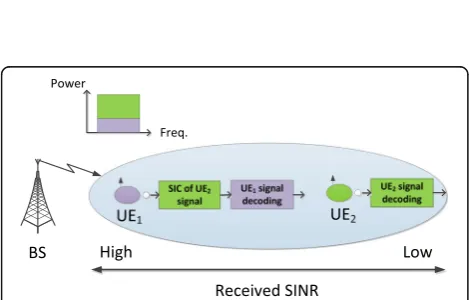
The basic NOMA scheme with SIC for a 2-user equipment (UE) case in the cellular downlink is illustrated in Fig. 1 [1]. The transmit information for UEi(i= 1, 2) at the base station (BS) issi, with transmission powerpi, so the trans-mit signal for UEiis
xi¼pffiffiffiffipisi: ð1Þ
The sum of transmit power is restricted to p. So, the transmit signals are superposed as
x¼x1þx2¼ ffiffiffiffiffip1
p s
1þ ffiffiffiffiffip2
p s
2: ð2Þ
The received signal at UEiis
yi¼hixþni; ð3Þ
wherehi is the complex channel coefficient between UEi and the BS; ni denotes the receiver’s Gaussian noise, in-cluding inter-cell interference. The power density ofni is N0,i. In the NOMA downlink, decoding is in the order of
the increasing channel gain normalized by the noise and inter-cell interference power,|hi|2/N0,i. For a 2-UE case, as
shown in Fig. 1, we assume that |h1|2/N0,1> |h2|2/N0,2, so
UE1first decodes x2and deletes its component from
re-ceived signaly1. And UE2decodesx2without interference
cancellation, because it has the first decoding order. The throughput of UEi,Riis
2.2 NOMA-MIMO with practical SIC schemes
Sets of achievable rates for NOMA have been found by Cover [18], and the proof for the optimality of the sets of achievable rates for additive white Gaussian noise broadcast channels was given by Bergmans [19]. The capacity region of the uplink fading channel with re-ceiver channel state information (CSI) was derived by Gallager [20], where he also showed that CDMA-type systems are inherently capable of higher rates than sys-tems such as slow frequency hopping that maintain or-thogonality between users. In [21], Tse gave a conclusion that NOMA is strictly better than OMA (except for the two corner points where only one user is being commu-nicated to) in terms of sum rate, i.e., for any rate pair achieved by OMA, there is a power split for which NOMA can achieve rate pairs that are strictly larger. However, this conclusion is intended for single antenna systems and Tse did not give a proof for this conclusion. Here, one should be noted that the capacity gain of NOMA over OMA is achieved at the cost of more de-coding complexity at the receivers for NOMA. The ap-plication of multiple-input multiple-output (MIMO) technologies to NOMA is important since the use of MIMO provides additional degrees of freedom for fur-ther performance improvement. The transceiver design for a special case of MIMO-NOMA downlink transmis-sion, in which each user has a single antenna and the base station has multiple antennas, has been investigated in [22] and [23]. In [24], a multiple-antenna base station
used the NOMA approach to serve two multiple-antenna users simultaneously, where the problem of throughput maximization was formulated and two algorithms were proposed to solve the optimization problem. In many practical scenarios, it is preferable to serve as many users as possible in order to reduce user latency and improve user fairness. Following this rationale, in [25], users were grouped into small-size clusters, where NOMA was im-plemented for the users within one cluster and MIMO de-tection was used to cancel inter-cluster interference. Different from conventional works, this paper focuses on the NOMA-MIMO with practical SIC instead of using perfect SIC assumption in conventional studies.
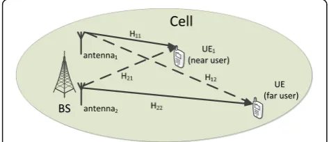
We assume orthogonal frequency division modulation (OFDM) signaling, although we consider non-orthogonal user multiplexing. Figure 2 illustrates the transmission scenario in the downlink NOMA-MIMO scheme for a 2-UE case, where 2-UE1is a cell-center user (near user) and
UE2is a cell-edge user (far user). Figure 3 shows the block
diagram of transmitter and receiver for the downlink NOMA scheme. We assume there are two transmission antennas at the BS, and each antenna transmits signal to one UE. The transmit signalxifor UEiis
xi¼pffiffiffiffipisi ; ði¼1; 2Þ; ð5Þ
wherepiis the allocated power, andsiis the transmitted data for UEi. After transmitting through a 2 × 2 channel H, as shown in Fig. 2, the 2-UE system is presented as
Y¼½x1 x2 HH11 H12 21 H22
þ½n1 n2; ð6Þ
where ni (i= 1, 2) is the receiver’s Gaussian noise for UEi. The received signalyifor UEiis represented as
yi¼Hiixiþ
X
j≠i
Hjixjþni; ð7Þ
where Hji denotes the channel between the jth antenna at the BS and the ith receiver, xj is the transmit signal for UEj, which is the interference for UEi, and ni the Gaussian noise. After reception, the signals are ranked in decreasing order by power. Channel estimation (CE)
is performed for the interference signalyjiwith powerpj> pi (power of the desired signal). Then, SIC is employed until all interference signals are cancelled. The estimated received signal ~si is obtained forUEi.For the 2-UE case, from Eq. (6), the received signals for UE1and UE2are
y1 ¼H11x1þH21x2þn1
y2 ¼H12x1þH22x2þn2; ð8Þ
respectively. Since NOMA allows UEs to share the same resources, and differentiates UE by power, IC is performed for UE with lower power to cancel the inter-user interfe-rence. Because UE2is a far user with greater power, the
elementH21x2is cancelled by the IC fromy1, whereasy2
can be demodulated directly without IC.
In this paper, we consider practical SIC schemes based on the zero-forcing (ZF) and the MMSE criteria. As de-scribed in the system model, by assuming powerp2>>p1,
the UE2can directly detect the signal without cancellation
of interference. For UE1, the received signaly1is
y1¼H11 ffiffiffiffiffip1
MMSE criteria after getting the estimated channelH~21:
^
where the sign Hin the superscript in the equation rep-resents the Hermitian transpose and σ2
n1 is the variance of noise, n1. Then, the estimated interference signal can
be obtained as
The received signal is updated by subtracting the esti-mated interference signal:
After the canceling the interference signal with high power, UE1can detect the desired information, s1, from
the updated received signal.
3 IC error analysis
3.1 Comparison between conventional MA and NOMA with practical IC scheme
In this section, we compare the packet error rate (PER) and throughput performances of conventional MA and NOMA by LLS. We still use the system model mentioned above for 2-UE. In conventional MA (without NOMA), the power for UE1(near user),p1, is assigned as 0.8, and
for UE2(far user),p2, is 0.2, which follows the water filling
(WF) algorithm. For NOMA, e.g., p1= 0.2, p2= 0.8 [4],
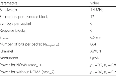
which is power control (PC). We imitate system-level simulation (SLS) by LLS, where power allocation is used instead of path loss for cases without and with NOMA (i.e., WF versus PC). According to the LTE specifications, simulation parameters are summarized in Table 1. Figure 4 shows the PER performance for cases with NOMA (case_1) and without NOMA (case_2), where the practical ZF IC is applied for UE1 in case_2. According to the PER, the
throughputCcan be calculated by
C¼ð1−PERÞ nbit=packet
Tpacketð Þs : ð
13Þ
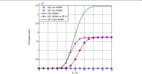
Therefore, the throughput performance for case_1 and case_2 is shown in Fig. 5. In the LLS, the path loss is not considered, and if we compare the performance between case_1 (p1= 0.2, p2= 0.8) and case_2 (p1= 0.8, p2= 0.2)
under the scenario without NOMA, the performance of UE1 in case_1 is same as UE2 in case_2. And the
per-formance of UE2in case_1 is the same as UE1in case_2.
So, it is fair to compare the scenario of case_1 (with NOMA) and case_2 (without NOMA).
From the simulation results shown in Fig. 4, we deter-mine that in NOMA, UE2 can detect information with
greater power than interference from UE1. Without
NOMA, UE2 cannot detect information owing to the
lower power compared to the interference signal from UE1. On the other hand, UE1 with NOMA can benefit
from IC, even though the power of the interference signal is much higher than the target signal. Without NOMA, UE1has performance similar to UE2with NOMA, owing
to the existing interference from the lower power user. As the results shown in Fig. 5, NOMA can increase the sum throughput and improve the fairness between the near and far users, compared with the situations without NOMA.
In order to evaluate the performance of NOMA under simulation, we provide comparisons of the LLS for UE1
under different modulation schemes, with the bound value for UE1that is obtained from Eq. (4), mentioned
above. Figure 6 shows the simulation curves for UE1
with NOMA under the perfect IC for different modula-tion and coding schemes. The coding scheme is convo-lutional code; the channel environment is single-path Rayleigh fading; and other simulation parameters are the same as in Table 1. From the comparison, all the simula-tion curves are lower than the bound and show a higher data rate with a higher order of modulation schemes. This verifies the LLS results and the analysis for the fur-ther research.
4 IC error under AWGN channel
For convenience, we use the same NOMA-MIMO trans-mission scenario as described in Section 2. At UE1(near
user), IC is applied to cancel the interference from the UE2
signal, as described in Fig. 7. Under the AWGN channel, the received signal for UE1is
y1¼x1þx2þn1; ð14Þ
and owing to the larger power ofx2compared to x1, x2
should be demodulated first. When demodulating x2at
UE1,x1becomes the interference component:
Fig. 3Block diagram of transmitter and receiver for the downlink NOMA-MIMO scheme
Table 1Simulation parameters
Parameters Value
Bandwidth 1.4 MHz
Subcarriers per resource block 12
Symbols per packet 6
Resource blocks 6
Tpacket 0.5 ms
Number of bits per packet (nbit/packet) 864
Channel AWGN
Modulation QPSK
Power for NOMA (case_1) p1= 0.2,p2= 0.8
y1¼x2þðx1þn1Þ ¼x2þi1 AWGN; ¼~yx2jUE1 ð15Þ
wherei1_AWGN is the interference for x2plus noise, and we assume that the demodulated signal of x2at UE1is
~
x2 UE1j . Then, the noise enhancement ratio when demodulatingx2at UE1is
eAWGN¼i1 AWGN
n1 : ð
16Þ
After that, x~2 UE1j is re-modulated in order to cancel
this signal from y1, and the received signal after IC for
x2is
Fig. 4PER performance with and without NOMA under AWGN channel
y′
1¼y1−^x2
¼x1þðx2−^x2Þ þn1; ð17Þ
where ^x2 is the re-modulated signal and the component
x2−x^2
ð Þis the remaining interference forx1after IC. The
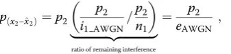
power of the remaining interference forx1is
pðx2−^x2Þ¼p2
p2
i1 AWGN=
p2
n1
|fflfflfflfflfflfflfflfflfflfflfflffl{zfflfflfflfflfflfflfflfflfflfflfflffl}
ratio of remaining interference ¼ p2
eAWGN ; ð 18Þ
wherei1 AWGNp2 is the signal-to-interference-plus-noise ratio (SINR) and p2n1 is the signal-to-noise ratio (SNR) of x2
from perfect IC. Therefore, the bound value for UE1
after practical IC ofx2is
r1IC AWGN¼ log2 1þ
p1
p2
eAWGNþn1
!
: ð19Þ
Figure 8 shows the loss due to IC error for UE1
NOMA under practical IC compared with perfect IC (Fig. 6).
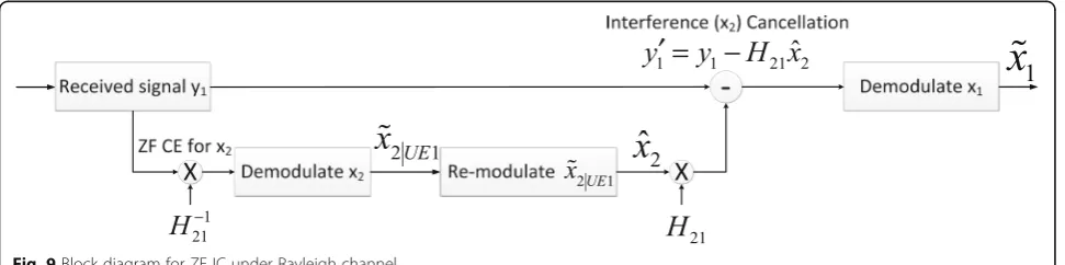
4.1 ZF IC error under single-path Rayleigh channel
Different from AWGN channel, various IC schemes can be used under the Rayleigh channel due to essentiality of chan-nel equalization (CE). Firstly, we analyze ZF IC under the single-path Rayleigh channel. Similar to the AWGN case, the ZF IC is applied to cancel the interference from the UE2
signal, as described in Fig. 9. The received signal for UE1is
y1¼H11x1þH21x2þn1; ð20Þ
whereH11andH21are the channel coefficients for x1and
x2, respectively. Due to the larger power ofx2,x2should be
demodulated first. When demodulating x2 at UE1, H11x1
becomes the interference. After (perfect) ZF CE forx2,
Fig. 6Bound and simulation curves for UE1under NOMA with different modulation schemes
H−1
21y1¼H−211H11x1þx2þH−211n1 ¼x2þH−211ðH11x1þn1Þ ; ¼x2þi1 ZF
¼~yx2jUE1
ð21Þ
where i1_ZF is the interference for x2 plus noise, we
as-sume the demodulated signal of x2 at UE1 is x~2 UE1j . Then, the noise enhancement ratio when demodulating x2at UE1is
eZF¼i1 ZFn
1 : ð
22Þ
After that,~x2 UE1j is re-modulated and then multiplied by
the channel coefficientH21to cancel this signal fromy1.
The received signal after ZF IC forx2is
y′
1 ¼y1−H21^x2
¼H11x1þH21ðx2−x^2Þ þn1 ; ð 23Þ
where^x2 is the re-modulated signal and the component
H21ðx2−x^2Þ is the remaining interference forx1after ZF
IC. The power of the remaining interference forx1is
pðx2−^x2Þ¼p2
p2jH21j2
i1 ZF =
p2jH21j2
n1
!
|fflfflfflfflfflfflfflfflfflfflfflfflfflfflfflfflfflffl{zfflfflfflfflfflfflfflfflfflfflfflfflfflfflfflfflfflffl}
ratio of remaining interference
¼p2jH21j2
eZF ;
ð24Þ
where p2i1jH21j2
ZF is the SINR and p2jH21j2
n1 is the SNR of x2
from perfect IC. Therefore, the bound value for UE1
after ZF IC ofx2is
Fig. 8Bound for UE1NOMA with perfect and practical IC under AWGN channel
r1 IC ZF¼ log2 1þ
p1jH11j2
p2jH21j2
eZF þn1
0 @
1
A: ð25Þ
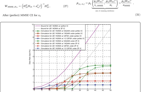
Figure 10 shows the bound and simulation curves for UE1NOMA with perfect and practical ZF IC under the
single-path Rayleigh channel. From the figure, both bound and simulation curves show the loss due to the practical IC error, compared with perfect IC.
4.2 MMSE IC error under single-path Rayleigh channel
Similar to ZF IC analysis, we analyze MMSE IC under the single-path Rayleigh channel. At UE1, the MMSE IC
is applied to cancel the interference from the UE2signal,
as described in Fig. 11. The received signal for UE1is
y1¼H11x1þH21x2þn1; ð26Þ
where H11 and H21 are the channel coefficients for x1
and x2, respectively. Due to the greater power of x2, x2
should be demodulated first. When demodulating x2at
UE1,H11x1becomes the interference. We assume perfect
channel estimation, so the MMSE weight factor for channelH21is
WMMSE H21 ¼ H
H
21H21þσ2n1I
−1
HH
21; ð27Þ
After (perfect) MMSE CE forx2
WMMSEH21y1¼WMMSEH21H11x1þx2þWMMSEH21n1
¼x2þWMMSEH21ðH11x1þn1Þ ;
¼x2þi1 MMSE
¼~yx2jUE1
ð28Þ
where i1_MMSE is the interference for x2 plus noise, we
assume the demodulated signal of x2 at UE1 is ~x2 UE1j . Then, the noise enhancement ratio when demodulating x2at UE1is
eMMSE¼i1 MMSE
n1 ; ð
29Þ
After that, ~x2 UE1j is re-modulated, then multiplied by
the channel coefficientH21to cancel this signal fromy1.
The received signal after MMSE IC forx2is
y′
1 ¼y1−H21^x2
¼H11x1þH21ðx2−x^2Þ þn1; ð 30Þ
where x^2 is the re-modulated signal and the
compo-nent H21ðx2−^x2Þ is the remaining interference for x1
after MMSE IC. The power of the remaining interfer-ence for x1 is
pðx2−^x2Þ¼p2
p2jH21j2
i1 MMSE =
p2jH21j2
n1
!
|fflfflfflfflfflfflfflfflfflfflfflfflfflfflfflfflfflffl{zfflfflfflfflfflfflfflfflfflfflfflfflfflfflfflfflfflffl}
ratio of remaining interference
¼p2jH21j2
eMMSE ;
ð31Þ
where p2jH21j 2
i1 MMSE is the SINR and p2jH21j 2
n1 is the SNR of x2
from perfect IC. Therefore, the bound value for UE1
after MMSE IC ofx2is
r1 IC MMSE¼ log2 1þ
p1jH11j2
p2jH21j2
eMMSE þn1
0 @
1
A : ð32Þ
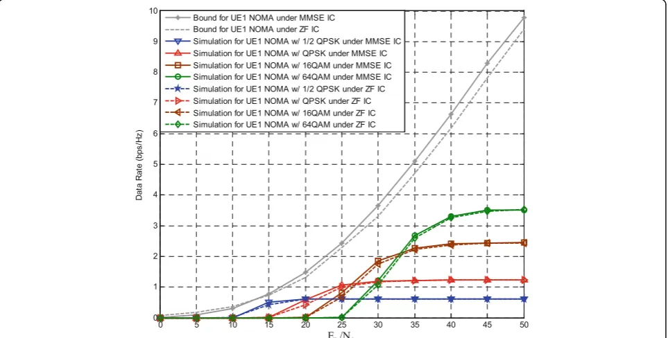
Figure 12 shows the bound and simulation curves for UE1NOMA with practical ZF and MMSE IC under the
single-path Rayleigh channel. From the simulation re-sults, both bound and simulation curves show the gain from MMSE IC compared with ZF IC.
5 Proposed interference-predicted MMSE IC schemes for NOMA
5.1 Proposed interference-predicted MMSE IC scheme
Based on the analysis of MMSE IC in the previous section, we propose modifying the MMSE weight
factor by introducing the information on interfer-ence signals to improve the link-level performance of NOMA. From Eq. (28), we can determine that the interference for x2 plus noise after MMSE CE
for x2 is
i1 MMSE¼WMMSE H21ðH11x1þn1Þ: ð33Þ
We assume that i1_MMSE is the background noise
for demodulating x2, so then, the IPMMSE weight
factor is
WIPMMSE H21¼ H
H
21H21þσ2i1 MMSEI
−1
HH
21; ð34Þ
whereσ2
i1 MMSE is obtained from the variance ofi1_MMSE :
Fig. 11Block diagram for MMSE IC under Rayleigh channel
varði1 MMSEÞ ¼E i1 MMSEiH1 MMSE
where the notation E represents estimation. After de-riving Eq. (35), we find that the MMSE weight factor can be modified by considering interference, which makes this algorithm practical. Equation (28) can be replaced by
Figure 13 shows the BER curves for UE1with
conven-tional OMA and NOMA for different IC schemes under single-path Rayleigh fading channel. The modulation and coding scheme used in the simulation is quadrature phase-shift keying (QPSK) with 1/2 convolutional code. From the simulation results, we find that OMA has the best BER performance, because there is no interference for OMA signaling. As for NOMA, ZF IC gives the
worst BER, but it has the lowest complexity. And MMSE IC shows the better BER performance than ZF IC, which is in accordance with our previous analysis in Section 3. Finally, the proposed IPMMSE IC gives the best BER performance among the NOMA IC schemes, because it considers the effect of the interference signals. When the target BER is 10−3, the IPMMSE IC scheme outper-forms the ZF IC scheme by around 1 dB and by 0.2 dB over the MMSE IC scheme.
5.2 Proposed remaining interference-predicted MMSE IC scheme
Based on the analysis of the IC error effect in the previ-ous section, after IPMMSE CE, the noise enhancement ratio when demodulatingx2at UE1is
eIPMMSE¼i1 IPMMSEn
1 : ð
37Þ
Then, the power of the remaining interference forx1is
pH21ðx2−^x2ÞIPMMSE¼p2jH21j
from perfect IC. The next step is to demodulate x1,
so we propose the remaining interference-predicted MMSE (RIPMMSE) IC for x1 to cancel the remaining
interference. The RIPMMSE weight factor for channel H11 is
WRIPMMSEH11¼ HH11H11þσi1 IPMMSEþn 2I
−1
HH
11; ð39Þ where σi1 IPMMSEþn2 is obtained from the variance of the remaining interference plus noise
varðH21ðx2−^x2Þ þn1Þ ¼E Hð 21ðx2−^x2Þ þn1ÞðH21ðx2−^x2Þ þn1ÞH
h i
¼E½ðH21ðx2−^x2Þ þn1Þððx2−^x2ÞHHH21þnH1Þ
¼E H21ðx2−^x2Þðx2−^x2ÞHHH21
h i
þE n1nH1
:
¼H21E xð 2−^x2Þðx2−^x2ÞH
h i
HH 21þσ2n1
¼H21pH21ðx2−^x2ÞIPMMSEH H 21þσ2n1
ð40Þ
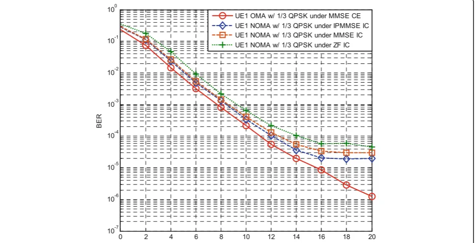
After deriving Eq. (40), we find that the MMSE weight factor can be updated by considering the power of the remaining interference, which makes this algorithm practical. Figure 14 shows the BER performances for UE1 under conventional OMA and NOMA with
differ-ent IC schemes under single-path Rayleigh fading chan-nel. The modulation and coding scheme used in the simulation is QPSK with 1/3 convolutional code. The simulation results show that RIPMMSE IC can further improve the BER performance compared to IPMMSE IC for NOMA. When the target BER is 10−3, the RIPMMSE IC scheme can provide a 1.5-dB gain, compared to the ZF IC scheme, and a 0.5 dB gain over the MMSE IC
scheme. Under the same principle, for 3-UE NOMA, the MMSE weight factor can be updated for a third time to further improve the BER performance.
6 Conclusions
In this paper, we exploit the performance of a NOMA-MIMO system for the perfect and the prac-tical SIC schemes, which clarifies the necessity for the investigation into IC schemes for NOMA. Because many previous works focused on NOMA, some of the research topics, such as employment of the prac-tical SIC and the error effect due to IC, are still in the early stages or not fully developed. In this paper, we perform the error analysis considering ZF and MMSE SIC schemes for NOMA; and based on the analysis, we propose a novel IPMMSE IC scheme by predicting the MMSE weight factor using information about interference signals. In addition, based on the IPMMSE IC scheme and the analysis of the IC error effect, we propose RIPMMSE IC to further boosts the system performance. We provide the link-level evalua-tions for a 2-UE scenario under NOMA-MIMO sys-tem on the single-path Rayleigh channel, and the simulation results show that the RIPMMSE IC scheme outperforms ZF and MMSE IC schemes by around 1.5 and 0.5 dB, respectively, at a target BER of 10−3. In the future work, a more general case, i.e., larger number of users will be examined with our proposed schemes.
Acknowledgements
This work was supported in part by Fundamental Research Funds for the Central Universities under Grant 2015B30614, in part by the Natural Science Foundation of Jiangsu Province under Grant BK20160287, and in part by the National Research Foundation of Korea (NRF) grant funded by the Korea government (Ministry of Science, ICT and Future Planning) (No. NRF-2015R1C1A1A01053301).
Competing interests
The authors declare that they have no competing interests.
Author details 1
College of IoT Engineering, Changzhou Key Laboratory of Robotics and Intelligent Technology, Hohai University, Changzhou, China.2Carrier BG,
Cloud Core Network Design and Bidding Department, Huawei Technologies CO., LTD, Shenzhen, China.3Korea Institute for Curriculum and Evaluation,
Seoul, South Korea.4Department of Computer Engineering, Chosun University, Gwangju 61452, South Korea.5Division of Undeclared Majors,
Chosun University, Gwangju 61452, South Korea.
Received: 30 June 2016 Accepted: 15 September 2016
References
1. K Maxim, C Andrey, P Anton, K Igor, Technique of data visualization: example of network topology display for security monitoring. Journal of Wireless Mobile Networks, Ubiquitous Computing, and Dependable Applications (JoWUA)7(1), 79–96 (2016)
2. B Bharat, AM Johnson, M Gisele Izera, A Pelin, A systematic approach for attack analysis and mitigation in V2V networks. Journal of Wireless Mobile Networks, Ubiquitous Computing, and Dependable Applications (JoWUA) 7(1), 97–117 (2016)
3. U Kim, J Kim, Research on object-oriented relational database model and its utilization for dynamic geo-spatial service through next generation ship navigation system, IT Convergence Practice1(2), 1–10 (2013) 4. Y. Saito, Y. Kishiyama, A. Benjebbour, T. Nakamura, A. Li, and K. Higuchi,
Non-orthogonal multiple access (NOMA) for cellular future radio access,in
Proc. of IEEE VTC-Spring, 2013, pp. 1-5.
5. Umehara, and Y. Kishiyama, Enhancing user fairness in
non-orthogonalaccess with successive interference cancellation for cellular downlink,in Proc. of IEEE ICCS, 2012, 324-328
6. K. Beomju, Non-orthogonal multiple access in a downlink multiuser beamforming system,in Proc. of IEEE MILCOM, 2013, 1278-1283.
7. A. Benjebbour, System-level performance of downlink NOMA for future LTE enhancements,in Proc. of IEEE GC Workshop, 2013, 66-70
8. L Dai, B Wang, Y Yuan, S Han, I Chih-Lin, Z Wang, Non-orthogonal multiple access for 5G: solutions, challenges, opportunities, and future research trends. IEEE Communications Magzine53(9), 74–81 (2015)
9. B. Wang, K. Wang, Z. Lu, T. Xie, and J. Quan, Comparison study of non-orthogonal multiple access schemes for 5G, in Proc. IEEE International Symposium on BMSB, 2015, 1-5
10. A Kitana, I Traore, I Woungang, Impact study of a mobile botnet over LTE networks. J Internet Serv Info Sec6(2), 1–22 (2016)
11. N. Otao, Y. Kishiyama, and K. Higuchi, Performance of nonorthogonal access with SIC in cellular downlink using proportional fairbased resource allocation,in Proc. of IEEE ISWCS, 2012, 476-480
12. Q. Liu, B. Hui, and K.H. Chang, A survey on non-orthogonal multiple access schemes,in Proc. of KICS Winter Conf., 2014, 98-101.
13. A. Benjebbour, A. Li, Y. Saito, Y. Kishiyama, A. Harada, and T. Nakamura, System-level performance of downlink NOMA for future LTE enhancements,
in Proc. of IEEE Globecom, 2013, 66-70
14. Saito, A. Benjebbour, Y. Kishiyama, and T. Nakamura, System-level performance of downlink non-orthogonal multiple access (noma) under various environments,in Proc. of IEEE VTC, 2015, 1-5
15. T. Seyama and H. Seki, Efficient selection of user sets for downlink non-orthogonal multiple access,in Proc. of IEEE PIMRC, 2015, 1062-1066 16. M.R. Hojeij, J. Farah, C.A. Nour, and C. Douillard, Resource allocation in
downlink non-orthogonal multiple access (NOMA) for future radio access.in
Proc. of IEEE VTC-Spring, 2015, 1-6
17. X Liu, H Miao, X Huang, A novel approach for blind estimation of a MIMO channel including phase unwrapping ambiguity elimination. IT Convergence Practice1(2), 20–33 (2013)
18. TM Cover, Broadcast channels. IEEE Trans. Inf. Theory18(1), 2–14 (1972) 19. PP Bergmans, A simple converse for broadcast channels with additive white
Gaussian noise. IEEE Trans. Inf. Theory20(2), 279–280 (1974)
20. RG Gallager, An inequality on the capacity region of multiaccess multipath channels, inCommunications and Cryptography: Two Sides of One Tapestry
(Kluwer, Boston, 1994), pp. 129–139
21. D. Tse and P. Viswanath, Fundamentals of wireless communication. Cambridge, Cambridge Univ. Press, 2005, ch. 6.
22. J Choi, Minimum power multicast beamforming with superposition coding for multiresolution broadcast and application to NOMA systems. IEEE Trans. Commun.63(3), 791–800 (2015)
23. MF Hanif, Z Ding, T Ratnarajah, GK Karagiannidis, A minorization-maximization method for optimizing sum rate in nonorthogonal multiple access systems. IEEE Trans. Signal Process64(1), 76–88 (2006)
24. Q Sun, S Han, I C-L, Z Pan, On the ergodic capacity of MIMO NOMA systems. IEEE Wireless Commun. Lett.4(4), 405–408 (2015)
25. Z Ding, F Adachi, HV Poor, The application of MIMO to nonorthogonal multiple access. IEEE Trans. Wireless Commun.15(1), 537–552 (2016)
Submit your manuscript to a
journal and benefi t from:
7Convenient online submission
7Rigorous peer review
7Immediate publication on acceptance
7Open access: articles freely available online
7High visibility within the fi eld
7Retaining the copyright to your article