Volume 2009, Article ID 909075,14pages doi:10.1155/2009/909075
Research Article
Multiple CFOs in OFDM-SDMA Uplink: Interference
Analysis and Compensation
Malte Schellmann and Volker Jungnickel
Fraunhofer Institute for Telecommunications, Heinrich-Hertz-Institut, Einsteinufer 37, 10587 Berlin, Germany
Correspondence should be addressed to Malte Schellmann,[email protected]
Received 1 July 2008; Revised 14 November 2008; Accepted 11 March 2009
Recommended by Erdal Panayirci
In OFDM-based space division multiple access (SDMA) systems, multiple users are served by a multiantenna base station simultaneously on the same frequency resources. In the uplink, each user’s signal may be distorted by an independent carrier frequency offset (CFO), which impairs the orthogonality of the subcarrier signals and, if not properly compensated, results in performance degradations. We analyze the influence of multiusers’ CFOs on the signal transmission in the OFDM-SDMA uplink and derive suitable bounds for the achievable signal-to-interference conditions. By modifying the signal model suitably, we develop a simple scheme for partial compensation of the CFO distortions. It allows to maintain the subcarrier-wise channel equalization and thus is well suited to be applied for a real-time system implementation. However, as CFOs impair the cyclic structure of the OFDM symbols, our scheme is not able to compensate for the entire distortion. The remaining interference is treated as additional noise, which limits the supported size of the CFOs.
Copyright © 2009 M. Schellmann and V. Jungnickel. This is an open access article distributed under the Creative Commons Attribution License, which permits unrestricted use, distribution, and reproduction in any medium, provided the original work is properly cited.
1. Introduction
A promising solution to lead wireless communication sys-tems toward high spectral efficiencies is the combination of the orthogonal frequency division multiplexing (OFDM) together with the space-division multiple access (SDMA) technique [1]. In the SDMA uplink, multiple users commu-nicate simultaneously with a multiantenna base station (BS) on the same frequency resources by transmitting their signals on different spatial layers. OFDM is a favored technique for the transmission in frequency-selective channels, as it facilitates the equalization process while at the same time enabling high spectral efficiencies. However, one of its deficiencies is its high sensitivity towards time-variant distortions. In general, these destroy the orthogonality of the single subcarrier signals and give rise to the so-called inter-carrier interference (ICI), limiting the achievable system performance [2,3]. One source for time-variant distortions is the carrier frequency offset (CFO), owing to a mismatch between the oscillators at the transmitter and receiver sides. While estimation and compensation of CFO distortions in
a single user link are fairly easy and conveniently solved [4–
6], coping with different CFOs from multiple users in any OFDM-based multiuser uplink is much more challenging, as all CFOs need to be estimated independently, and the conventional techniques for compensation do not apply.
occur before the CFOs are properly compensated. There also exist some proposals for CFO compensation to be carried out directly at the receiver by adequate signal processing. These approaches are either based on the inversion of a high dimensional matrix representing the ICI-affected channel for a complete OFDMA symbol [18,19], or they make use of successive interference cancelation techniques [20], which may be performed in an iterative fashion [21]. Unfortunately, all these approaches result in a significant increase of compu-tational complexity compared to common OFDM process-ing, whose favorable property is to enable an independent subcarrier-wise processing. Although the complexity of the aforementioned approaches based on matrix inversion can be further reduced if specific properties of the signal model are exploited [15,22, 23], it still remains considerable. A suboptimum solution maintaining the subcarrier-wise signal processing at the receiver is presented in [24]. The user signals are separated first, whereafter they are individually compensated for their user-specific CFO. Although not all ICI can be removed, a satisfactory performance is achieved if the CFOs do not become too large.
The major difference in OFDM-SDMA systems is that the channel is enhanced by a spatial dimension. To separate the users’ signals, knowledge of the SDMA channel per subcar-rier is required. With CFO distortions present, solutions to estimate the SDMA channel have been proposed in [25,26]; joint estimation of SDMA channels and the users’ CFOs can be found in [27–29]. Contributions [26, 28] also provide approaches to compensate for the CFO distortions at the receiver, which, however, have complexity demands that are similar to the OFDMA techniques mentioned earlier.
The work in this paper was motivated by seeking for a simple receiver-based CFO compensation method for the uplink of an OFDM-SDMA system. Hereby, the subcarrier-wise channel equalization is supposed to be maintained to facilitate implementation in a real-time system. Therefore, we resort to the basic idea from [24] and develop a system concept where the user signals are first separated by common OFDM-SDMA equalization and compensated for their individual CFO distortions afterwards. As this approach is clearly suboptimum, the major focus of our work lies in the proper analysis of the achievable signal conditions with respect to the amount of interference that remains in the system after such compensation. In particular, we derive closed-form expressions characterizing the bounds for the signal-to-interference ratio (SIR) before and after CFO compensation, which are verified by numerical bit-error rate analysis. This way, we obtain insights into the suitability of the approach and reveal the limits of its application range.
Based on our results, it turns out that the proposed CFO compensation concept operates conveniently only if the size of the CFOs present in the system can be kept below a few percent of the subcarrier spacing. Therefore, the approach has to be seen as a technique for fine-synchronization. Correspondingly, a coarse-frequency synchronization of all users’ signals has to be ensured. This coarse synchronization can be achieved by a frequency-advance, where terminals precompensate their signals with the CFO estimated in the downlink phase. The concept of frequency-advance
was recently realized in a practical system, as reported in [30]. In [31], we already presented the basic idea of this work and initial analytical results. Here we extend the analysis to support linear receivers providing spatial diversity gains, add the case of noncompensated CFOs for illustrative comparison and provide a refined update of the CFO compensation process to be carried out in frequency domain, which facilitates implementation.
The paper is structured as follows:Section 2introduces the OFDM signal model based on vector notation. As a preparation for analysis of the OFDM-SDMA system, we determine the SIR conditions for a single antenna OFDM link inSection 3. Hereafter, the model is modified to form the basis for the simplified CFO compensation process in OFDM-SDMA systems. In Section 4, we analyze the SIR conditions in the OFDM-SDMA system and derive bounds for the two cases where CFOs are compensated according to the proposed scheme and where they are not. These bounds are verified by simulation results inSection 5.
2. Signal Model
Notation. We use bold capital letters to denote matrices and bold letters for vectors. Scalars are written in italics. (·)H and (·)∗denote conjugate transpose and conjugate operator, respectively. tr(·) refers to the trace operator. diag(x) represents a diagonal matrix, whose diagonal is constituted of vectorx.E{·}denotes the expectation operator.
2.1. Vector Notation of OFDM. Consider an OFDM system with a total ofNsubcarriers. The transmission equation for a CFO-distorted single-input single-output (SISO) link is given by
y=FP2C
ϕHP1FH·x, (1) xis the data vector comprising theN data symbols consti-tuting the OFDM symbol,Fis theN×N discrete Fourier transform (DFT) matrix, and P1 and P2 are permutation
matrices used to append and cut the cyclic prefix (CP) of length Ng samples. Further, H is the (N + Ng)× (N +
Ng) Toeplitz channel matrix constituted from the channel
impulse response (CIR)hl, l ∈ {0,. . .,L}, whereL ≤ Ng.
Finally,
Cϕ= diagexp−jϕNg
· · · expjϕ(N−1) (2)
is the CFO distortion matrix, where the phase rotation factor ϕis defined asϕ= 2πω/N, withω∈[−0.5, 0.5] being the CFO normalized to the subcarrier spacing. Forϕ = 0 (no CFO), the effective channel
FP2HP1FH =Λ (3)
yields a diagonal matrix, whose elements on the diagonal λk, k ∈ {1,. . .,N}, represent theN-point DFT of the CIR
hl. By a few simple transformations, the diagonal matrixΛ
can be restored in (1), yielding
where we introduced
Cϕ= diag1 expjϕ· · · expjϕ(N−1) ,
U=FCϕFH. (5) Note thatFis unitary thusFHFequals the identity matrixI.
2.2. OFDM-SDMA Signal Model. Next the focus is turned to an OFDM-SDMA system, whereQsingle-antenna terminals transmit their signals simultaneously to an M-antenna base station on the same frequency resource. The users’ transmission signals propagate via different paths and will be marked with different spatial signatures, which enable the multiantenna receiver to separate and recover the users’ transmission signals.
For the system model, the OFDM signal vectorsxq, q∈
{1,. . .,Q} from the Q users are stacked into one large vectorxof dimensionQN. Correspondingly, theMOFDM reception vectors ym are stacked into one large vector y.
Each user may have an individual CFO, resulting in Q different CFO distortion matricesUq, which are generated
from individual phase factorsϕq =2πωq/N. For simplicity,
let us assume the number of users to beQ=2. Based on the signal model in (4), the transmission equation in the OFDM-SDMA system reads
where each of the single user/receive antenna links is characterized by its own diagonal channel matrixΛmq.
2.3. Statistical Channel Model. Within this paper, we will assume Rayleigh-fading conditions for the discrete CIR, meaning that the channel coefficients hl are drawn
inde-pendently from complex Gaussian distributions with mean power σl2. For l ∈ {0,. . .,L}, σl2 = E{|hl|2} represents
the power delay profile (PDP) of the channel, which is assumed to be monotonically decreasing for increasing l. Furthermore, we assume the channel to be passive, that is, the sum of the mean powers of all channel coefficients is equal to unity, Ll=0σl2 = 1. To specify suitable bounds
within our analysis, we will frequently use a uniform PDP with constant power for all channel taps, which is defined as σ2
l = 1/(L + 1) for all l. From these assumptions, it
follows for the subcarrier channelsλkthat they behave like
random variables which are drawn from complex Gaussian distributions with unit power. The correlation between the channels at adjacent subcarrier positions is characterized by the frequency-domain autocorrelation function r(κ), κ ∈ {0,. . .,N − 1}, where κ refers to the distance between subcarriers.r(κ) is obtained from theN-point DFT of the PDP, that is,
In the OFDM-SDMA system, the channels of the QM single antenna links are characterized by the same statistical properties, but are assumed to be statistically uncorrelated. In particular, we assume all channels to have identical channel lengthLand identical PDP, which may be reasonable for user terminals experiencing non-line-of-sight (NLOS) multipath fading.
3. Analysis of Single-Antenna OFDM Link
To prepare analysis of the SIR conditions in the OFDM-SDMA system, we focus in this section on a separate single-antenna OFDM link. In the following, we analyze the impact of CFO distortions and derive a bound for the SIR (Section 3.1). To enable a simplified equalization process in the OFDM-SDMA system, where the user signals are first spatially separated and thereafter individually compensated for their CFO distortions, we modify this signal model accordingly (Section 3.2). This model introduces an addi-tional error term, which cannot be compensated by simple means. Hence, its power and the resulting SIR conditions are analyzed inSection 3.3. The proper process for partial com-pensation of the CFO distortions after channel equalization is then presented inSection 3.4.
3.1. Impact of CFO Distortions. In (4), matrixU=FC(ϕ)FH
is a circular matrix, whose rows are circularly shifted versions ofu(κ) being the DFT of the diagonal inC(ϕ), that is, represents a geometric series, and hence it can be simplified to [32]
As the DFT is periodic, the definition range may be changed to κ ∈ {−N/2,. . .,N/2−1}. By doing so, we can use an approximation for largeNbased on the si-function si(x)= sin(x)/x, so thatu(κ) can be given as
Next, we will examine the mean power of the ICI and the resulting SIR. From (4), the received signal yk at subcarrier
positionk∈ {1,. . .,N}can with the aforementioned results be written as
yk=u(0)λkxk+ N
j=1,j /=k
uj−kλjxj, (11)
where xk denotes the transmit symbol at subcarrier k.
The first term in the aforementioned equation denotes the useful signal received at subcarrierk, while the second term represents the ICI from all other subcarriers. Let the transmit symbolsxkbe independent and identically distributed (i.i.d.)
with constant mean power Ps. Then, as E{|λk|2} = 1, the
mean power of the useful signalPuat subcarrierkamounts
to Pu = Ps|u(0)|2. Furthermore, the mean power of the
ICI from all other subcarriers distorting the useful signal yieldsPICI = Ps
N−1
j=1|u(j)|2, which can be upper bounded
byPs(1− |u(0)|2). This bound is tight in case allNavailable
subcarriers are occupied with data symbols. Using (10), we can lower bound the SIR resulting from the ICI as follows [3]:
SIRICI= Pu PICI ≥
si2(πω)
1− si2(πω). (12)
3.2. Modified Model for Simplified Equalization in SDMA.
The common method to compensate distortions from a single CFO is to rotate the phase ϕ in the received time-domain signal back to zero prior to any DFT operation [33]. Afterwards, the diagonal channelΛ can be equalized subcarrier-wise, as common in OFDM. As already men-tioned, this proceeding is not applicable in OFDM-SDMA systems, as compensating for the CFO of a single user would misalign the signal of any other user. However, to maintain the simplified subcarrier-wise equalization OFDM systems are favored for, it would be desirable to interchange the order of compensation and equalization operation, so that the user signals can first be separated and compensated for their individual CFOs afterwards. This approach requires a modification of the signal model (1), where the CFO distortion matrixUshould be moved to the right hand side of channel matrixH. To achieve that, we insert the matrix productC(−ϕ)C(ϕ)=Iinto (1) to the right next toHand obtain
y=FP2HC
ϕP1FH·x (13)
with the modified channel matrixH = C(ϕ)HC(−ϕ). This matrix has the same structure as the original H, but the channel coefficients are now modified according tohl=hl·
exp(jϕl). The corresponding diagonal matrixΛin frequency domain results from (3) based onH, that is,
Λ=FP2HP1FH. (14)
Correspondingly, the diagonal ofΛrepresents the DFT ofhl.
To restore the diagonal matrixΛin (13), the termP1C(ϕ)
has to be used instead ofC(ϕ)P1, withC(ϕ) as defined in (5).
The difference between these two terms amounts to
Γ=CϕP1−P1C
ϕ. (15)
MatrixΓwill in the following be denoted as the error matrix, as it represents the error that will be introduced if the two matrix products are replaced directly. Its structure will be characterized succeedingly. Recall that the (N +Ng)×N
dimensional matrixP1appends a cyclic prefix ofNg samples
to the N-dimensional input vector x; hence its structure can be described by an Ng ×Ng identity matrix which is
located in the upper right corner on top of anN×Nidentity matrix, and all other elements being zero. The structure of the error matrixΓthus contains mainly zeros except in its upper rightNg ×Ng submatrix, which itself is a diagonal
matrix whose diagonal is composed of the elementsγn, n∈
{−Ng,. . .,−1}, with
γn=exp
jnϕ1−expjNϕ. (16)
PluggingC(ϕ)P1=P1C(ϕ) +Γinto (13) now yields y=Λ·FC(ϕ)FH
U
·x+FP 2HΓFH
V
·x. (17)
The first part of the equation exhibits the desired signal structure, where the location of the CFO distortion and channel transmission operations have been interchanged compared to (4). Thus, the suggested receiver processing can be enabled. However, we have an additive error term Vx
generated from the error matrixΓ. The inner productP2HΓ
of this term is a matrix with mainly zero elements except in its upper rightL×LsubmatrixVu. This submatrix is an upper
triangular matrix with the following structure:
Vu=
⎛ ⎜ ⎜ ⎜ ⎜ ⎜ ⎜ ⎝
γ−L·hL γ−L+1·hL−1 · · · γ−1·h1
0 γ−L+1·hL γ−1·h2
..
. . .. ...
0 0 γ−1·hL
⎞ ⎟ ⎟ ⎟ ⎟ ⎟ ⎟ ⎠
. (18)
We observe that the elements in this submatrix reflect the (complex) difference of the effective channel echoes seen by the samples in the CP and their cyclic repetition at the end of the OFDM symbol. If these two signal fractions are no longer identical owing to the CFO, the periodic property of the OFDM signals is violated, resulting in interference to all subcarrier signals. With this finding, the total CFO-induced interference contained in model (17) can be segregated into two different types: the first type is given as ICI of the original subcarrier signal inx, generated by the cyclic convolution in
U, and the second type is given as interference caused by the violation of the periodicity of the OFDM signals, represented in the termVx.
If equalization and CFO compensation are carried out as described earlier, the power fromVx will remain in the system and distort the signal as interference. In the following, we will therefore analyze its power as well as the resulting SIR conditions.
Otherwise, the total power contained inVxdepends on the actual number of the channel echoesL. The mean powerPV
contained in this term can be calculated by
PV = tr
EVxxHVH. (19)
The expression given in the argument of the trace operator represents the correlation matrixRe of the error term Vx.
As the elements constitutingV andx, respectively, can be considered to stem from independent stochastic processes, we may write
Re=E
VxxHVH=EVExxHVH. (20)
With the i.i.d. assumption for the symbols contained in x
with mean powerPs,E{xxH}is a diagonal matrix scaled with
Ps. In case all subcarriers are occupied with data symbols, it
equalsPs·I, and we obtainRe=Ps·E{VVH}. Inserting the
matrix product constitutingVfrom (17) and considering the structure of the inner productP2HΓwith its submatrixVu,
the powerPV yields
PV= tr(Re)=Ps·E
trVuVHu
. (21)
WithVufrom above, we obtain
trVuVHu
the expected value of this expression relatesPV to fractions
of the channel’s PDP. Resorting to the characteristics of the considered channel model given inSection 2.3, we can upper boundPV according to
PV≤PsL·2sin2(πω), (23)
where the relation holds with equality for a uniform PDP. Once we know the total power of the interference generated by the error matrix Γ, we examine next how this interference power affects the single subcarrier signals. For this purpose, we first focus on the correlation of this additive interference in the frequency domain. The structure of matrix Vu reveals that the interference affects only the
firstLsamples of the time-domain OFDM symbol, hence the interference in frequency domain will be highly correlated. To obtain more insight, we focus on theN×N-dimensional time-domain correlation matrix, which we obtain from (20) asRe,t=FHReF=E{P2HΓΓHH
H
PH2}Ps. As the channel taps
hl inH are uncorrelated, Re,t is a diagonal matrix with its
diagonal representing the time-domain interference power profilere,t(n). Only the firstLelements ofre,t(n) differ from
zero and are proportional to partial sums of the PDP:
re,t(n)∼
expression on the right-hand side, holding with equality
for a uniform PDP. The frequency correlation matrixRe =
FRe,tFHnow is circular, which means the correlation between
the subcarriers is independent of the actual subcarrier position k. We thus conclude that the mean interference powerPithat distorts each subcarrier signal amounts to
Pi(ω)=PV/N≤PsL·2sin2(πω)/N, (25)
indicating that the mean interference powerPV is uniformly
spread over all the subcarrier signals.
To find out the correlation of the interference over fre-quency, we can determine the frequency correlation function re(κ), which is calculated from theN-point DFT of the
time-domain interference power profilere,t(n). According to (24),
re,t(n) can be represented by a linear function with slope
β = (L+ 1)−1 ≤ 0.5 which is multiplied by a rectangular window of width L to confine it to the specified range. The corresponding frequency correlation functionre(κ) thus
can be generated by a convolution of the DFT of that linear function with the DFT of the rectangular window. It is quite evident that for the constrained slope β, the rectangular function will dominantly influence the spread of the correlation function, and hence we restrict our inspection on this component only. The DFT of the rectangular function of widthLis
The subcarrier distance|κ|where the normalized correlation drops down to a value below 0.5 can be estimated by
Kc=si−1(0.5)· N
πL≈0.2 N
L, (27)
Kccan be interpreted as a delimiter of the region around any
subcarrier at positionkwhere the power of the interference is highly correlated; we thus denote it asinterference correlation range. The distance grows inversely proportional with the channel length L; a short channel length thus results in a high correlation of the interference. We will see later that the correlation of the interference supports a simplified CFO compensation process, which yields an improved error performance.
0 0.1 0.2 0.3 0.4 0.5
|ω|(CFO normalised to subcarrier spacing)
−5 0 5 10 15 20 25 30 35
SIR
(dB)
SIRICI
SIRe,N/L=8
SIRe,N/L=16
SIRe,N/L=32
Figure 1: SIR conditions for uncompensated CFO (12) and
compensated CFO (28) based on the signal model in (17).
influence of the deterministic distortion evoked by the self-interference is negligible ifL Nholds, and consequently we may consider the total interference fromVxas pure ICI-like distortion here.
The power of the useful signal per subcarrier amounts to Ps. Thus, a closed form expression for a lower bound of the
SIR resulting from the error matrixΓcan finally be given as
SIRe= Ps
Pi(ω)≥
N
2L·sin2(πω). (28)
We observe that an increasing channel length L decreases the SIR proportionally. As the proposed CFO compensation process ignores the errorΓ, we will not be able to overcome this SIR bound, even if the distortion measures Λ and U
needed for the compensation process are estimated perfectly. To illustrate the obtained results,Figure 1compares the SIR bound for an uncompensated CFO from (12) with the SIR bound (28) achievable after applying the simplified CFO compensation process. The amount of interference power that can be removed by the suggested process corresponds toΔPi = SIR−ICI1 −SIR−e1. IfL = 0, the interference can be
removed completely by the CFO compensation process. For increasingL, however, an increasing share of the interference power is contained in the term Vx in (17), remaining in the system after compensation. If we setΔPi =0 and solve
forL, we obtain the channel length where the compensation process is not capable of providing any gain. The minimum value for this lengthLis obtained for|ω| → 0, yieldingN/6. This means that ifL > N/6, the gains delivered by the CFO compensation process become vanishingly small, so that its application will no longer be suitable. InFigure 1, this can be observed as the SIRecurves approach the SIRICIcurve for
decreasing values ofN/L. ForN/L=8, the SIR gains achieved after compensation for small CFOs|ω| < 0.2 have become already very small.
3.4. CFO Compensation after Channel Equalization. We focus now in more detail on the CFO compensation process based on the signal model (17), which is carried out after channel equalization by multiplying the equalized signal vector y = Λ−1y with the Hermitian matrix UH (note
that matrix Uhas unitary property). This latter operation represents a convolution of the subcarrier signals inywith u∗(−κ), which is given in (10). As the amplitudeu(κ) drops with 1/κ, it may be sufficient to consider only the subcarriers in closest vicinity to the subcarrierkwithin the convolution process, which would simplify the entire process significantly. Let the vicinity range of subcarriers, therefore, be limited to K, that is,|κ| ≤K. The convolution operation can then be specified by
xj=
K
κ=−K
u∗(κ)·yj+κ, (29)
where yk is the kth symbol of vector y, and xj is the
jth subcarrier signal obtained after equalization and CFO compensation.
To specify a suitable value for the delimiterK, note that
y is distorted by interference from Vx, which is strongly correlated over the interference correlation range |κ| ≤ Kc specified in (27). Furthermore, note that u(κ) given in
(10) is near to being point-symmetric, that is, u(−κ) ≈ −u(κ) holds. This near point-symmetric property of u(κ) results in the fact that the correlated interference affecting the subcarrier signals in close vicinity of subcarrier j is canceled out almost completely in (29). For that reason, it seems to be reasonable to set the delimiter K = [Kc],
where [x] denotes the integer nearest to x. Interestingly, simulation results presented in Section 5show that we are able to achieve a slight performance improvement with this selection compared to the full CFO compensation, where the interference from the totalNsubcarrier signals is taken into account.
Note that CFO compensation according to (29) can be realized with comparatively small demands on system complexity. Firstly, for practical system setups, K can be limited to small values. Furthermore,u(κ) in (10) exhibits a single complex factor independent ofκ, which represents the CPE. Compensation of the CPE can be incorporated into the channel equalization process. Therefore, (29) reduces to a convolution with a simple, strictly real-valued function.
4. SIR Analysis in OFDM-SDMA System
Recall the OFDM-SDMA transmission equation from (6). If we want to equalize the effective channelHCcompletely, the
only viable approach based on linear techniques is to invert the entire channel matrixHC—which relates to the approach
r1
Figure2: Receiver processing for simplified signal reconstruction
with CFO compensation in the SDMA uplink.
matrixHCchanges every OFDM symbol and thus has to be
recomputed frequently, which increases the complexity for the inversion-based compensation even further.
An equalization approach that maintains the subcarrier-wise signal processing for the equalization and thus requires low complexity demands can be enabled if we alternatively adopt the signal model (17) derived inSection 3.2. Herewith, the compound channelHCcan be written in the structured
form:
The OFDM-SDMA transmission equation then yields
y=(ΛC·UC+VC)x, (31)
where ΛC, UC, and VC are the matrices constituting the
compound channel matrix HC above. Evidently, this
nota-tion enables the two-step equalizanota-tion process introduced in the previous section. We first equalize the channel contained in matrixΛC by a subcarrier-wise equalization of the
flat-fading SDMA channel and thereby spatially separate the single user signals. The separated user signals may then be compensated individually for their CFO distortions Uq as
described inSection 3.4. The entire receiver processing for the simplified CFO compensation in the SDMA system is illustrated inFigure 2.
In what follows, we will analyze how the CFO-induced interference will affect spatial diversity gains that can be achieved with a linear multiantenna receiver. As there is some correlation between signal and interference channels, distortion effects from the interference can no longer be expected to be similar to the one of AWGN. In particular, we will analyze the degree of correlation between the channel of the useful signal and the interference channels and derive SIR bounds describing the equivalent situation for AWGN. Analysis will be carried out for the case of no CFO compensation and compensation according to the proposed scheme separately.
4.1. Spatial Diversity Gain. In a brief intermezzo, we derive the basic relations concerning spatial diversity gains that are achievable with linear receivers in case of correlated signals. These relations form the basis for the analysis of the signal conditions in CFO-distorted OFDM-SDMA systems, which will be performed in the succeeding subsections. In particular, we examine here how interference that propagates
via a correlated channel will affect the signal conditions at a multiantenna receiver providing spatial diversity gain μ. Following the notion from [34], the spatial diversity gain can be illustrated by assuming a maximum ratio combining (MRC) receiver that combines the signals fromμ independent receive antennas. Assume a signalx1with mean
powerPs, which is transmitted viaμindependent
Rayleigh-fading channelshm1, m∈ {1,. . .,μ}with unit mean power.
At each receiving antennam, the signal is distorted by AWGN with power N0. MRC operation then yields a post-MRC
signal-to-noise ratio (SNR) of μPs/N0. The SNR thus is
increased by factorμcompared to the SNR of the signal at a single receive antenna.
Instead of AWGN, we consider an interfering signalx2
with mean powerN0now. The signal atmth receive antenna
reads
ym=hm1x1+hm2x2. (32)
Let the two signalxqbe uncorrelated, while some correlation
between the two channels hmq is assumed. Both variables
hmq are assumed to be zero-mean Gaussian variables with
variance var(hmq)=E{h∗mqhmq}. The correlation between
both variables can be characterized by the correlation coefficient defined as [35]
ρ= cov(hm1,hm2)
var(hm1)var(hm2)
, ρ∈[0, 1], (33)
where cov(hm1,hm2) stands for the covariance of the two
vari-ables given in the parentheses. According to [35, Theorem 10.1], the distribution of hm2 conditioned on hm1 can be
characterized by the two measures:
E{hm2|hm1} =ρ
Accordingly,hm2can be rewritten as
hm2=ρ
where we introduced a new Gaussian variable zm with
zero mean and unit power, which is independent of hm1.
Substituting this equation in (32) yields
ym=h m1x1
MRC operation delivering the spatial diversity gain is carried out by multiplying each received signalymwith the conjugate
channel seen by the useful signal x1 and summing up the
signals over all μ receive antennas: yMRC = μ
m=1h∗m1ym.
components in (36),sandf1, which both depend onhm1, add
up constructively, yielding a mean power of
μ2E!ss∗"=μ2 var(h
after MRC operation. In contrast to that, the signal portions from the third component in (36), f2, add up with arbitrary
phase, so that the mean power for these signal portions yields after MRC
aforementioned results, we obtain for the post-MRC SIR
SIRMRC= μPs
clearly revealing that the spatial diversity gain factor μ is diminished by
ν=[(μ−1)ρ2+ 1]−1<1. (40)
Thus,νrepresents the effective SNR loss factor owing to the channel correlationρ >0.
4.2. No Compensation of CFO Distortions. Now we turn our focus back on the signal conditions in the OFDM-SDMA system in case the ICI distortions are not compensated. Consider the signal received at antennam, which, according to (6), is given as
ym=U1Λm1x1+U2Λm2x2. (41)
In case all subcarriers carry signals with identical transmit power, the statistical properties of the ICI are identical for all the elements contained in ym. Therefore, we carry out
the analysis exemplarily for the first element of vector ym,
denoted as ym. To separate the ICI from the useful signal,
we defineuqas the first row vector of matrixUq, where the
first element has been replaced by zero. The transmission equation then yields
ym=u(0)(λm1x1+λm2x2) +u1Λm1x1+u2Λm2x2, ICI
(42)
whereλmq is the channel coefficient for the first subcarrier
extracted from matrixΛmq, andxqis the transmit signal of
userqat the first subcarrier. We setx1as the useful signal.
An appropriate equalizer is able to remove the signal portion λm2x2 if estimates of the channels λmq can be obtained
with sufficient quality. The two scalar products within (42), however, will remain in the system as ICI. The signal structure in the aforementioned equation is now similar to (32), and hence we can use the results from the preceding subsection to determine achievable spatial diversity gains here. Clearly, the two scalar products representing the ICI in (42) are constituted of multiple interfering signals. However, as all elements within vectorxqare assumed i.i.d., each scalar
product can be modeled by a single random variable, whose power is constituted from the sum of powers from the single elements inuqΛmq=:fq. In particular, we yield for the power
where we used the upper bound for PICI presented in
Section 3.1. The covariance between the useful channelλm1
and the interference channelsuqΛmqis determined by
zq=E
λ∗m1uqΛmq
. (44)
As channels from different users are assumed uncorrelated,
zqyields a vector with nonzero entries forq=1 only. TheN
elements of the covariance vectorz1can be characterized by
the function
withr(κ) being the subcarrier correlation function defined inSection 2.3. The total power of the covariance vectorz1is
determined as
which can be read as the power of the covariance |cov|2
of an equivalent random process based on a single random variable. With these results, we can determine a measure representing the correlation between the useful channel and the sum of interference channels, which is calculated equivalently to the correlation coefficient in (33):
ρ2= zH1z1
Evaluating this measure for varying Lreveals that ρ2 ≈ 1
for L N, suggesting that the useful channel and the interference channels for the ICI generated fromx1are nearly
fully correlated. Evidently, this results mainly from the high-frequency correlation of subcarrier channels that is valid for LN.
Consequently, we can conclude here that if an MRC-like signal combination is performed at the multiantenna receiver, not only the signal portions of the useful signalx1
but also the ones of the interference from x1 will add up
fully coherently. In contrast to that, there is no correlation between the useful channelλm1and the interference channels uqΛmq, q /=1, as the covariance of the corresponding
chan-nels yields zero. Consequently, this distortion will behave similarly to AWGN. Resorting to the derivation of the SIR in (39) in the preceding section, we yield for the achievable SIR in an OFDM-SDMA system with spatial diversity gainμ:
where we have used the bounds for Pu and PICI from
Section 3.1 for the total power of useful signal and ICI, respectively. This result shows that in the OFDM-SDMA system with diversity gain μ, the ICI power generated by any userq /=1 is effectively attenuated by factorμ(i.e., the diversity gain can be realized completely), while the ICI generated from the CFO of user q = 1 himself is fully preserved (i.e., no diversity gain is achievable). If all users Q have a CFO of the same size, ωq = ωfor all q, then
the effective reception SIR (referring to the mean power of each user’s signal measured at any receive antennam) for the equivalent AWGN case can be given as
SIRICI≥[μ+Q−1]−1 si 2(πω)
1−si2(πω). (49)
This result is equivalent to the SIR bound for the single-antenna case (12), reduced by the effective SIR-loss factor η=[μ+Q−1]−1.
4.3. Compensation of CFO Distortions. Next we consider the case where the CFO distortions are compensated according to the proposed concept. Then interference results from the signal components contained in matrixVCin (31) only, and
the signal received at antennamreads
ym=Λm1U1x1+Λm2U2x2+Vm1x1+Vm2x2. (50)
Again, we define x1 as the useful signal. The proposed
equalization and ICI compensation concept removes the interference fromΛm2U2x2as well as the the ICI induced by U1, and correspondingly solely the interference fromVmqxq
remains in the system. Equivalently to the analysis carried out in the preceding subsection, we will now determine the correlation between useful channels and the channels of the residual interference to specify achievable spatial diversity gains. However, to ease analysis here, we initially focus on the entire channel matricesΛm1 andVmq to specify the overall
statistical properties. Afterwards, we determine the signal conditions per subcarrier signal by averaging over the total Nsubcarriers of the system.
The mean power of the interfering channel Vmq per
subcarrier amounts to
For the bound, we used the result from (23). Correspond-ingly, the mean power of the useful channelΛm1yields
1
The covariance between useful channel and interfering channel can be characterized by the covariance matrix:
Zq=E
ΛHm1Vmq
. (53)
AsVmq is constituted of the channel coefficients related to
channel Λmq, the covariance matrix Zq will have nonzero
entries for q = 1 only. The corresponding matrix Z1
can be determined as follows. Using the definitions of Λ from (14) and V from (17), ΛHm1Vm1 can be written as
(FPH
1H
H
m1PH2)(P2Hm1Γ1F). For the moment we will exclude
the outer DFT matrices F and determine the expectation value of the inner matrix product. PH1H
H
m1PH2 is a circular
Toeplitz matrix based on the channel impulse responsehl,
andP2Hm1Γ1was shown inSection 3.2to be a matrix with
zero entries except for the submatrixVufound in its upper
right corner. The expectation value of the product of these two components thus yields a matrix with zero entries except for theL×Lantidiagonal submatrix in its upper-right corner, whose Lantidiagonal elementsξi represent partial sums of
the channel power weighted byγ−i:
withγndefined in (16). From the covariance matrix, we can
determine the mean power of the covariance between useful and interfering channels per subcarrier signal according to
1
where the upper bound is obtained for a uniform PDP. Note that|γn|2 = 4sin2(πω1). Similar to (47), we can now
determine a measure equivalent to the squared correlation coefficient:
Assuming again a receiver with spatial diversity gain μ, we may now determine the SIR for the useful signal after an MRC-like signal combination over μindependent observations. Resorting to the derivation of the SIR in (39), we yield for the interference from Vm1x1 a mean power
ofμν−1P
i(ω1), with the interference powerPi(ω) according
to (25) and the SIR loss factor ν from (39). As all other interference channelsVmq, q /=1, are uncorrelated with the
useful channelΛm1, the corresponding interferenceVmqxq
adds up incoherently, yielding a mean power of μPi(ω2).
Hence, we obtain the post-MRC SIR
SIRMRCe =ν−1 μPs
Pi(ω1) +Pi(ω2).
If we have multiple usersQwho all have a constant CFO, that is,ωq=ωfor allq, the effective reception SIR at any antenna
mfor the equivalent AWGN case can be bounded by
SIRe≥[(μ−1)ρ2+Q]−1 N
2Lsin2(πω), (58)
where we used the bound forPi(ω) from (25), andρ2should
be used as specified in (56). This expression is equivalent to the SIR bound found for the single-antenna case in (28) reduced by the effective SIR-loss factorηe=[(μ−1)ρ2+Q]−1.
Note here that the CFO-induced interference scales with the number of parallel SDMA usersQ. In case of full correlation (ρ = 1), the SIR-loss factor ηe is identical toη, the factor
found in case of no CFO compensation in (49). As a major result, we conclude here that the correlated interference from the CFO distortion results in an increase of the effective SIR-loss if a receiver with spatial diversity gainμ >1 is employed.
5. Simulation Results
In this section we will provide numerical simulations to verify our analytical results found in the previous sections. For the simulations, we assume OFDM signal transmission via a noisy channel, that is, the transmission equation (6) is now given by
y=HC·x+n, (59)
where n is a vector consisting of MN AWGN samples with power N0. Thus, the mean reception SNR amounts
to Ps/N0 for the signal of any user at any receive antenna.
As we have indicated that the CFO-induced interference can be expected to behave like AWGN, it can be assumed that this interference degrades the interference-free AWGN performance (i.e., no CFO is present) according to the amount of interference power. In particular, if the SNRPs/N0
is equal to the CFO-induced SIR, we can expect that the transmission experiences a performance degradation of 3 dB compared to the interference-free case. (As interference and AWGN are assumed to be independent, their joint distortion can be considered as Gaussian-like with power equal to the sum of powers from the two independent processes.) This basic principle will be used to verify the SIR bounds derived in the preceding sections.
We consider an OFDM-SDMA system with N = 64
subcarriers, whereQ= 2 single-antenna user terminals are granted simultaneous access. For the bounds to be tight, all N subcarriers are occupied with transmission symbols from both users. The channel between each antenna link is modeled as Rayleigh-fading withL+ 1=5 channel taps and a uniform PDP. The normalized CFO is fixed toω = 0.1. As a performance measure, we use the bit-error rate (BER) that is achieved for an uncoded transmission of uncorrelated 16QAM symbols, averaged over both users. We use a zero forcing (ZF) equalizer to equalize the channel distortions and spatially separate the user signals per subcarrier. The diagonal channelΛCfrom (31) as well as the CFOsωq are
assumed to be known perfectly at the receiver.
10 12 14 16 18 20 22 24 26 28 30
Ps/N0(dB)
10−2
10−1
BER
SIR
ICI
SIR
e
3 dB loss
No CFO
Full CFO compensation
K=3
No compensation (K=0)
Figure3: BER performance of SISO system distorted by normalized
CFOω=0.1.
Based on the signal model (17), we first examine the achievable performance for a single-antenna link (SISO). Results are given inFigure 3. The solid bold line shows the achievable BER performance in case no CFO is present. The suggested compensation approach shows a significantly degraded performance. At an SNR Ps/N0 equal to the SIR
bound (28), which amounts to 19 dB for the given parameter setting, it clearly exhibits a performance loss of 3 dB. This observation thus verifies the bound derived in (28).
The performance curve of the CFO compensated system runs into an error floor for high SNR that corresponds to the BER performance achievable with the CFO-free performance at about 22 dB—which is about 3 dB higher than the SIR bound. The reason for that can be found in the distribution of the interference generated from the distortion terms in
Vx in (17). Note that the values inVx are generated from products of the independent random variableshl inVand
the data symbols inx, which are all assumed to be Gaussian. The resulting distribution function for the values in Vx is thus in general no longer Gaussian. Instead, we observe that the majority of the values from this distribution is much more concentrated around their mean than in the Gaussian case. Due to this fact, the achieved error floor is significantly lower than it would be if the interference behaved like Gaussian noise with identical power. However, it is worth noting that with increasingL and thus with an increasing number of independent variableshlinV, the distribution of
the values in Vx approaches the Gaussian case—thanks to the central limit theorem.
If we apply the CFO compensation technique that removes the ICI from the subcarriers in close vicinity κ ≤ K only (see Section 3.4), we obtain the performance given by the dashed line for K = [Kc] = 3. Interestingly, for
the choice of K according to Kc given in (27), the CFO
full CFO compensation. Obviously, this is a benefit related to the correlated interference fromVxin (17), as detailed in
Section 3.4.
If we do not compensate for the ICI caused by the CFO but compensate for the CPE only, which corresponds to the case of applying the compensator (29) with K = 0, we obtain the performance represented by the uppermost curve. For an SNR equal to the bound in (12), which amounts to 15 dB for the given parameter setting, we clearly observe a performance loss of 3 dB compared to the performance where no CFO is present.
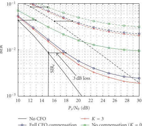
For the 2-user SDMA case, we consider ZF equalization to separate the signals of the different users. In [34] the diversity gain delivered by the ZF receiver has been shown to yieldμ=M−Q+ 1. For our examinations, we consider two cases: a receiver with M = 2 and M = 3 antennas, providing a diversity gain ofμ=1 andμ=2, respectively. Performance results are shown in Figure 4. The dashed curves refer toμ =1, while the solid curves refer toμ= 2. The curves representing full CFO compensation according to the proposed scheme exhibit a 3 dB performance loss at an SNR equal to the SIR from (58) compared to the curve of CFO-free transmission, which amounts to 16 dB forμ = 1 and 15 dB for μ = 2, respectively, for the given parameter setting. These losses are highlighted inFigure 4by the horizontal black lines, clearly verifying the bound derived in (58). As in the SISO case, we observe that we can achieve a slight performance improvement if we use the simplified CFO compensation process based on (29) withK=3. In case we do not compensate the ICI caused by the CFO, we achieve a severely degraded performance, which clearly exhibits a 3 dB performance loss at an SNR of 12 dB forμ=1 and 10 dB forμ=2, respectively, corresponding to the analytical bound (49).
InFigure 5we examine the behavior of the BER when the CFO compensation process based on (29) is applied for different values of the delimiterK. We focus on a constant SNRPs/N0=20 dB, which reflects the BER of the error floor
for μ = 1. For the selected values of N/L, the subcarrier correlation range Kc from (27) amounts to 3.2 and 1.6,
respectively. Interestingly, the corresponding curves exhibit their minimum atK=3 andK=2, respectively, which is the nearest integer toKc. Hence, selectingK=[Kc] indeed seems
to be a good choice. This result leads us to the conclusion that it definitely suffices to consider only the subcarrier signals in closest vicinity within the CFO compensation via (29).
To illustrate the performance degradation caused by the incomplete compensation of the CFO effects in the OFDM-SDMA system, we specify the effective SNR lossΔSNR based on the ratio of the interference power bound from (58) and the AWGN powerN0as done in [8], which yields (in dB)
ΔSNR =10 log10
1 + ηeNPs 2Lsin2(πω)N0
. (60)
The numerical evaluation of the effective SNR loss for various CFO sizes ω is depicted versus the SNR Ps/N0 in
Figure 6; the corresponding parameter setting is specified in its caption. In accordance with the observations drawn
10 12 14 16 18 20 22 24 26 28 30
Ps/N0(dB)
10−3
10−2
10−1
BER
SIR
e
3 dB loss
No CFO
Full CFO compensation
K=3
No compensation (K=0)
Figure4: BER performance of 2-user SDMA system distorted by
normalized CFOω= 0.1 with ZF receiver. Dashed line: diversity gainμ=1. Solid line:μ=2.
0 1 2 3 4 5 Full
DelimiterK
10−1.4
10−1.3
BER
N/L=16
N/L=8
Figure5: BER performance at SNR=20 dB versus delimiterK.μ=
1, Q=2,ω=0.1.
fromFigure 4, where evaluations where based on a CFO of sizeω= 0.1, the corresponding curve indicates here a 3 dB SNR loss at an SNRPs/N0=16 dB. For comparison, we also
added the SNR loss for the case of no ICI compensation (dashed curves), where we used the interference power bound from (49). Although we observe that the proposed CFO compensation is able to reduce the SIR loss significantly, it still increases steeply for increasing CFO sizeω. If the CFO amounts to 20% of the subcarrier spacing, the performance of the system is degraded by 3 dB already at an SNR level of about 10 dB.
0 2 4 6 8 10 12 14 16 18 20 22 24
Ps/N0(dB)
0 1 2 3 4 5 6
SNR
loss
(dB)
ω=0.025
ω=0.05
ω=0.1
ω=0.15
ω=0.2
Figure6: SNR loss after CFO compensation versus SNR for CFOs
of different sizeω. Solid line: ICI compensation. Dashed line: no compensation.μ=1, Q=2,N/L=16.
fine-frequency synchronization only, and hence it has to rely on a coarse synchronization, which has to be established in advance. In a practical system, such a coarse synchronization can be achieved if the terminals use their frequency estimates obtained during the preceding downlink phase for a proper frequency precompensation of their transmit signals. We denote this asfrequency advance, which has been the basic concept for our real-time system implementation that has been reported in [30]. It is worth noting that the analysis presented in this paper and in particular the derived bounds for the SIRs served as an important guideline in preparing the experiments that have been summarized in that reference, which have shown that a convenient system operation in a practical setup can be achieved.
Finally, note that if the CFOs are kept small, the signal degradation from ICI is limited, and thus common pilot-based channel estimation techniques can still be used to obtain channel estimates of sufficient quality. The more pilots available in one OFDM symbol can be used for that channel estimation, the better the ICI can be suppressed, as the ICI behaves similar to AWGN. Moreover, the CFOs ωq of the single users q ∈ {1,. . .,Q} can be obtained
from observing the phase drift of the estimated subcarrier channels λk over several successive OFDM symbols. With
(10), the ICI coefficientsu(κ) can then be determined, which can finally be applied in (29) for proper ICI compensation of the single users’ signals.
6. Conclusion
We have investigated OFDM-SDMA uplink transmission in the presence of multiple users’ CFOs. We modified the com-mon signal model suitably to enable a subcarrier-wise SDMA equalization followed by a user-specific CFO compensation,
yielding a simple equalization process ready to be applied in practice. However, as CFOs violate the periodic structure of the OFDM signals, some interference remains in the system after CFO compensation, which cannot be compensated as long as simple frequency domain processing is targeted. The SIR conditions in OFDM-SDMA systems have been analyzed if CFOs are compensated according to the proposed scheme as well as if they are not. We derived suitable upper bounds for the SIRs depending on the system parameters, which have been verified by numerical simulations. To enable a convenient operation of the proposed scheme, we conclude from the results that the users’ CFOs should not exceed values that are much larger than a few percent of the OFDM subcarrier spacing, which classifies this scheme as a tech-nique for fine frequency synchronization. Correspondingly, coarse-frequency synchronization has to be ensured, which can easily be established if the CFO estimates from the downlink are used in the uplink for a proper predistortion of each user’s transmit signal, as suggested also in [10] and practically realized in [30]. Together with this concept, the proposed scheme can be regarded as a convenient solution to synchronize the OFDM-SDMA uplink. Note that this concept based on coarse synchronization also enables to estimate user channels based on common pilot-based channel estimation techniques. Suitable estimates of the users’ CFOs can then be obtained from the phase drift of the estimated channels observed over several consecutive OFDM symbols.
Appendix
A. Correlation between Self-Interference and
Useful Signal
To determine the correlation between the self-interference and the useful signal at any subcarrierk, we determine the covariance between the self-interference coefficient (i.e., the kth diagonal element of matrix V) and the channel coef-ficient λk. As indicated earlier, the interference conditions
evoked by matrixVare independent of the actual subcarrier positionk, and hence it suffices to determine the covariance at a single subcarrier position; specifically we choosek =1. The channel coefficient is given asλ1 =
L
l=0hl. Denote the
first diagonal element ofVasv11. Considering the structure
of matrixVbased on the submatrixVu(seeSection 3.2),v11
can be calculated as
v11=
1 N
L−1
m=0
L
l=m+1
γ−l+mhl. (A.1)
As both coefficientsλ1andu11have an expectation value of
zero, the covariance is defined as cov = E{λ∗1v11}. With
the uniform PDP, we yield for the covariance of the two coefficients
cov= γ−1 N(L+ 1)
L
m=1
L−m
l=0
The second sum term on the right hand side represents a geometric series, so that similarly to (10) the si-function can be used to obtain an approximation, which is given as
L−m
l=0
exp−jϕl=exp
−jπωL−m N
≈1
si
πωL−m+ 1 N
≈1
·(L−m).
(A.3)
As usually L N holds, the exponential function as well as the si-function generate values that are very close to one for any m ∈ {1,. . . L}. Hence, both terms can be upper bounded with constant value one. Herewith the covariance can be upper bounded by
cov <γ−1L
2N . (A.4)
Assuming the signalsλ1,v11to be Gaussian, the amount
of power Pc devoted to the self-interference can with [35,
Theorem 10.1] be determined by
Pc= |cov|2·Ps< L
2
N2sin
2(πω)·P
s. (A.5)
With this result, we can assess the ratio of the self-interference power to the total self-interference powerPi(ω) given
in (25), yielding
Pc
Pi(ω)≈
L
2N. (A.6)
ForLN, we conclude that the amount of self-interference is vanishingly small; hence there is no need to consider the self-interference separately to account for its special properties.
References
[1] P. Vandenameele, L. van der Perre, M. G. E. Engels, B. Gyselinckx, and H. J. De Man, “A combined OFDM/SDMA approach,”IEEE Journal on Selected Areas in Communications, vol. 18, no. 11, pp. 2312–2321, 2000.
[2] X. Cai and G. B. Giannakis, “Bounding performance and sup-pressing intercarrier interference in wireless mobile OFDM,”
IEEE Transactions on Communications, vol. 51, no. 12, pp. 2047–2056, 2003.
[3] P. Jung and G. Wunder, “On time-variant distortions in multicarrier tansmission with application to frequency offsets and phase noise,”IEEE Transactions on Communications, vol. 53, no. 9, pp. 1561–1570, 2005.
[4] T. Keller, L. Piazzo, P. Mandarini, and L. Hanzo, “Orthogonal frequency division multiplex synchronization techniques for frequency-selective fading channels,”IEEE Journal on Selected Areas in Communications, vol. 19, no. 6, pp. 999–1008, 2001. [5] B. Ai, Z.-X. Yang, C.-Y. Pan, J.-H. Ge, Y. Wang, and Z. Lu, “On
the synchronization techniques for wireless OFDM systems,”
IEEE Transactions on Broadcasting, vol. 52, no. 2, pp. 236–244, 2006.
[6] L. H¨aring and A. Czylwik, “Synchronization in MIMO-OFDM systems,”Advances in Radio Sciences, vol. 2, pp. 147–153, 2004.
[7] A. M. Tonello, N. Laurenti, and S. Pupolin, “Analysis of the uplink of an asynchronous multi-user DMT OFDMA system impaired by time offsets, frequency offsets, and multi-path fading,” inProceeding of the 52nd IEEE Vehicular Technology Conference (VTC ’00), vol. 3, pp. 1094–1099, Boston, Mass, USA, September 2000.
[8] M. S. El-Tanany, Y. Wu, and L. Hazy, “OFDM uplink for interactive broadband wireless: analysis and simulation in the presence of carrier, clock and timing errors,”IEEE Transactions on Broadcasting, vol. 47, no. 1, pp. 3–19, 2001.
[9] L. Kuang, J. Lu, Z. Ni, and J. Zheng, “Nonpilot-aided carrier frequency tracking for uplink OFDMA systems,” in Proceed-ings of IEEE International Conference on Communications (ICC ’04), vol. 6, pp. 3193–3196, Paris, France, June 2004.
[10] M. Morelli, C.-C. Kuo, and M.-O. Pun, “Synchronization techniques for orthogonal frequency division multiple access (OFDMA): a tutorial review,”Proceedings of the IEEE, vol. 95, no. 7, pp. 1394–1427, 2007.
[11] J.-J. van de Beek, P. O. B¨orjesson, M.-L. Boucheret, et al., “A time and frequency synchronization scheme for multiuser OFDM,”IEEE Journal on Selected Areas in Communications, vol. 17, no. 11, pp. 1900–1914, 1999.
[12] H. B¨olcskei, “Blind high-resolution uplink synchronization of OFDM-based multiple access schemes,” inProceedings of the 2nd IEEE Workshop on Signal Processing Advances in Wireless Communications (SPAWC ’99), pp. 166–169, Annapolis, Md, USA, May 1999.
[13] S. Barbarossa, M. Pompili, and G. B. Giannakis, “Channel-independent synchronization of orthogonal frequency divi-sion multiple access systems,”IEEE Journal on Selected Areas in Communications, vol. 20, no. 2, pp. 474–486, 2002. [14] Y. Yao and G. B. Giannakis, “Blind carrier frequency offset
estimation in SISO, MIMO, and multiuser OFDM systems,”
IEEE Transactions on Communications, vol. 53, no. 1, pp. 173– 183, 2005.
[15] Z. Cao, U. Tureli, and Y.-D. Yao, “User separation and frequency-time synchronization for the uplink of interleaved OFDMA,” inProceedings of the 36th Asilomar Conference on Signals, Systems and Computers, vol. 2, pp. 1842–1846, Pacific Grove, Calif, USA, November 2002.
[16] M. Morelli, “Timing and frequency synchronization for the uplink of an OFDMA system,” IEEE Transactions on Communications, vol. 52, no. 2, pp. 296–306, 2004.
[17] M.-O. Pun, M. Morelli, and C.-C. J. Kuo, “Maximum-likelihood synchronization and channel estimation for OFDMA uplink transmissions,”IEEE Transactions on Commu-nications, vol. 54, no. 4, pp. 726–736, 2006.
[18] Z. Cao, U. Tureli, Y.-D. Yao, and P. Honan, “Frequency syn-chronization for generalized OFDMA uplink,” inProceedings of IEEE Global Telecommunications Conference (GLOBECOM ’04), vol. 2, pp. 1071–1075, Dallas, Tex, USA, November 2004. [19] C. Ibars and Y. Bar-Ness, “Inter-carrier interference cancel-lation for OFDM systems with macrodiversity and multiple frequency offsets,”Wireless Personal Communications, vol. 26, no. 4, pp. 285–304, 2003.
[20] R. Fantacci, D. Marabissi, and S. Papini, “Multiuser interfer-ence cancellation receivers for OFDMA uplink communica-tions with carrier frequency offset,” in Proceedings of IEEE Global Telecommunications Conference (GLOBECOM ’04), vol. 5, pp. 2808–2812, Dallas, Tex, USA, November 2004. [21] D. Huang and K. B. Letaief, “An interference-cancellation
[22] W. G. Jeon, K. H. Chang, and Y. S. Cho, “An equalization technique for orthogonal frequency-division multiplexing sys-tems in time-variant multipath channels,”IEEE Transactions on Communications, vol. 47, no. 1, pp. 27–32, 1999.
[23] C.-Y. Hsu and W.-R. Wu, “Low-complexity CFO compen-sation for uplink OFDMA systems,” in Proceedings of the 17th IEEE International Symposium on Personal, Indoor and Mobile Radio Communications (PIMRC ’06), pp. 1–5, Helsinki, Finland, September 2006.
[24] J. Choi, C. Lee, H. W. Jung, and Y. H. Lee, “Carrier frequency offset compensation for uplink of OFDM-FDMA systems,”
IEEE Communications Letters, vol. 4, no. 12, pp. 414–416, 2000.
[25] M. Schellmann and S. Stanczak, “Multi-user MIMO channel estimation in the presence of carrier frequency offsets,” in
Proceedings of the 39th Asilomar Conference on Signals, Systems and Computers, pp. 462–466, Pacific Grove, Calif, USA, October 2005.
[26] S. Ahmed, S. Lambotharan, A. Jakobsson, and J. Chambers, “MIMO frequency-selective channels with multiple frequency offsets: estimation and detection techniques,”IEE Proceedings: Communications, vol. 152, no. 4, pp. 489–494, 2005.
[27] L. H¨aring, S. Bieder, and A. Czylwik, “Closed-form estimators of carrier frequency offsets and channels in the uplink of mul-tiuser OFDM systems,” in Proceedings of IEEE International Conference on Acoustics, Speech and Signal Processing (ICASSP ’06), vol. 4, pp. 661–664, Toulouse, France, May 2006. [28] K.-H. Wu, W.-H. Fang, and J.-T. Chen, “Joint DOA-frequency
offset estimation and data detection in uplink MIMO-OFDM networks with SDMA techniques,” inProceedings of the 63rd IEEE Vehicular Technology Conference (VTC ’06), vol. 6, pp. 2977–2981, Melbourne, Canada, May 2006.
[29] S. Sezginer and P. Bianchi, “Asymptotically efficient reduced complexity frequency offset and channel estimators for uplink MIMO-OFDMA systems,”IEEE Transactions on Signal Pro-cessing, vol. 56, no. 3, pp. 964–979, 2008.
[30] V. Jungnickel, M. Schellmann, A. Forck, et al., “Demonstration of virtual MIMO in the uplink,” inIET Smart Antennas and Cooperative Communications Seminar, London, UK, October 2007.
[31] M. Schellmann and V. Jungnickel, “Effects of multiple users’ CFOs in OFDM-SDMA up-link: an interference model,” in
Proceedings of IEEE International Conference on Communica-tions (ICC ’06), vol. 10, pp. 4642–4647, Istanbul, Turkey, June 2006.
[32] P. H. Moose, “Technique for orthogonal frequency division multiplexing frequency offset correction,”IEEE Transactions on Communications, vol. 42, no. 10, pp. 2908–2914, 1994. [33] T. M. Schmidl and D. C. Cox, “Robust frequency and
timing synchronization for OFDM,” IEEE Transactions on Communications, vol. 45, no. 12, pp. 1613–1621, 1997. [34] J. H. Winters, J. Salz, and R. D. Gitlin, “The impact of antenna
diversity on the capacity of wireless communication systems,”
IEEE Transactions on Communications, vol. 42, no. 234, part 3, pp. 1740–1751, 1994.