R E S E A R C H
Open Access
Interference alignment for a multi-user SISO
interference channel
Yasser Fadlallah
*, Karine Amis, Abdeldjalil Aïssa-El-Bey and Ramesh Pyndiah
Abstract
Our work addresses the single-input single-output interference channel. The goal is to show that although
interference alignment is suboptimal in the finite power region, it is able to achieve a significant overall throughput. We investigate the interference alignment scheme proposed by Choi et al. (IEEE Commun. Lett. 13(11): 847-849, 2009), which achieves a higher multiplexing gain at any given signal dimension than the scheme proposed by Cadambe and Jafar (IEEE Trans. Inform. Theory 54(8), 2008). Then, we try to modify the IA design in order to achieve enhanced sum-rate performance in the practical signal-to-noise ratio (SNR) region. Firstly, we introduce a way to optimize the precoding subspaces at all transmitters, exploiting the fact that channel matrices in the interference model of a single-input single-output channel are diagonal. Secondly, we propose to optimize jointly the set of precoder bases within their associated precoding subspaces. To this end, we combine each precoder with a new combination precoder, and this latter seeks the optimal basis that maximizes the network sum rate. We also introduce an improved closed-form interference alignment scheme that performs close to the other proposed schemes.
Keywords: Interference channel; Single input single output; Optimization problem; Precoding; Interference alignment
1 Introduction
In most existing wireless multi-user communication sys-tems, interference is avoided either by coordinating the users to orthogonalize the channel access or by treat-ing interference from other transmitters as noise. How-ever, until recently, the capacity region of the interference channel (IC) remained unknown, except for some special cases such as strong and very strong interference [1,2]. In [3], Maddah-ali et al. have proposed a new approach in order to show that the N-antennas MIMO X chan-nels can offer as much as 43N degrees of freedom (DoF). This new approach of interference management has been named IA.
The key idea of IA is to jointly design all transmit-ted signals such that interfering signals at each receiver overlap and remain distinct from the desired signal. This approach has been exploited by Cadambe and Jafar in [4]. The authors have shown that the maximum achiev-able DoF in theK-user time-varying input single-output (SISO) IC, in thendimensional Euclidean space,
*Correspondence: [email protected]
Institut Télécom; Télécom Bretagne; UMR CNRS 6285 Lab-STICC, Technopôle Brest Iroise CS 83818, Brest 29238, France
is K2 and is achieved, thanks to an IA scheme. Later on, Motahari et al. have addressed the achievable DoF of a quasi-static IC. They have extended the idea of IA from space/time/frequency dimensions to the signal level dimensions and have shown that based on the field of Diophantine approximation in number theory [5], the interference can be aligned in the rational spaces, achiev-ing a maximum DoF ofK2.
The first IA scheme for SISO transmissions has been proposed in [4] for the time/frequency-varying channel. This scheme has been designed to achieve the asymp-totic capacity in the IC, i.e., when both the signal-to-noise (SNR) and the signal dimensions tend to infinity. In contrast, Choi et al. have introduced another IA design that aims to achieve a higher multiplexing gain at any given signal dimension [6]. In this paper, we adopt an IA scheme for SISO transmission, and we try to modify the design in order to achieve higher sum-rate performance in the practical SNR region. Most ref-erences, among which [7-9], deal with IA schemes for MIMO interference channels. However, all mobile com-munication standards still include a SISO transmission
mode as for instance the LTE downlink transmission mode 1. This is the reason why in this paper, we try to define efficient IA schemes for SISO interference channels.
In our contributions, we firstly introduce a way to opti-mize the precoding subspaces at all transmitters, exploit-ing the fact that channel matrices in the IA model are diagonal. Two solutions are derived; the first is achieved iteratively using projected gradient descent method, the second is a closed-form solution that avoids the numerical computation, thus, resulting in a very low computational complexity. Secondly, we propose to optimize the pre-coding vectors at each transmitter within its prepre-coding subspace. To this end, we combine each IA precoder with a new combination precoder. The combination precoder seeks the optimal basis that maximizes the network sum-rate assuming an individual transmit power constraint. However, a closed-form solution does not seem trivial. Therefore, we apply an iterative process based on the simple gradient descent method, which converges to a local maximum due to the non-concavity of the objective function.
This paper is organized as follows. Section 2 describes the system model. Then, Section 3 presents the IA design in SISO IC. In Section 4, we propose to optimize the network sum rate through a diagonal matrix W. The precoding vector optimization within the IA subspaces is presented in Section 5. In Section 6, we present the convergence rate of the proposed iterative algorithms. Section 7 evaluates the sum-rate performance of the pro-posed optimization. Finally, Section 8 concludes the paper. Notations: boldface upper case letters and boldface lower case letters denote matrices and vectors, respec-tively. For the transpose, transpose conjugate, and conju-gate matrices, we use(.)T,(.)H, and(.)∗, respectively.Ipis thep×pidentity matrix, and1pis the all-one vector of lengthp.
2 System model
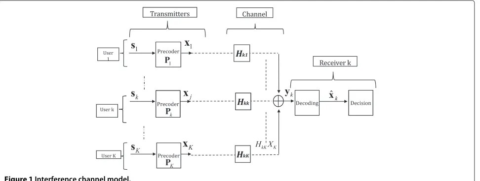
Let us assume a K-user SISO IC with K transmitter-receiver pairs. A wireless channel links each transmitter-receiver to each transmitter, but a given transmitter intends to have its signal decoded by a single dedicated receiver only. Let us denote bysjthe lengthdjsymbol vector to be transmit-ted by thejth user. As shown in Figure 1,sjis precoded by applying anN×djprecoding matrix yielding the lengthN vectorxj. We assume a frequency-selective channel, and the inter-symbol interference is perfectly managed using an orthogonal frequency division multiplexing (OFDM) transmission scheme. The number of subcarriers is equal toN, and all components ofxj are simultaneously trans-mitted on a one-component-per-subcarrier basis. The received signal at thekth receiver can be modeled as
yk=
K
j=1
HkjVjxj+zk, ∀k∈K, (1)
whereK = {1,· · ·,K}is the set of all users,Hkj ∈CN×N is the diagonal channel matrix between thejth transmitter and thekth receiver,Vj ∈CN×dj is the precoding matrix of thejth transmitter. Thejth transmitted informationxj is defined as adj×1 vector belonging to a Gaussian con-tinuous constellation.zkis theN×1 circularly symmetric complex Gaussian noise vector at the receiverk, with inde-pendent and identically distributed (i.i.d.) components, i.e. zk ∼ Nc(0,σ2IN). We also consider the following hypotheses in this paper:
1. Users do not cooperate.
2. Non-precoded user symbols are Gaussian
continuously distributed and mutually independent. 3. The set of channel matricesHkjis entirely and
perfectly known at all transmitters and all receivers. 4. All diagonal components ofHkj∀k,j∈Kare i.i.d.
and continuously distributed, with absolute values upper-bounded with a finite value.
The maximum achievable DoF in theK-user SISO IC is equal to [4,5]
lim snr→∞
C(snr)
log2(snr) = K
2 , (2)
whereC(snr)represents the channel capacity.
3 IA design in a SISO interference channel
3.1 Precoding design
The essence of the IA scheme is to design the transmit beamforming matrices in a way that the interference-free stream number at each receiver is maximized. The IA design conditions have been defined as follows:
rank(UkHkkVk)=dk,
UkHkjVj=0,∀j=k,
(3)
where Uk is the decoding matrix at thekth receiver. In other words, the desired signal belongs to the subspace generated by the vectors of Gk = UkHkkVk, while the interference is completely eliminated. The feasibility of the linear system in (3) is conditioned to the following pro-prieties: (i) the linear system has to be proper, i.e., the number of variables is more than or equal to the number of equations and (ii) the linear system has to be generic [10]. In some particular cases, the genericity is satisfied by providing a channel matrix with random and independent coefficients.
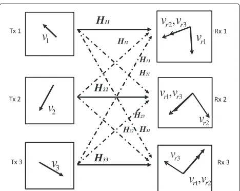
Figure 2 illustrates the IA principle in the case of three users sharing the same resources to communicate. Each transmitter has one symbol to transmit to its ded-icated receiver. All channel coefficients are supposed to be known at all transmittersa. In order to achieve the IA linear precoding design, each transmitterktransmits its symbol in the direction of a two-dimensional vectorvk, and the precoding vectors at all transmitters are designed in such a way that at all receivers the vectors carrying the two interfering symbols are aligned and linearly indepen-dent of the vector that carries the desired symbol. Then, the interference is eliminated by a simple projection on the interference null space.
One precoding design that provides IA at all receiver nodes and fulfills the conditions in (3) in the SISO inter-ference channel is proposed by Choi et al. as [6]
Figure 2Three-user SISO interference channel with IA scheme.
where m∗ is any non-negative integer which defines the number of transmitted symbols and the length of the precoding vectors, and Tkl is an N × N diagonal matrix. In the IA design described previously, the achiev-able DoF per user can be obtained using the following combinations:
d1=
m∗+M+1
M
and d3=
m∗+M
M
,
whereMis a parameter depending on the user number,
M=(K−1)(K−2)−1,diis the DoF of theith user, i.e., the number of transmitted symbols, andNthe number of symbols in each IA vector is defined asN = d1+d2. In the particular scheme previously, the IA conditions can be satisfied by providingdi = d3 ,d1 > d3, i ∈ K\{1, 3}. For example, in a three-user SISO multi-user IC, we have
d1= n+1,d2= d3= n,N = 2n+1, andncan be any non-negative integer.
3.2 Linear decoding design
In the aforementioned transmission model, the received signal given in (1) can be rewritten as
V1= ⎧ ⎨ ⎩
k,l∈K\1,k=l,(k,l)=(2,3)
(T23)−1Tkl
nkl
|
k,l∈K\1,k=l,(k,l)=(2,3)
nkl≤m∗+1
⎫ ⎬ ⎭,
V3= ⎧ ⎨ ⎩(T23)−1
k,l∈K\1,k=l,(k,l)=(2,3)
(T23)−1Tkl
nkl |
k,l∈K\1,k=l,(k,l)=(2,3)
nkl ≤m∗
⎫ ⎬ ⎭ ,
Vj=H−1j1H13V3,
Tkl=(Hk1)−1Hkl(H1l)−1H13.
yk= H ¯kksk matrix spanning all interference subspaces, i.e.,H¯kj forj∈
{1,· · ·,K}, j = k are all spanned byH¯kI. Before going
further into the description, we introduce the following lemma:
Using Lemma 1 at the receiverk, the interference sub-space from thejth transmitter can be expressed in terms ofH¯kI as
Substituting (6) into (5) yields
yk =H¯kksk+H¯ of the desired and the interference subspaces, and ˜sk is the N × 1 vector consisting of the dk desired streams and theN−dkinterference streams. Equation 7 gives the mathematical formulation of a linear determined decod-ing problem, where anN length source data vectors˜k is mixed by a constant mixing matrixBk to produce a vec-torykofNobservations. Such a decoding problem can be resolved using classical criteria such as zero-forcing (ZF), minimum mean square error (MMSE), and maximum likelihood (ML).
4 IA precoding subspaces optimization
In this section, we aim to optimize the IA precoding sub-spaces in the scheme described above. From (3), it can be noted that the modified precoding matrices defined as
Vk =W VIAk ∀k∈K, (8)
whereVIAk is the original matrix derived with respect to the IA conditions and W is any diagonal matrix, which
satisfy the IA conditions. That is, the projection of all pre-coding matrices of the IA scheme on a common diagonal matrixW keeps the IA conditions respected.
The precoding subspaces can be optimized by judi-ciously selecting the components ofW in (8). This diago-nal matrixW determines the interference and the desired subspaces design, while maintaining the IA conditions at the receivers. We assume both MMSE- and ZF-based detection schemes, widely used due to the simplicity of their implementation, and we derive two different opti-mized designs that maximize the network sum rate in both cases.
4.1 MMSE-based decoder - iterative solution
Assuming an MMSE decoder, the mutual information between the kth transmitter and its intended receiverk
can be expressed as [11]
Rk(w)=log2
wherepis the user average transmit power over the aver-age noise power assumed equal at all receivers. Using the Sylvester’s determinant theorem [12], the fact that all channel matrices are diagonal, and the definition ofBkand
Akas
(9) can be reformulated in the following compact form as
Rk(w)˜ =log2 nal is defined as the vectorw˜ with positive components (w˜i ∀i). One can notice from (10) that matricesAk and
Bkare written as the sum of semi-definite positive matri-ces and hence are positive semi-definite. Consequently, the Cholesky decompositionbcan be applied [13], and the matricesAkandBkcan be rewritten as
Ak=LHAkLAkwithL
Substituting (12) into (11) yields thekth user rate
Our goal is to seekw˜ that maximizes the total mutual information (i.e., network sum rate) in the IC under the constant total transmit power linear constraint. The max-imization problem is then defined as
arg max
subject to the total transmit power constraint
K
It is not obvious whether a closed-form solution can be obtained or not; therefore, one can search for the solution iteratively. However, the convergence towards the global maximum is not guaranteed unless the objective func-tion is concave. The proof of the concavity with respect to the variable vectorw˜, requires the objective function to be twice differentiable and its Hessian matrix to be negative semi-definite [14]. Indeed, a similar problem has been treated in [15] for the three-user IA scheme. The authors have demonstrated that a function having the form of (14) is concave if Ak and Bk are defined as in (12) (see Appendix 1 in [15]). In order to find the solution that achieves the optimum, we propose to use the pro-jected gradient method with an optimized variable step size (details are given in Appendix 2). Other algorithms can also be used such as simple gradient descent method using Lagrange multipliers.
Remark 1.In [15], the diagonal matrixWhas been opti-mized under an MMSE receiver assumption. However, the study has been restricted to the three-user SISO inter-ference channel case. Also, there is no description of the iterative algorithm used for achieving the solution. In this section, we have provided a general design for theK-user SISO interference channel case. We have also described an iterative method (see Appendix 2) to converge towards the solution.
4.2 ZF-based decoder - closed-form solution
In the previous subsection, we have proposed to optimize the precoding subspaces using iterative processing when an MMSE is applied at the receiver. In this section, we apply a ZF criterion at the receiver. Then, we propose a closed-form solution forwthat is asymptotically optimal. This solution is obtained from the network sum-rate max-imization problem approximation for very high SNR and under the hypothesis of a ZF applied at all receivers. It also avoids the need for a numerical solver that requires a matrix inversion at each iteration and increases the processing time and computational cost.
Assuming a ZF criterion at all receiver nodes and an IA design at all transmitters, the mutual information between thekth transmitter and its intended receiverkis expressed as
Rk =log2|IN +pUkHkkW VkVHkWHHHkkUHk| (15)
whereUk is the interference canceler at thekth receiver. Assuming well-conditioned channel matrices and using Sylvester’s determinant theorem [12], thekth user rate can be approximated for high SNR values by
Rk ≈
SNR>>1log2pHkkW VkV H
kWHHHkkUHkUk. (16)
Now, we intend to maximize the sum-rate approxima-tion kRk with respect to w under the total transmit power constraint. Using the following equivalence:
arg max the optimization problem in (17) can also be reduced to
arg max
We notice that the problem in (18) is independent from the channel matrices, and the objective function is a sim-ple determinant of a diagonal matrix, hence, a concave function. Introducing the Lagrange multiplierλ, the con-vex dual of this problem is formulated as follows [14]:
arg max
where the Lagrangian function is defined as
L(w˜,λ)=W˜−λtr objective function is concave, the Karush Kuhn-Tucker (KKT) conditions are sufficient to determine the global optimum. The KKT conditions of the problem in (19) are given by
∇w˜L(w˜,λ)|w˜=w˜∗=0 ,λ >0 ,
N
i=1ciw˜i=K N
(21)
The solution of the linear problem in (21) is obtained as
˜
w∗i = K ci
Hence, the components ofware obtained asw∗i = w˜∗i
for alli. It is worth noting that beside maximizing the sum-rate, the problem of maximizing the individual rate using the approximation in (16) has the same solution obtained in (22).
A major advantage of the proposed solution is the fact that it has an analytic simple expression making its implementation complexity very low. Indeed, the other algorithms proposed for sum-rate maximization and interference power minimization in SISO and MIMOc transmissions achieve the optimum using singular value decomposition (SVD) [11] and/or an iterative algorithm that requires hundreds to thousands iterations to converge [7-9,16].
4.3 Complexity and sum-rate performance
The computational complexity is a major bottleneck of practical implementation that is considered in system designs. In the following, we discuss the complexity of the precoding schemes proposed above.
The first optimized design that maximizes the sum-rate assuming an MMSE detector is obtained using the pro-jected gradient descent method. This iterative method requires at each iteration the computational cost of the first-order derivative of the objective function. Looking at the expression given in (34), one can notice that the derivative is calculated using matrix multiplications and matrix inversions with dimensionsN×N. Therefore, the computational complexity at each iteration can be consid-ered of orderO N3. On the other hand, the design based on a closed-form solution requires the computation of a Frobenius norm andNreal division. Thus, the complexity order isO(N).
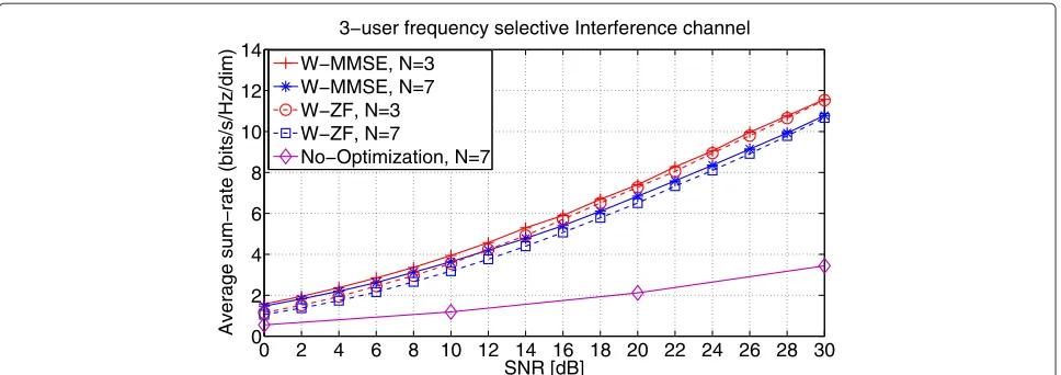
Figure 3 illustrates the average sum-rate per dimension performance of the non-optimized design proposed by Choi et al. in [6] and the optimized designs W-MMSE and W-ZF, which represent the designs based on the solutions to the problems given in (14) and (18), where we opti-mize the precoding subspaces of the IA scheme assuming an MMSE and a ZF, respectively. The optimizations are applied to the IA design proposed by Choi et al. It can be observed that forN = 3 andN = 7, the W-MMSE design outperforms the W-ZF design with the closed-form solution in the low SNR region. However, when the SNR becomes very high, the sum-rate performance for both designs get very close. This is due to the validity of the approximation in (16) for high SNR. On the other hand, the resulting gain of the optimized designs over the nonoptimized one is significant, e.g., at 20dB the gain is between 4 and 5 bits/s/Hz/dim.
It is important to note that the proposed designs result from the optimization of the original designs proposed in [6] and not the optimal IA design that maximizes the sum-rate. It explains why, when we compare the designs for
different dimensionsN, a higher sum-rate is obtained for
N=3 compared to the design forN=7. Furthermore, in order to have a fair comparison between the casesN =3 andN =7, the average sum rate performance is normal-ized by the dimensionN, which means that the sum rate is divided by the number of symbols in one symbol vector as shown in (14).
5 Precoding vectors design within IA subspaces
The previous section has addressed the optimization of the IA precoding subspaces at once using a diagonal matrixW. However, there was no claim for the optimal-ity of the precoding vectors within IA subspaces. In this section, we propose to maintain the IA subspaces design at the transmitters, and we aim to optimize the precod-ing vectors within each subspace. We consider both cases: MMSE and ZF criterion at the receiver, and we attempt to maximize the network sum-rate in each case.
The precoding matrices defined in (4) are of sizeN×dk
withN > dk, ∀k. Thus, introducing a new combination matrixCk ∈Cdk×dkat each transmitter node as follows
Pk =VkCk, ∀k∈K, (23)
will modify the basis ofVkwithin its own subspace with-out modifying the subspace itself. These variables can later be defined taking into account different criteria such as MSE, BER, sum-rate, and average transmit power. Next, we show how to optimize the additional combination matrices so as to maximize the network sum-rate.
5.1 MMSE-based decoder
Assuming an MMSE at all receivers, the mutual infor-mation between the kth transmitter and its dedicated receiverkcan be written as a function of the combination matricesCk∀kas follows
0 2 4 6 8 10 12 14 16 18 20 22 24 26 28 30 0
2 4 6 8 10 12 14
SNR [dB]
Average sum−rate (bits/s/Hz/dim)
3−user frequency selective Interference channel
W−MMSE, N=3 W−MMSE, N=7 W−ZF, N=3 W−ZF, N=7
No−Optimization, N=7
Figure 3Average sum rate per dimension of the two proposed designs for subspace improvement whenN=3 andN=7.
attempt to get close to the solution iteratively. We use an iterative algorithm that optimizes the cost function with respect to one variable while the others remain fixed. In our reasoning, each variable is considered as one of the precoding matrices. This technique results in a nonconvex optimization due to the dependence between the precod-ing matrices. At each iteration, the optimization is based on the gradient descent widely used in MIMO multi-user channels. The iterative algorithm for the sum-rate maximization is detailed in Algorithm 1.
Algorithm 1 IA precoding vectors optimization 1: Initialize randomly all precoding matricesC1,· · ·CK. 2: Start loop withl=1
3: fork=1toKdo
4: Calculate the gradient,∇Ckf
Cl1,· · ·,ClK
.
5: UpdateC(kl+1)=Clk+λ.∇Ck f
Cl1,· · ·,ClK
.
6: if trace
VkC(kl+1)C
(l+1)H
k VHk
>NupdateC(kl+1)=
N dkC
(l+1) k
traceVkC(kl+1)C (l+1)H k VHk
.
7: end for
8: If f
C(1l+1),· · ·,CK(l+1)−fCl1,· · ·,ClK > , set
l = l+1 and go back to step 3), otherwise stop the processing.
In this algorithm the gradient is defined in (32) in Appendix 1, f describes the objective function given in (25), and the precoding matrices are supposed to be of unit Frobenius norm. The step size λ is updated using the backtracking search, which is an effective and quite simple method [14]. Despite the non-convexity of the multi-variable objective function, as long as the variable is
steered in the gradient direction, the algorithm converges to a local maximum. In our simulations, the convergence of this iterative algorithm is supposed to be achieved either when
k
∇C(l)
k
R< (26)
or when a maximum number of iterations is reached, and
is defined as a tolerance value. In our simulations, we assume=10−2.
5.2 ZF-based decoder
Given the kth user rate, the ZF-based detector uses a matrixUk to cancel the interference, yielding an equiv-alentdk×dk MIMO transmission model. Many options exist to find the best family of combination matrices{Cj} in order to maximize the sum-rate. The channel model after interference suppression at receiverkis obtained as
yk=UkHkkVkCkxk+Ukzk,
=H˜kCkxk+Ukzk,
(27)
5.3 Complexity and sum-rate performance
The algorithm that optimizes the solution iteratively in Subsection 5.1 is based on the gradient descent method. At each iteration, the iterative algorithm requires the gra-dient of the objective function that needs itself inversion ofN×Nfull rank matrices. Thus, the total computational complexity depends mainly on the number of iterations and on the precoding matrices dimensions. The complex-ity cost is of orderO(nbiN3)wherenbiis the number of iterations.
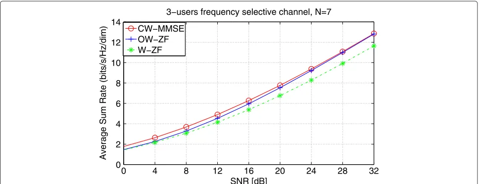
Figure 4 illustrates the sum-rate per dimension of the proposed design that uses Algorithm 1 and the design OW-ZF that orthonormalizes the precoding vectors. For the subspace optimization of OW-ZF, we use the closed form solution derived in Subsection 4.2. One can observe a sum-rate performance loss in the case of OW-ZF com-pared to the CW-MMSE for low SNR values, whereas when the SNR increases, both sum rates become very close. However, the OW-ZF requires less operations, the complexity cost is of orderO(Nd2k) at each transmitter, and no joint processing is required for the optimization design.
Remark 2.The proposed optimization of IA precoding
subspaces cannot directly be extended to MIMO interfer-ence channels, as the channel matrices are no longer diag-onal in the MIMO system model. However, the proposed optimization of the precoding vectors within each IA sub-space can be used for MIMO optimization design since the IA conditions at all receiver are always maintained.
6 Convergence rate of the iterative solutions
In Subsections 4.1 and 5.1, we have proposed two iter-ative solutions, one aims to optimize the IA subspaces
and the other optimizes the precoding vectors within each IA subspace without modifying the subspace itself.
The first iterative solution to the problem in (14) for the IA subspaces optimization is reached using the projected gradient method. We have mentioned that the objec-tive function is concave, thus, the convergence towards the global optimum is guaranteed. On the other hand, the iterative solution proposed for the IA precoding vec-tor optimization is reached using an algorithm based on the gradient descent method for a multi-variable objec-tive function. Thereby, the objecobjec-tive function changes at every iteration yielding a nonconvex optimization problem. However, as long as the iterative method is based on the gradient descent and the variable fol-lows the direction of the gradient using an optimized step size, a convergence towards a local optimum is guaranteed.
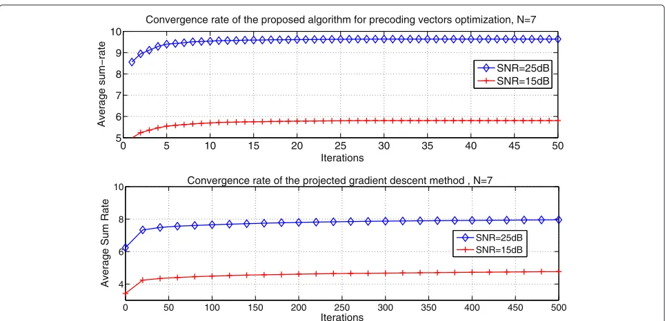
The convergence rates of the discussed iterative solu-tions above are shown in Figure 5. For the projected gradient descent method, the convergence towards either the optimal solution or a neighboring optimal solution requires hundreds of iterations. This slow convergence rate diverts the attention to the closed-form solution obtained in Subsection 4.2. Now, looking at the design for precoding vector optimization within their subspace, the convergence rate seems fast. For example, almost 10 to 15 iterations are required to achieve a near-optimal value at 15 and 25 dB when N = 7. This fast convergence implies that for small dimensions and for precoding vector optimization as discussed in Subsection 5.2, the compu-tational complexity is not that far from other proposed designs.
0 4 8 12 16 20 24 28 32
0 2 4 6 8 10 12 14
SNR [dB]
Average Sum Rate (bits/s/Hz/dim)
3−users frequency selective channel, N=7
CW−MMSE OW−ZF W−ZF
0 50 100 150 200 250 300 350 400 450 500 4
6 8 10
Iterations
Average Sum Rate
Convergence rate of the projected gradient descent method , N=7
SNR=25dB SNR=15dB
0 5 10 15 20 25 30 35 40 45 50
5 6 7 8 9 10
Iterations
Average sum−rate
Convergence rate of the proposed algorithm for precoding vectors optimization, N=7
SNR=25dB SNR=15dB
Figure 5Convergence of the iterative algorithm in Section 5.1 and the projected gradient method in Subsection 4.1.
7 Comparison of the proposed optimized designs to the state of art schemes
In this section, we compare the proposed designs to the distributed designs proposed in [7,8] in terms of sum-rate per dimension. We consider a three-user frequency-selective SISO IC, with the model proposed in Section 2. The total independent stream number from all users is equal toT = 3n+1, and the precoding vectors length is N = 2n + 1 for all users, and n can be any non-negative number. The transmit constellation is Gaussian continuously distributed, and the channel coefficients are circularly symmetric complex Gaussian distributed with zero mean and unit variance. The following abbreviations are used for the compared designs:
• OW-ZF : the proposed IA design with the
closed-form solution derived in Subsection 4.2 that uses orthogonal precoding vectors
• CW-MMSE: the IA design with the two iterative proposed optimization in Subsections 4.1 and 5.1 • IA-Iter: the IA design obtained with the distributed
algorithm proposed in [8]
• Max-SINR: the beamforming design proposed in [7] that maximizes the signal-to-interference-and-noise ratio (SINR) of all streams
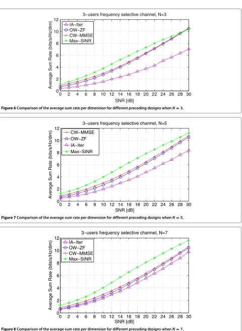
Figures 6, 7 and 8 illustrate the average sum-rate per dimension performance of the OW-ZF, the CW-MMSE, the IA-Iter, and the Max-SINR forN=3,N=5, andN=
7, respectively. Compared to the CW-MMSE, the OW-ZF performs similarly for all configurations with a slight loss for low and medium SNR values. This is due to the
fact that a ZF criterion becomes equivalent to an MMSE when the SNR becomes very high, and that the OW-ZF design is based on an approximation for high SNR. On the other hand, an important gain is obtained over the IA-Iter design over the whole SNR region whenN =3 andN =5, e.g., at 20 dB a gain of about 2.2 to 2.5 bits/s/Hz and 1.7 to 2 bits/s/Hz is obtained forN = 3 andN = 5, respec-tively. It is worth noting that in addition to this gain, the OW-ZF design is a closed-form, thus, it exhibits a much less computational complexity than the other designs. It also does not require any iterative processing to achieve the solution, which can sustain the complexity order when
N increases. Now, considering the beamforming opti-mization design that maximizes the SINR referred to as Max-SINR, this latter outperforms the proposed designs in the low and medium SNR region. However, this result-ing gain decreases as the SNR increases in the medium to high SNR region. For example, the OW-ZF design and the Max-SINR design reach the same sum-rate value of about 10.4 bits/s/Hz at 30 dB whenN=3. This result can show that in some particular cases, the proposed designs are very close to one of the most efficient designs when the SNR is high enough while keeping a low complexity level such as the OW-ZF design.
0 2 4 6 8 10 12 14 16 18 20 22 24 26 28 30 0
2 4 6 8 10 12
SNR [dB]
Average Sum Rate (bits/s/Hz/dim)
3−users frequency selective channel, N=3
IA−Iter OW−ZF CW−MMSE Max−SINR
Figure 6Comparison of the average sum rate per dimension for different precoding designs whenN=3.
0 2 4 6 8 10 12 14 16 18 20 22 24 26 28 30
0 2 4 6 8 10 12
SNR [dB]
Average Sum Rate (bits/s/Hz/dim)
3−users frequency selective channel, N=5
CW−MMSE OW−ZF IA−Iter Max−SINR
Figure 7Comparison of the average sum rate per dimension for different precoding designs whenN=5.
0 2 4 6 8 10 12 14 16 18 20 22 24 26 28 30
0 2 4 6 8 10 12
SNR [dB]
Average Sum Rate (bits/s/Hz/dim)
3−users frequency selective channel, N=7
IA−Iter OW−ZF CW−MMSE Max−SINR
3 5 7 9 11 13 15 2
4 6 8 10 12 14 16
N, length of the precoding vectors
Average Sum Rate (bits/s/Hz/dim)
3−users frequency selective channel IA−Iter, SNR=15dB OW−ZF, SNR=15dB MAx−SINR, SNR=15dB IA−Iter, SNR=30dB OW−ZF SNR=30dB MAx−SINR, SNR=30dB
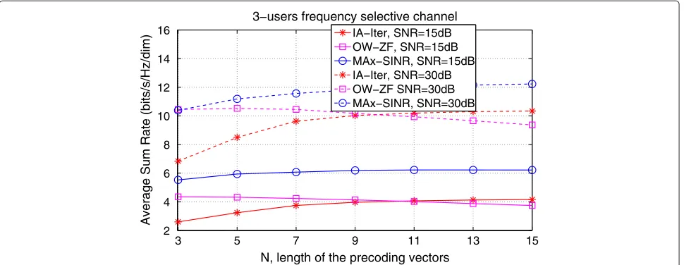
Figure 9Evolution of the average sum rate per dimension with the precoding vector length.
wider, and achieves 2 bits/s/Hz/dim over the TDMA at 30 dB. This is due to the suboptimality of the IA design in the low SNR region and its tendency to optimality in the high SNR region [4].
Next, Figure 9 evaluates the performance of the follow-ing designs: OW-ZF, IA-Iter, and Max-SINR, as a function of the precoding vectors sizes. At 15 and 30 dB, the OW-ZF outperforms the IA-Iter for N ≤ 9 and N ≤ 11. On the other hand, it can be observed that the two itera-tive designs IA-Iter and Max-SINR result in an increasing sum-rate with the vector sizes. However, the closed-form design OW-ZF results in a decreasing sum-rate with the vectors sizes. This means that OW-ZF is close to the opti-mal for sopti-mall precoding dimensions and starts moving away whenNincreases.
8 Conclusions
In this paper, we have introduced three optimized designs for the IA scheme in aK-user SISO IC. The first and the second try to optimize the precoding subspaces at the IA transmitters through a common diagonal matrix assum-ing an MMSE and ZF linear detector, respectively. The third assumes an MMSE linear detector and seeks the optimal precoding vectors within a predefined subspace at each transmitter. The first and the third designs referred to as W-MMSE and C-MMSE, respectively, require iter-ative algorithms to converge to their optimum, whereas the second design referred to as W-ZF is obtained from a closed-form solution. Comparing to other IA distributed designs, the proposed designs show a significant sum-rate performance improvement and much less computational complexity when the closed-form solution is applied. To enhance the sum-rate performance, we have introduced an orthogonalization of the precoding vectors in the
W-ZF design, which enables to achieve a trade-off between complexity and data rate.
Endnotes
aThis hypothesis is very optimistic, but it is taken by
many research works in the literature.
bIt is important to note that the Cholesky
decomposition, originally defined for a positive definite matrix, can be extended to the positive semi-definite case.
cThe IA schemes proposed for MIMO transmission
can also be used in SISO systems.
Appendix 1
Using thekth information rate expression in (24), the sum rate can be written as
R≡
K
k=1
log2|Xk| −log2|Yk| (28)
where
Xk =I+p K
j=1
¯
HkjCj H¯kjCj
H ,
andYk =I+p K
j=k
¯
HkjCj H¯kjCj
H
(29)
known to be dR=2∂R/C∗k. Details are given in [19]. Using the differential of log2|Xk|computed as
d log2|Xk| =trace
Using the following properties: trace AdBH = trace ATdB∗, d[trace(A)] = trace(dA), vec(dA) = dvec(X), and trace ATB= vec(A)T)vec(B), and referring to [19] that describes the first-order differential and the Jacobian matrix properties, we obtain
d log2|Xk| =
Thus, the gradient ofRw.r.t.C∗kis obtained as follows:
∇C(l)
The projected gradient algorithm requires firstly the com-putation of the gradient with respect tow˜
∂R(w)˜
LBk, respectively. The constraint, defined in (5), can be formulated as
Equation 35 defines the set of w˜ that satisfies the con-straint, thus, given the gradient, we project it on the constraint hyperplane and updatew˜ by
˜
whereμis a variable step size andp(w)˜ is the projected gradient defined as
The convergence towards the steady state is achieved either when
withis the tolerance factor for stopping the iterations or a maximum number of iterations is attained. In this algo-rithm, the step sizeμis a determining factor to ensure a faster convergence, thus, it must be judiciously selected. In [14], two line search methods are proposed: exact line search and inexact line search methods. In practice, most line searches are inexact, and many methods have been proposed. One is the backtracking method, which is employed for our design. It is very simple to implement and quite effective. Besides, the step size is updated at each iteration to satisfyw˜i>0 for alli.
Competing interests
The authors declare that they have no competing interests.
Acknowledgement
The authors would like to thank the ‘Institut Carnot Télécom et Société Numérique’ for funding the work of this paper.
Received: 16 October 2013 Accepted: 13 April 2014 Published: 15 May 2014
References
1. H Sato, On degraded Gaussian two-user channels. IEEE Trans. Inform. TheoryIT-24, 637–640 (1978)
2. A Carleial, Interference channels. IEEE Trans. Inform. Theory24, 60–70 (1978)
3. M Maddah-Ali, AS Motahari, AK Khandani, Communication over MIMO X channels: interference alignment, decomposition, and performance analysis. IEEE Trans. Inform. Theory54(8), 3457–3470 (2008)
4. VR Cadambe, SA Jafar, Interference alignment and degrees of freedom of the K-user interference channel. IEEE Trans. Inform. Theory54(8), 3425-3441 (2008)
5. AS Motahari, SO Gharan, MA Maddah-Ali, AK Khandani, Real interference alignment: exploiting the potential of single antenna systems. arXiv:0908.2282
6. SW Choi, SA Jafar, S-Y Chung, On the beamforming design for interference alignment. IEEE Commun. Lett.13(11), 847–849 (2009) 7. K Gomadam, VR Cadambe, SA Jafar, Approaching the capacity of wireless
networks through distributed interference alignment, inProc. of IEEE Global Communications Conference, GLOBECOM(IEEE New Orleans, USA, 2008)
8. SW Peters, RW Heath, Interference alignment via alternating
minimization, inProc. of IEEE International Conference on Acoustics, Speech and Signal Processing, ICASSP, (2009), pp. 2445–2448
9. I Santamaria, O Gonzalez, R Heath, S Peters, Maximum sum-rate interference alignment algorithms for MIMO channels, inProc. of IEEE Global Communications Conference, GLOBECOM(IEEE Miami, USA, 2010) 10. C Yetis, T Gou, SA Jafar, AH Kayran, On feasibility of interference alignment
in MIMO interference networks. IEEE Trans. Signal Process.58(9), 4771–4782 (2010)
11. H Sung, S Park, K Lee, I Lee, Linear precoder designs for K-user
interference channels. IEEE Trans. Wireless Commun.9(1), 291–300 (2010) 12. D Serre,Matrices: Theory and Applications, Second Edition. (Springer,
New York, 2010)
13. NJ Higham,Analysis of the Cholesky Decomposition of a Semi-Definite Matrix. (Oxford University Press, 1990), pp. 161–185
15. D Kim, M Torlak, Optimization of interference alignment beamforming vectors. IEEE J. Selected Areas Commun.28(9), 1425–1434 (2010) 16. H Shen, B Li, M Tao, Y Luo, The new interference alignment scheme for
the MIMO interference channel, inWireless Communications and Networking Conference (WCNC), 2010 IEEE(Sydney, Australia, 2010), pp. 1–6 17. PW Wolniansky, GJ Foschini, G Golden, RA Valenzuela, V-blast: an
architecture for realizing very high data rates over the rich-scattering wireless channel, inSignals, Systems, and Electronics, 1998. ISSSE 98. 1998 URSI International Symposium On(IEEE Pisa, 1998), pp. 295–300 18. M Shen, A Host-Madsen, J Vidal, An improved interference alignment
scheme for frequency selective channels, inProc. of IEEE International Symposium on Information Theory, ISIT(Toronto, ON, 2008), pp. 6–11 19. J Magnus, H Neudecker,Matrix Differential Calculus with Applications in
Statistics and Econometrics. (Wiley, Chichester, revised version 2007)
doi:10.1186/1687-1499-2014-79
Cite this article as:Fadlallahet al.:Interference alignment for a multi-user SISO interference channel.EURASIP Journal on Wireless Communications and
Networking20142014:79.
Submit your manuscript to a
journal and benefi t from:
7Convenient online submission 7 Rigorous peer review
7Immediate publication on acceptance 7 Open access: articles freely available online 7High visibility within the fi eld
7 Retaining the copyright to your article