R E S E A R C H
Open Access
Amplify-forward relaying for multiple-antenna
multiple relay networks under individual power
constraint at each relay
Yasser Attar Izi
*and Abolfazl Falahati
Abstract
This article considers the design of an optimal beamforming weight matrix of multiple-antenna multiple-relay networks. It is assumed that each relay utilizes the amplify and forward strategy, i.e., it multiplies the received signal vector by a matrix, dubbed the relay weight matrix, and forwards the resulting vector to the destination.
Furthermore, we assume that the source and the destination have the same number of antennas and that each transmit antenna is virtually paired to a different destination antenna. The relay weight matrices are concurrently designed to optimize the mean square error (MSE) criterion at the destination, assuming each relay node is subject to a power constraint. Accordingly, it is demonstrated that this problem can be cast as a convex optimization problem in which the individual power constraints are tackled by employing the method of Lagrange multipliers in two stages. First, the relay gain matrix is computed analytically in terms of Lagrange dual variables, thereby converting the original problem into a scalar optimization problem. Then, these scalar variables are computed numerically. The proposed scheme is evaluated through simulation with various numbers of relays and antennas to obtain MSE and bit error rate (BER) metrics and it is shown that the resulting MSE and BER achieved through using the proposed method outperforms that of MMSE-MMSE method introduced by Oyman et.al., which is regarded as the best known method for the underlying problem.
Keywords:co-operative communication, multiple-antenna multiple-relay networks, convex optimization, amplify and forward relaying
1. Introduction
It is well established that in most cases relaying techni-ques provide considerable advantages over direct trans-mission, provided that the source and relay cooperate efficiently. The choice of relay function is especially important as it directly affects the potential capacity benefits of node cooperation [1-5]. In this regard, two relaying methods, amplify-forward (AF) [6,7] and esti-mate-forward [8,9], are extensively addressed in the lit-erature. As the names imply, the former just amplifies the received signal but the latter estimates the signal with errors and then forwards it to the destination.
It has been shown that increasing the number of relays has the advantage of increasing the diversity gain and flexibility of the network; however, it renders some
new issues to arise [10]. For instance, the relaying algo-rithm and power allocation across relays should be addressed is such cases. Relay selection [11,12] and power allocation [13,14] are two well-known methods when dealing with the power management issues.
The capacity and reliability of the relay channel can be further improved by using multiple antennas at each node. The use of relays together with using multiple antennas has made it a versatile technique to be used in emerging wireless technologies [15-20]. Relaying strate-gies for the multi-antenna multiple-relay (MAMR) net-works is more challenging than single-antenna networks, since in addition to scaling and phase opera-tions, matrix operations should also employed at the relays.
AF MIMO relay systems have drawn considerable attention in the literature due to their simplicity and ease of implementation. In this regard, a plethora of * Correspondence: [email protected]
Department of Electrical Engineering, Iran University of Science and Technology, Tehran, Iran
works are devoted to finding a proper relaying strategy for AF MAMR networks. In [21], the idea of linear dis-tributed multi-antenna relay beamforming is introduced where each relay performs a linear reception and trans-mission in addition to output power normalization. In
this article, Ksingle antenna transmitted independent
data streams to their respected single antenna receivers. The linear operations suggested in this article are matched filter, zero forcing, and minimum mean square error (MMSE). They are briefly called MF-MF, ZF-ZF, and MMSE-MMSE schemes, respectively. In [22], a method based on QR decomposition is suggested which works better than the ZF-ZF scheme. Combinations of various schemes are also considered in [22]. For exam-ple in ZF-QR scheme, relays perform ZF algorithm in reception and QR algorithm (channel triangulation) in transmission.
In [23], the so-called incremental cooperative beam-forming is introduced and it is shown that it can achieve
the network capacity in the asymptotic case of large K
with a gap no more than O(1/log(K)). However, this
method is not suited when few relays are incorporated since this method only works properly when the num-ber of relays tends to infinity.
In [24], a wireless sensor network that is composed of some multi-antenna sensors aimed to transmit a noisy measurement vector parameter to the fusion centre is formulated as a MAMR network. Moreover, it is assumed that the second hop associated with the result-ing MAMR network has a diagonal channel matrix and the destination noise is small enough to be ignored. The current manuscript is actually an extension of [24] since neither the channel matrices need to be diagonal nor the destination noise is restricted to be zero.
In [25], it is shown that an MAMR network with single-antenna source and destination can be transformed to a single-antenna multiple relay (SAMR) network by per-forming maximal ratio combining at reception and trans-mission for each relay nodes. This enables the network beamforming introduced in [14] to be readily employed.
In [26], by using ZF-ZF scheme, an MAMR network withM single-antenna source-destination pairs is
trans-formed toM SAMR networks to which
network-beam-forming proposed in [14] is applied.
In [27], the relay gain matrices are obtained by maxi-mizing the MSE at destination restricting the received power at the destination. In [28], a linear relaying scheme for an MAMR network fulfilling the target SNRs on different independent substreams transmitted from each source antennas is proposed and the power-efficient relaying strategy is derived in closed form. In [29], a nearly optimal relaying scheme is proposed to maximize the mutual information between the source and the destination under total relay power constraint.
In this article, the problem of MAMR network with multiple antennas at source and destination with indivi-dual relays power constraints is formulated as a convex optimization problem. The optimum relay gain matrices are obtained by solving the optimization problem using Lagrange dual variables method. This relays gain
matrices are obtained in terms of K scalar variables
where Kis the number of relays. Then those variables
are computed numerically. As noted before, the articles that investigate this configuration either suggest the relay gain matrix heuristically or concern another con-straint such as a limited power concon-straint at the destina-tion, the destination quality of service or the sum power of relays. In our opinion, the limited power for each relay is a more realistic assumption, because each relay in the network has its own power supply and unused power for each relay cannot be used by other relays. In the same manner as [26-29], complete CSI is considered to be available for optimum relay design. The optimiza-tion can be performed at the destinaoptimiza-tion, and then the processing results are fed back to the relays. Although the closed form formula is not obtained but a para-metric relation form of the relay gain matrices are derived. These parameters can be calculated either numerically or heuristically. A simpler form of the relay gain matrices is derived for the two relay case. The initial works on this issue are first addressed in [30] while the optimal solution is not fully treated there.
2. System model
Figure 1 illustrates a typical MAMR relay network sys-tem in which there are Msingle-antenna sources, trying
to send independent data streams through K
multi-antenna relays to their affiliated single-multi-antenna
Figure. 1
destinations. In fact, the aim is to send independent data streams from each source antenna to the corresponding single-antenna destination. Thus, each single-antenna destination can merely apply a simple scaling to its received signal and the integral part of the interference cancellation process must be performed at multi-antenna relays.
It is assumed that the ith relay has Ni antennas.
Hence, the transmission occurs in two hops. During the first hop, the transmitter broadcasts the desired signal to the relays. Then, throughout the second hop, each relay applies a weight matrix to the received signal vec-tor and retransmits it to the destination.
We considerxas anM× 1 vector whose elements are
independent zero mean Gaussian random variables with covariance matrixE(xxH) =PsIM Thus, the received
sig-nal vector at theith relay can be represented as
yi=Hix+ni, (1)
whereniis a Ni × 1 Gaussian noise vector, represent-ing the input noise vector at theith relay with the cov-ariance matrix EniniH
=PniINi where INi denotes the
identity matrix and Pni is the noise power associated
with each entry of ni . Hi is a known Ni × M matrix
with complex elements, representing the channel gain matrix between the transmitter and theith relay. More-over, (.)H is Hermitian operation. Assuming theith relay multiplies its received signal by a weight matrix Wiand forwards the resulting vector,xi, to the destination, thus
xi=Wiyi=Wi(Hix+ni)=WiHix+Wini. (2)
where Pout
i is the average transmit power which is
assumed to be lower than Pri, considering . is
frobe-nius norm. Thus, referring to Figure 1, it follows
y=K
whereGi is theM×Ni channel gain matrix between
theith relay and the destination whose entries are com-plex and assumed to be known completely at the
desti-nation. Also, n is an M × 1 zero-mean noise vector
whose entries are of power Pnd Finally,ni fori = 1,2,..., K andnare assumed to be statistically independent.
Furthermore, as it is noted earlier, a scalar operation is merely done at each destination. In other words, the
weight matrices Wi for i = 1,2,..., Kare computed so
that the received vector y is a scaled unbiased
estimation of the transmitted vectorx. Note that when sources and destinations are equipped with multiple antennas, joint precoder and reception matrices must be concurrently designed along with the relay matrices. However, this is a completely different problem which is out of the scope of the current work. It should be emphasised that since there is a correspondence between each source and its affiliated destination, the number of sources and destinations remains the same.
3. Optimization problem
In this section, we aim at addressing the problem for-mulation using the MSE criterion, assuming each relay is subject to an individual power constraint. In what fol-lows, we first formalize and then present the proposed approach to get the optimal solution. Referring to (3) and (4), the optimization problem can be represented as
where his a positive constant value which affects the signal power and consequently the resulting SNR at the destination. The choice ofhwould ensure a certain tar-get SNR at the destination as follows [31]:
η= γtPn
Ps
(6)
wheregtis the target SNR. Although increasing hcan increase the SNR, there is a threshold beyond which the
choice of h cannot improve the SNR and merely
increases the noise power [27]. Finding the best value
for his a difficult task when relying upon analytical
methods; one can think of numerical methods to tackle a relation close to optimal solution. Section 5 aims at addressing this issue. In what follows we assumehis a known parameter. Thus, from (5) the objective function can be expanded as
ξ= Ex,n1,...,nK,n
⎧
Without loss of generality, Pscan be set equal to one.
The Lagrangian [32] associated with (9) can then be written as
wherelifor i= 1,...,Kare the corresponding Lagrange multipliers. The Lagrangian can be expressed as
L(W1,W2,. . .,WK,λ1,λ2,. . .,λK)= [33] is used in the third term in (11) and the fact that A=|vec(A)| from [33] is used in the remaining terms.
Furthermore, using the fact that vec(AXB) = (BT⊗A) vec(X) from [33], the Lagrangian can then be rewritten as
To simplify (12), the following matrix and vectors are defined:
We can reformulate the Lagrangian (12) as
L =
To obtain the optimumwps, the differentiation of the Lagrangian with respect to wp (p= 1,2...,K) has to be set to zero:
∂L
Setting the derivation to zero, it can be concluded that
∂L
If the following parameters are defined as follows:
wo= Kdefine as
(A)pp
Hence the matrixAis defined as
Therefore, the relation (16) can be represented simply
Then, by substituting (21) into (14) one can readily arrive at Lagrange dual problem [32], consideringlifor i= 1,...,Kare non-negative values. Thus, maximizing the obtained dual object function yields the optimal values for the corresponding Lagrange coefficients. However, this dual problem is too complicated to differentiate, thus does not lead to an analytical solution. Hence, a numerical method, called the active set method [34], is employed to compute the Lagrange multipliers.
It is worth mentioning that the dual problem involves
just Kscalar variables, however, the primary problem
contains K unknown matrices each of size Ni × Ni.
Thus, relying on dual problem, results in a simplification which can be effectively addressed through using the aforementioned numerical method.
Inserting the obtained w from (21) to (14), the
Lagrange dual problem can be written as ⎧
From KKT condition [32], if li is found to be
non-zero, theith relay has to transmit with its full power. In the same approach as [35] in which the precoder is designed for a MIMO transmitter using the Lagrangian method, Lagrange multipliers are found by solving a set of nonlinear equations. In these equations, the multipli-cations of Lagrange multipliers with their corresponding inequality constraints have to be set to zero concur-rently.
In [32], this is not solved but a value is suggested heuristically for the li and the output is then normal-ized to the transmitter output power. Here, such values are determined numerically.
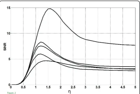
4. Discussion on the parameter h
Increasing the parameterhin (5) not only improves the received signal power, but it also renders the noise power to be increased, thereby the received signal-to-interference and noise ratio (SINR) may not be
improved ash exceeds a certain threshold. Note that
the optimal value of hcannot be derived analytically.
This motivated us to rely upon some numerical
meth-ods to indicate how h may affect both the received
SINR and bit error rate (BER) which are served as per-formance functions in the current study. Specifically, two different approaches are exploited in our numerical study. In the first part of our study, the resulting
received SINR against hfor many realizations of
chan-nel matrices and for various values of transmitted SNR is computed under different network’s configurations. Note that in this case, the transmitted SNR is defined as
TSNR = Ps/Pn and consequently the received SINR is
computed as
where“diag(A)”represents a diagonal matrix with the
same diagonal entries as matrix A. Figures 2 and 3
represent the sensitivity of the received SINR againsth for 2 and 4 relay networks, respectively. The simulation is performed for different channel realizations consider-ing the transmitted SNR (TSNR) is set to 12 dB.
It can be observed that for each channel realization,
there is an optimum value forhthat is dependent upon
the instantaneous first and second hop channel matrices.
Thus, the optimum value ofhis a random variable for
each network configuration as well as TSNR. The
Figure. 2
probability density function (PDF) ofhcan be estimated through using Mont Carlo simulation method. In
Fig-ures 4 and 5, the estimated PDF for the optimum his
depicted for a network of two antennas, two relays and four antennas, four relays, respectively. It can also be observed that the PDFs are very thin, i.e., a low variance value. Thus, we can select the mean value of the
opti-mum value of hfor simulation purposes. So, for each
network configuration, the best value of hcan be deter-mined for the performance evaluation.
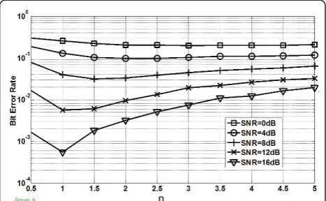
Furthermore, for different configurations of the relay network, the BER at the destination is computed against hfor various values of SNRs. It can be seen that at the beginning, increasinghresults in decreasing BER. How-ever, as it increases beyond a certain value, the BER increases. Accordingly, Figure 6 depicts the BER against
hfor a network with two relays each having two
anten-nas. It can be seen that the selectedhfrom this diagram
is in agreement with the value that is obtained from Fig-ure 4.
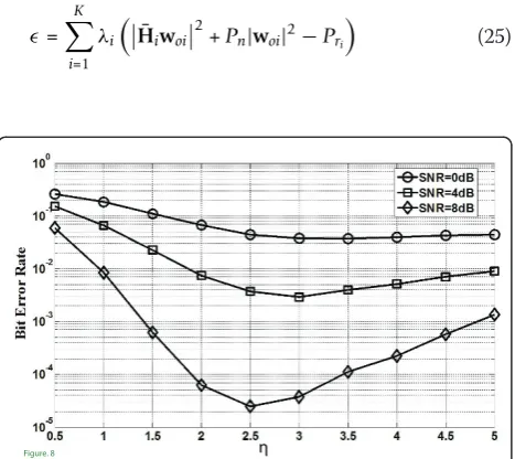
Also, Figures 7 and 8 are provided for various network configurations with different number of relays and antennas.
Referring to the results, it can be observed that at
each SNR point, there is an h in which the resulting
BER is minimized. Moreover, results show that there is
a close agreement between the optimum value of h
from BER curves to that obtained from the estimated
PDF for h. The obtained values are employed later in
the simulation results provided in Section 6.
5. The proposed algorithm implementation procedure
The material proposed in the previous sections can be summarized for system implementation as follows.
Channel estimation has to be performed primarily. The channel estimation for AF relaying is considered in related literatures [36,37]. It is assumed that the estimation and
Figure. 4
Figure 4The estimated histogram for the optimum value ofh considering two-relay network each having two antennas and two source-destination pairs.
Figure. 5
Figure 5The estimated histogram for the optimum value ofh considering four-relay network each having four antennas and four source-destination pairs.
Figure. 6
Figure 6BER at destination with two relays each having two antennas for various values ofhand SNRs.
Figure. 3
transmission of channel matrices are error free. Assuming a slow fading channel, the first and second hop channels can be modeled as block fading channels and it can be assumed that it does not change during the block. The block can be a fraction of coherent time of the channel.
Knowing the TSNR, the best value forhcan be
deter-mined by the methods introduced in Section 4.
Further-more, A and f are computed from (19) and (17),
respectively. Then,wcan be computed from Equation
(21) (wis a function ofli’s). Insertingwto (22), an object function withKscalar unknown variables is obtained. This function has to be maximized with respect to the set of non-negativeli’s. Then using the active set method that does not need the closed loop form of the gradient is used to find the optimum values ofli’s. The stopping criterion is are the difference between the primary object function and the dual object function or
=
K
i=1
λiH¯iwoi2+Pn|woi|2−Pri
(25)
Thus, the algorithm at the boundary of each block is as follows.
Initialization: set lito an arbitrary start value for i=
1,...,K,
iterate: computeA,fandw
Compute: =
K
i=1
λiH¯iwoi
2
+Pn|woi|2−Pri
(26)
IfÎ <Î0end,
else modifylifor i= 1,...,K, goto iterate,
whereÎ0is a predetermined constant value that can be chosen arbitrary according to specific design accuracy.
Modification ofli in the last line of the algorithm is performed based on the Active Set method [34]. In this method, during each step the gradient of the cost func-tion is estimated using three points in the space. The
MATLAB function “fmincon”can be used to implement
this method.
6. Simulation results
To confirm the superiority of the proposed schemes over MMSE-MMSE and ZF-ZF method, their average BER and MSE are compared by varying the number of relay nodes, K, and the number of relay antennasN. It is also assumed that the input noise power at the des-tination and the relays are the same. The channel matrices are generated independently during subse-quent iterations. It is further assumed that the first and the second hop channels for all relays are known perfectly. Networks with various numbers of nodes and antennas are simulated and the average BER and the MSE parameter are used as the performance metrics and they are compared with MMSE-MMSE and ZF-ZF methods. Independent un-coded QPSK modulated symbol streams are transmitted from each of the source antennas.
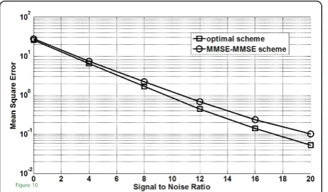
The average BER and MSE versus SNRtforN=M=
3 for a two relay network are shown in Figures 9 and
Figure. 8
Figure 8BER at destination with four relays each have four antennas for various values ofhand SNRs.
Figure. 9
Figure 9BER at destination with two relays each having three antennas.
Figure. 7
10, respectively. From these figures, it is found that the proposed scheme outperforms ZF-ZF and MMSE-MMSE schemes in all the examined cases.
For the second network configuration, it is assumed
that N = M = 4, and the number of relays is 2. The
average BER and MSE for three mentioned methods are depicted in Figures 11 and 12, respectively. It can be easily observed that the proposed optimum scheme out-performs both MMSE-MMSE and ZF-ZF methods.
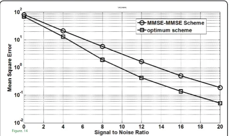
Finally, networks with 4 and 6 relays are simulated. In the former setup each relay has four antennas and in the later case three antennas. For this case, The BER and MSE versus SNR are depicted in Figures 13, 14, 15, and 16.
In these cases too, the simulation results reveal that the optimum scheme outperforms the other two meth-ods. Furthermore, the complexity observed by the pro-posed optimum method although seems to be a bit higher than MMSE-MMSE scheme, but provides a solu-tion that would reduce the power consumpsolu-tion by approximately 3 dB.
7. Conclusion
A relay network with multiple relay each having multi-ple antennas is considered. The relay matrices are found by solving an optimization problem. In this problem, the MSE at the destination is minimized and the individual relay output power considered as constraint. The Lagrange dual problem is then obtained to compute the Lagrange dual variables numerically. Solving Lagrange dual problem (22) is simpler than the primary problem (9). This is because, solving Lagrange dual problem
requires the calculation ofK scalar unknown variables
but in primary problem case, K unknown N × N
matrices needs to be computed. So, the dimension of
the problem decreasesN×Ntimes.
Two numerical methods based upon SINR and BER are introduced to obtain the optimum value ofhthat is employed for the actual simulation of the proposed opti-mum scheme.
The system with the proposed optimum, MMSE-MMSE and ZF-ZF schemes, is simulated and the aver-age BER as well as MSE at destination are obtained. The
Figure. 10
Figure 10MSE at destination with two relays each having three antennas.
Figure. 11
Figure 11BER at destination with two relays each have four antennas.
Figure. 12
Figure 12MSE at destination with two relays each have four antennas.
Figure. 13
results show that the proposed optimum scheme out-performs MSE-MSE and ZF-ZF schemes by a good mar-gin. Indeed, analytical computation of Lagrange dual
variables and considering normalization parameter has
the optimization problem variable can be considered for future investigations.
Appendix
Two relays network case
For two relay network further simplification can be per-formed. Rewriting (16)
⎧ ⎨ ⎩
T1HT1+λ1H¯H1H¯1+PnG¯H1G¯1+Pnλ1I
w1+T1HT2w2=ηf1∗
T2HT2+λ2H¯H2H¯2+PnG¯H2G¯2+Pnλ2I
w2+T2HT1w1=ηf2∗ (27)
and removingW2in that will lead to ⇒w1=
⎡ ⎢ ⎣
T1HT2
−1
T1HT1+λ1H¯
H
1H¯1+PnG¯ H
1G¯1+Pnλ1I
−T2HT2+λ2H¯
H
2H¯2+PnG¯ H
2G¯2+Pnλ2I
−1
PrT2HT1
⎤ ⎥ ⎦
−1
⎡ ⎣
T1HT2
−1 ηf1∗
−T2HT2+λ2H¯
H
2H¯2+PnG¯ H
2G¯2+Pnλ2I
−1 ηf2∗
⎤ ⎦.
(28)
Recalling defined parameters from (13) and some manipulation we can derive
w1=
ηH1∗⊗G1H
H2T⊗H2 H1T⊗H1−
H2HH2T
⊗G2G2H H1HH1T
⊗G1G1H −1
vecH2H2−G2G2HH2HH2
(29)
w2=η
H2∗⊗G2H
H1T⊗H1 H2T⊗H2−H1HH1 T
⊗G1G1H H2HH2 T
⊗G2G2H
−1
vecH1H1−G1G1HH1HH1.
(30)
Where
H2=
H2HH2+PnI
,
H2=
G2G2H+λ2I
,
H1=
H1HH1+PnI
,
H1=
G1G1H+λ1I
,
(31)
Competing interests
The authors declare that they have no competing interests.
Received: 27 May 2011 Accepted: 17 February 2012 Published: 17 February 2012
References
1. A Sendonaris, E Erkip, B Aazhang, User cooperation diversity, Part I: system description. IEEE Trans Commun.51(11), 1927–1938 (2003). doi:10.1109/ TCOMM.2003.818096
2. D Chen, JN Laneman, Modulation and demodulation for cooperative diversity in wireless systems. IEEE Trans Wirel Commun.5(7), 1785–1794 (2006)
3. JN Laneman, DNC Tse, GW Wornell, Cooperative diversity in wireless networks: efficient protocols and outage behavior. IEEE Trans Inf Theory.
50(12), 3062–3080 (2004). doi:10.1109/TIT.2004.838089
Figure. 15
Figure 15BER at destination with six relays each having three antennas.
Figure. 16
Figure 16MSE at destination with six relays each having three antennas.
Figure. 14
4. G Kramer, M Gastpar, P Gupta, Cooperative strategies and capacity theorems for relay networks. IEEE Trans Inf Theory.51(9), 3037–3063 (2005). doi:10.1109/TIT.2005.853304
5. KA Yazdi, H El Gamal, P Schniter, On the design of cooperative transmission schemes. inProceedings of 41st Allerton Conference on Communication, Control, and ComputingMonticello, IL 1576–1585 (October 2003) 6. T Issariyakul, V Krishnamurthy, Amplify-and-forward cooperative diversity
wireless networks: model, analysis, and monotonicity properties. IEEE/ACM Trans Netw.17(1), 225–238 (2009)
7. RU Nabar, FW Kneubuhler, H Bölcskei, Performance limits of amplify-and-forward based fading relay channels. inProceedings of IEEE Int Conf Acoustics, Speech and Signal Processing, Montreal.4, 565–568 (May 2004) 8. I Abou-Faycal, M Médard, Optimal uncoded regeneration for binary
antipodal signalling. inProceedings of IEEE Int Conf on Communications, Paris, France.2, 742–746 (2004)
9. KS Gomadam, SA Jafar, Optimal relay functionality for SNR maximization in memoryless relay networks. IEEE J Sel Areas Commun.25(2), 390–401 (2007)
10. L-L Xie, PR Kumar, Multisource, multidestination, multirelay wireless networks. IEEE Trans Inf Theory.53(10), 3586–3595 (2007) 11. E Beres, R Adve, On selection cooperation in distributed networks, in
Proceedings of IEEE 40th Conf Info Sci and Sys, (CISS 2006), Princeton, NJ, (March 2006), pp. 1056–1061
12. Y Zhao, R Adve, TJ Lim, Improving amplify-and-forward relay networks: optimal power allocation versus selection. IEEE Trans Wirel Commun.6(8), 3114–3123 (2007)
13. M Chen, S Serbetli, A Yener, Distributed power allocation strategies for parallel relay networks. IEEE Trans Wirel Commun.7(2), 552–561 (2008) 14. Y Jing, H Jafarkhani, Network beamforming using relays with perfect
channel information, inProceedings of Int Conf Acoustics, Speech, Signal Processing (ICASSP), vol. 3. (Honolulu, HI, 2007), pp. 473–476
15. X Tang, Y Hua, Optimal design of non-regenerative MIMO wireless relays. IEEE Trans Wirel Commun.6(6), 1398–1407 (2007)
16. B Wang, J Zhang, A Host-Madsen, On the capacity of MIMO relay channels. IEEE Trans Inf Theory.51(1), 29–43 (2005)
17. B Khoshnevis, W Yu, R Adve, Grassmannian beamforming for MIMO amplify-and-forward relaying. IEEE J Sel Areas Commun.2(8), 1397–1407 (2008)
18. Y Fan, J Thompson, A Adinoyi, H Yanikomeroglu, Space diversity for multi-antenna multi-relay channels. inProceedings of Eur Wireless Conf(2006). Athens, April 2-5 2006
19. Y Fan, J Thompson, MIMO Configurations for relay channels: theory and practice. IEEE Trans Wirel Commun.6(5), 1774–1786 (2007)
20. Y Fan, A Adinoyi, JS Thompson, H Yanikomeroglu, Antenna combining for multi-antenna multi-relay channels. Eur Trans Telecommun.18(6), 617–626 (2007). doi:10.1002/ett.1231
21. ?Ö? Oyman, AJ Paulraj, Power-bandwidth tradeoff in dense multiantenna relay networks. IEEE Trans Wirel Commun.6(6), 2282–2293 (2007) 22. H Shi, T Abe, T Asai, H Yoshino, Relaying schemes using matrix
triangularization for MIMO wireless networks. IEEE Trans Commun.55(9), 1683–1688 (2007)
23. SO Gharan, A Bayesteh, AK Khandani, Asymptotic analysis of amplify and forward relaying in a parallel MIMO relay network, inProceedings of 45th Annual Allerton Conf on Comm., Control, and Computing, Monticello, IL, (September 2007), pp. 89–95
24. J Xiao, S Cui, Z-Q Luo, AJ Goldsmith, Linear coherent decentralized estimation. IEEE Tran Signal Process.56(2), 757–770 (2008)
25. YA Izi, A Falahati, On the cooperation and power allocation schemes for multiple-antenna multiple-relay networks, inProceedings of Int Conf Wireless and Mobile Commun (ICWMC), Cannes/La Bocca, French, (August 23–29 2009), pp. 44–48
26. A Falahati, YA Izi, Power allocation for zero forcing scheme in multiple antenna multiple relay networks, inProceedings of 5th international symposium on telecommunications (IST2010), Tehran, Iran, (4–6 December 2010), pp. 297–301
27. AS Behbahani, R Merched, AM Eltawil, Optimizations of a MIMO relay network. IEEE Trans Signal Process.56(10), 5062–5073 (2008)
28. W Guan, H Luo, W Chen, Linear relaying scheme for MIMO relay system with QoS requirements. IEEE Signal Process Lett.15, 697–700 (2008)
29. Y Fu, L Yang, W-P Zhu, A nearly optimal amplify-and-forward relaying scheme for two-hop MIMO multi-relay networks. IEEE Commun Lett.14(3), 229–231 (2010)
30. YA Izi, A Falahati, AF relaying for multiple antenna multiple relay networks under individual power constraint at each relay. inProceeding of 3rd International Symposium on Applied Sciences in Biomedical and Communication Technologies (ISABEL)1–5 (2010). Rome, 7-10 November 31. N Khajehnouri, AH Sayed, Distributed MMSE relay strategies for wireless
sensor networks. IEEE Trans Signal Process.55(7), 3336–3348 (2007) 32. SP Boyd, L Vandenberghe, in Convex Optimization, (Cambridge University
Press, Cambridge, 2004) http://www.stanford.edu/~boyd
33. KB Petersen, MS Petersen, The Matrix Cookbook. Technical University of Denmark, October 2008. http://www2.imm.dtu.dk/pubdb/views/ edoc_download.php/3274/pdf/imm3274.pdf
34. J Nocedal, S Wright, Numerical Optimization, 2nd edn. (Springer, New York, 2006). ISBN:0387303030
35. M Joham, W Utschick, J Nossek, Linear transmit processing in MIMO communications systems. IEEE Trans Signal Process.53(8), 2700–2712 (2005) 36. F Gao, T Cui, A Nallanathan, On channel estimation and optimal training
design for amplify and forward relay networks. IEEE Trans Wirel Commun.7, 1907–1916 (2008)
37. S Sun, Y Jing, Channel training and estimation in distributed space-time coded relay networks with multiple transmit/receive antennas, in Proceedings of IEEE WCNC, Sydney, Australia, (18–21 April 2010), pp. 1–6
doi:10.1186/1687-1499-2012-50
Cite this article as:Izi and Falahati:Amplify-forward relaying for multiple-antenna multiple relay networks under individual power constraint at each relay.EURASIP Journal on Wireless Communications and Networking20122012:50.
Submit your manuscript to a
journal and benefi t from:
7Convenient online submission
7Rigorous peer review
7Immediate publication on acceptance
7Open access: articles freely available online
7High visibility within the fi eld
7Retaining the copyright to your article