The Positioning system for KM3NeT
Giorgio Riccobene1,* for the KM3NeT Collaboration1INFN-LNS, Via S-Sofia 62, I-95123 Catania, Italy
Abstract. The paper describes the implementation of a hybrid positioning system based on tilt and compass sensors, integrated into an electronic board, and an acoustic positioning system to be installed aboard KM3NeT. The acoustic system will be capable to fulfil detector relative and absolute positioning, to provide data for cross-fertilisation with Earth and Sea science (bio-acoustics and environmental monitoring) and to allow studies for neutrino acoustic detection. Tilt and Compass boards installed in each optical module provide information about the DOM orientation.
1 Introduction
Acoustic detection offers a wide range of applications and opportunities for the KM3NeT telescope, with detector positioning system considered as the mandatory goal. The implementation of the acoustic system in KM3NeT is based on technologies successfully operated in KM3NeT (in particular within the framework of the pilot projects ANTARES [1], NEMO Phase II [2] and PPM-DU [3]) andon the knowledge of available commercial systems. KM3NeT Phase 1 will consist of 24 Detection Units deployed in Capo Passero (ARCA Phase 1) and 7 DUs deployed in Toulon (ORCA Phase 1) [4]. Each DU carries 18 Digital Optical Modules (DOMs). The vertical distance between DOMs is 36 m in ARCA and 9 m in ORCA. Horizontal distances among the DU are about 90 m in ARCA and 20 m in ORCA. In this first stage all DOMs will be equipped with acoustic receivers in order to extensively test the relative acoustic detection system and to develop a “hybrid positioning system” that will use acoustic positioning system data, compass/tilt data and current meters data. This information will be, later, used to develop also a “DU mechanical shape model” that will be used to refine reconstruction of DOM positions. A building block of KM3NeT will consist of approximately 115 DUs like the ones deployed for Phase 1. On the base of experience of Phase 1, a further effort will be carried out to reduce the number of acoustic receivers. The proposed relative acoustic system relies on “all data to shore” philosophy. This means that acoustic data acquired by the acoustic receivers are continuously digitized and sent to shore, thus analysed with a dedicated farm of PCs. This choice avoids the use of off-shore electronics for signal identification, reducing power consumption and costs, improving the system reliability and versatility. Two kinds of technologies for acoustic sensors are available and will be installed aboard the DUs: An “external” digital hydrophone, installed in each DU base, and “internal” digital piezoelectric-sensor
(elsewhere indicated as “piezo in the DOM”), installed inside the DOM. Both technologies have been successfully tested. A major step of KM3NeT, with respect to mentioned previous technologies, is the use of digital acoustic receivers that sample the analogue piezoelectric signal and provide a PCM-like protocol (pulse code modulation, such as AES-EBU) to the Central Logic Board installed in each DOM and DU Base. The use of AES protocol simplifies interface with CLB and permits the use of standard audio libraries. It is worth mentioning that using the described system allows sharing of acoustic data with the Earth and Sea Science Community for several research items: marine monitoring, biology, geophysics, oceanography, et cetera.
2 The Acoustic Positioning System
Two different acoustic positioning systems (APS) are needed to provide mandatory information during the deployment and the operation phases of the KM3NeT telescope. During the deployment phase, the so-called navigation and absolute acoustic positioning system (NAAPS) must provide the position of the telescope’s mechanical structures, in a geo-referenced coordinate system, with an accuracy of about 2 meters. This is important for a safe deployment of the mechanical structures. The detector field is geo-referenced by the NAAPS using auxiliary acoustic systems such as commercial Ultra short Baseline -USBL- positioning systems (used in ARCA) and customisation of commercial LBL system (Ramses-Ixblue, used in ORCA). A relative acoustic positioning System (RAPS) has been designed and (so far, partially) operated within KM3NeT to determine the positions of the DUs and DOMs (and their changes in time) in the geo-referenced field. In fact, in order to effectively reconstruct the muon tracks via the optical Cherenkov technique, the DOM’s coordinates must be known (in a known reference system) with accuracy of about (and possibly better than) 20 cm. Moreover, in deep sea, the mechanical structures holding the optical modules move under the effect of currents, thus their positions must be determined and monitored. The RAPS must be able to determine DOM’s position continuously via triggered emission of acoustic signals whose repetition rate is of one every few minutes. This interval ensures optimal position reconstruction, given the slow movements of DOMs underwater. The RAPS uses an auto-calibrating Long Baseline system of hydrophones and acoustic emitters displaced in the geo-referenced field. During the telescope operation phase, the data from the relative acoustic positioning system are used (in combination with compass and tilt, pressure, current and sound velocity data) to recover the positions of digital optical modules (DOMs) in deep sea. The KM3NeT Relative APS is composed by three main sub-systems: 1) an array of acoustic receivers (hydrophones and piezo sensors) rigidly connected to the telescope mechanical structures; 2) a so-called Long Base-Line (LBL) of acoustic transmitters (beacons) and receivers, anchored on the seabed in geo-referenced positions; 3) a farm of PCs for the acoustic data analysis on the shore. The positions of the acoustic receivers are calculated on-shore by measuring the ToF (Time of Flight) of the LBL beacons signals on the acoustic receivers, thus determining, via multiple triangulation, the position of the acoustic receivers with respect to the geo-referenced RAPS LBL. The emission signals of acoustic transmitters (beacons, Fig. 1 left) will be set in the range of frequencies 20÷40 kHz, where acoustic signals can effectively propagate in water: at 2 km distance the amplitude for a 180 dB re1 Pa, 32 kHz tone is about 110 dB re1 Pa, and it can be easily recognised by the acoustic receivers of the telescope. Since the whole receiver’s array is synchronous with the detector master clock (thus with the GPS time delivered from shore), the proposed RAPS can perform precise ToF measurement. ToF measurements between different LBL beacons and receivers (hosted in the DU base and CB) will be used to perform LBL auto-calibration in deep sea: this means that they will be used to determine and monitor their relative distance. The expected accuracy in
determination or their relative position is of the order of a few cm. After LBL auto-calibration the absolute geographic position of the detector will be measured with accuracy of the order of 1 m and the orientation of the detector with an accuracy of a few tenths of a degree.
Figure 1. Left: An acoustic beacon of KM3NeT, produced by the MSM company (Spain) in the configuration of autonomous beacon functionality. Right: The piezoelectric acoustic sensor is glued at the South pole of the glass housing the DOM and read-out through the CLB.
Time of Flight measurements between LBL beacons and acoustic receivers on the DOMs- and on the DU bases will be used to reconstruct the DOM’s positions, via multiple triangulation (a minimum number of 4 beacons must be active and detected by each hydrophone). The expected accuracy in the determination of the DOM’s position with respect to the LBL reference system is better than 10 cm. Preliminary tests did show, indeed, that the accuracy of the proposed system, for time measurement, is about 1s corresponding to an error of about 1 cm for the measurement of distances in water (csound 1550 m/s). Additional errors are due to the uncertainty in sound velocity and in the
reconstruction of the exact time of the acoustic wave detected by the piezo sensor in the DOM, as discussed in the following sections. Eventually, the relative APS for KM3NeT is designed to accomplish full integration with the electronics and mechanical design proposed for the KM3NeT telescope.
2.1 Acoustic Detectors
of the DAR for low and high amplitude signals, and permit also the reduction of the data flow to shore, when target signals (e.g. LBL beacon signals) have been clearly identified in amplitude and frequency. For biology and acoustic neutrino detection, high-resolution data from a limited number of selected DARs (hydrophones) will be continuously sent to shore.
Figure 2. Top: An external hydrophone of KM3NeT, produced by Colmar Company (Italy). Hydrophones will be put on DU bases and, in the case of ARCA, also on Junction Boxes. Bottom: Spectrogram of about 10 seconds of data acquired by the hydrophone during operation of ORCA (Detection Unit 2). The signals of the LBL beacon (32 kHz) are clearly visible, dolphin’s whistles at about 5 kHz and another source (9 kHz) are also detected.
The absolute GPS time is stamped in data stream by the CLB, tagging unambiguously the acoustic signal detection time by the DOM. The CLB sends continuously the received acoustic data stream to shore, embedded in the main DOM data-stream. Since all DOMs of the detector are synchronized and syntonised (i.e. have same clock, same phase and known time delay) with respect to the detector Master clock (thanks to the White Rabbit gear running in the CLB firmware), the whole acoustic receiver’s array is a synchronous, phased array. Each DOM sends to the shore station, via optical fibre, the acoustic data, embedded in the main data stream, containing also data from PMTs and “slow control” probes. In the shore laboratory acoustic data are parsed and analysed to identify LBL beacon’s signals and to calculate position of the receiver via triangulation.
3
Multidisciplinary applications of the positioning system’s data
As described above, DAR’s data will be continuously transmitted to shore and distributed to the local DAQ network at the shore station. Data will be, therefore, available also for other applications. One of them is the real-time monitoring of the installation site in a range of several tens km. Sources of possible disturbance for the telescope operation, such as passage and operation of marine vessels, will be detected and tracked. Moreover, as demonstrated by the successful operation of the previous experiment, hydrophones data will be an excellent tool for passive detection and tracking of cetaceans [5,6,7] over a long-time interval and for the study, as a function of long-time, of acoustic noise variations in the
Mediterranean Sea [8,9]. The APS will also provide a first tool to study the feasibility of a neutrino acoustic detector and possible correlation between acoustic and optical signals. When an UHE neutrino interacts in a suitable medium such as ice, water or salt, a hadronic shower originates that carries a large fraction of the neutrino energy. The quasi-instantaneous deposit of this energy in a small volume of water, cylindrical in shape with a length of few tens of metres and a few centimetres in radius, results in local heating of the medium thus followed by an expansion. A bipolar pressure wave is then generated: the
pulse amplitude produced by a 1020 eV neutrino interacting in sea water at 1 km distance
from the sensor is expected to lay between 1 and 10 mPa. The signal is bipolar and its spectrum is peaked at frequencies between 10 and 40 kHz. Effective identification of a neutrino signature should be based on the reconstruction of a cylindrical wave-front signal with “bipolar” time behaviour [10].
4 The tilt and compass board
The DOM orientation is provided independently by a custom Compass and tilt board, a piggy-back board soldered permanently on the CLB. Two kinds of boards have been used in KM3NeT: LNS-AHRS and LSM303-AHRS, both developed within the collaboration. The LNS-AHRS (Attitude Heading Reference Systems) contains two sensor blocks: 3D accelerometers and 3D magnetometers to provide body angles (AHRS mode). The data from these sensors are transferred to shore, as well as the orientation angles (yaw, pitch, roll). The calculation of the orientation angles is performed inside the AHRS chip using simple estimations (accelerometers + magnetometers data only). An RS232 line is available to read the data, to read and set the sensors gains and the calibration parameter. The power consumption at 12 VDC is about 100 mA at 100 Hz interrogation rate. The LSM303-AHRS has superseded the AHRS-LNS thanks to reduced costs and power consumption (20 mA approximatively). The boards maintain the same form factor and pin out of the AHRS-LNS. The core of the board is the LSM303 commercial compass and tilt chip, from ST microelectronics. Only raw accelerometer and magnetometer data are sent to the CLB and, thus, on-shore. A dedicated software tools converts raw values into actual readings in the form of yaw, pitch, roll and quaternions for visualisation and as input for event reconstruction algorithms. For both boards a calibration procedure has been studied. It consists of accelerometers offset calibration by wobbling the AHRS already installed onboard the CLB (naked CLB calibration) to determine calibration parameters (hard and soft iron: offsets and ellipsoid coefficients).
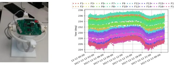
To calibrate the compass a plastic gimbal, shown in Fig. 3 (left), has been designed in order to determine hard/soft iron calibration parameters of the naked board. Following this procedure an accuracy of <3.5 degrees during the DOMs operation in rotation angle has been achieved (Fig. 3, right).
References
1. Adrian Martinez S. et al., Journal of instrumentation 7, T08002 (2012) 2. Adrian Martinez S. et al., Eur. Phys. J. C76, 68 (2016)
3. Adrian Martinez S. et al., Eur. Phys. J. C76, 1 (2016) 4. Adrian Martinez S. et al., Journal of Physics G, 43 (2016) 5. Caruso F. at al., Plos One 10, e0144503 (2015)
6. Sciacca V. et al., Plos One 10, e0141838 (2015) 7. Caruso F. at al., Scientific Reports 7, 4321 (2017) 8. Viola S. et al., Marine Pollution Bulletin 121, 97 (2017)
9. EU Marine Strategy Directive, http://ec.europa.eu/environment/marine/eu-coast-and-marine-policy/marine-strategy-framework-directive/index_en.htm).