R E S E A R C H
Open Access
Interference coordination of heterogeneous
LTE systems using remote radio heads
Jaewon Kim, Donghyun Lee and Wonjin Sung
*Abstract
In this paper, we present an operational strategy to mitigate co-channel interference (CCI) by using geographically distributed remote radio heads (RRHs). The inter-node CCI becomes a dominant performance degradation factor for heterogeneous network (HetNet) systems. Recently, there are emerging attempts in Third Generation Partnership Project to adopt advanced techniques to Long Term Evolution Advanced systems to mitigate CCI problems for HetNet systems, namely, the coordinated multipoint transmission (CoMP). However, the CoMP scheme cannot control the CCI generated from outside coordination boundaries. To resolve this problem, we propose a partial activation strategy by using RRHs deployed near cell edge which results in moving coverage boundary effects. Based on Monte Carlo system level simulations, performance of the conventional strategies and the presented strategy is evaluated. Simulation results show that the proposed scheme outperforms the enhanced inter-cell interference coordination and CoMP schemes especially for users located near cell edge areas.
Keywords: Heterogeneous network, Remote radio head, Coordinated multipoint transmission, Enhanced inter-cell interference coordination, LTE-Advanced
1 Introduction
Limited capacity and coverage holes have been considered as major problems of conventional mobile cellular wire-less systems which only consist of homogeneous macro base stations (BSs) [1]. To solve the problems, the con-ventional systems have been evolved to heterogeneous network (HetNet) systems for which different types of transmission nodes are newly deployed within a cover-age area of the macro BS. The limited capacity can be efficiently increased by letting wireless resources of the macro BS be spatially reused in newly created cover-age areas of the transmission nodes [2]. Moreover, by installing the nodes at the coverage holes of macro BSs, an outage probability of user equipments (UEs) decreases significantly [3].
Different types of transmission nodes have been imple-mented in current systems in forms of pico or femto BSs, relays, and remote radio heads (RRHs) [4]. In gen-eral, pico BSs are deployed by mobile service providers
*Correspondence: [email protected]
Department of Electronic Engineering, Sogang University, Seoul, 121-742, Korea
with smaller coverage areas and transmission power com-pared to macro BSs. On the other hand, femto BSs are installed by users in their private indoor places, and their corresponding coverage areas are much smaller than those of pico and macro BSs. While pico and femto BSs create their own coverage areas, relay nodes are com-monly used to extend the coverage area of macro BSs. RRHs are geographically distributed RF units of a trans-mission node which are connected to their own control units via optical fiber backhaul with nearly ideal condi-tions.
Performance gains of HetNet systems mainly come from two aspects, i.e., decreasing the outage probabil-ity and increasing the system capacprobabil-ity. However, newly installed HetNet transmission nodes may also increase the amount of co-channel interference (CCI) [5]. In the Long Term Evolution Advanced (LTE-Advanced) system, the inter-cell interference coordination (ICIC) and the enhanced ICIC (eICIC) schemes are adopted to miti-gate CCI between transmission nodes [6]. The schemes prohibit undesirable scenarios such that adjacent nodes allocate the same time and frequency resources with full radiation power to UEs located near coverage boundaries.
Thus, these schemes utilize static or semi-static coordi-nation among transmission nodes through X2 interface backhaul for the management of time, frequency, and power resources.
The coordinated multipoint transmission (CoMP) is a promising technique for inter-cell CCI mitigation, which has been included in Third Generation Partnership Project (3GPP) Release 11 specifications [5,6]. Currently, two types of CoMP schemes are considered which are known as the coordinated scheduling/coordinated beam-forming scheme and the joint processing (JP) scheme. For JP, multiple transmission nodes act as a single trans-mitter with geographically distributed antennas for which scheduling information, transmission data, and the chan-nel state information (CSI) are fully exchanged through the backhaul network. Compared to eICIC, CoMP is a far more direct and dynamic solution to reduce CCI.
However, conventional methods cannot be a com-plete solution for interference problem in HetNets. Since some part of radio resources or the transmission power should be reserved for interference mitigation, there exists inevitable performance loss in spectral efficiency in the cases of ICIC and eICIC. For CoMP, performance is largely dependent on capabilities of the backhaul network, which can be a serious bottleneck in obtaining the desired gain [7]. Moreover, CCI problems still exist for the UEs located at coverage boundaries of a cluster of transmission nodes participating in the CoMP [8,9].
In this paper, we propose an interference mitigation strategy using geographically distributed RRHs in HetNet systems. Within a cell, a macro BS and RRHs share the same cell identification (CID) and participate in CoMP to mitigate intra-cell interference. We introduce virtual cell coverage which is the union of two time-varying cov-erage areas. By means of designing the virtual covcov-erage area to be larger than the area where scheduling candi-date UEs are located, our proposal also efficiently miti-gates inter-cell interference from the transmission nodes with different CIDs. Performance of the conventional and presented strategies is evaluated by Monte Carlo system level simulations to demonstrate the effectiveness of the proposal.
This paper is organized as follows. In Section 2, the system model is presented which consists of 57 cells and 19 cell groups. We consider HetNet systems where the macro BSs and the RRHs are referred to as dif-ferent types of transmission nodes. Section 3 presents conventional interference management methods includ-ing eICIC and CoMP. The proposed interference man-agement method in HetNet is described in Section 4. Performance of the presented strategy is evaluated and analyzed in Section 5 based on the numerical results using Monte Carlo simulations. Concluding remarks are given in Section 6.
For notational simplicity, we letX=xi,j
i∈A,j∈Bdenote
the matrix generated by column-wise stacking for alliin Aand row-wise stacking for alljinB. Expressionsxi,j
i∈A
andxi,j
j∈Brespectively denote column-wise stacking and
row-wise stacking.
2 System model
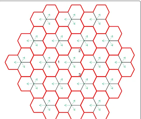
We consider the cellular system shown in Figure 1 which includes a total of 57 cells, where eachcellis the hexago-nal sector coverage area as defined in [10]aand is covered by the macro BS with multiple antenna elements having vertical and horizontal beam patterns. The dashed arrow indicates the center of the horizontal beam pattern for each macro BS. Acell groupis the set of three adjacent cells surrounded by red lines in Figure 1. Macro BSs are co-located at the center of each cell group.
For homogeneous network systems, macro BSs are the only type of transmission node. On the other hand, RRHs are another type of transmission nodes for HetNet sys-tems. The two types of transmission nodes are differen-tiated by various physical parameters including transmit power, antenna height, and antenna beam patterns. The backhaul network within a cell between the RRHs and the macro BS is connected via optical fibers which are assumed to exhibit nearly ideal conditions of zero delay and infinite bandwidth. Hence, in terms of the capability to share information through the backhaul network, geo-graphically distributed transmission nodes can participate in coordination of transmissions and scheduling with no penalty in performance.
Let Mi indicate the number of antennas and Pi
indi-cate the maximum transmit power of theith transmission
1
2
3
node. Let us consider thekth UE with single antenna in the nth cell. Then, the received signal of the UE can be represented as
tively represent the short-term CSI vector and the trans-mit signal vector from theith node. The elements in the short-term CSI vector follow the independent and identi-cally distributed (i.i.d.) complex normal distributions with zero mean and unit variance. The additive white Gaus-sian noise is denoted byzkwhose elements also follow the
i.i.d. complex normal distributions with zero mean andσ02 variance.
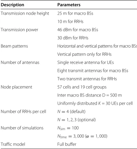
The long-term CSI of the link from the ith node to the kth UE is denoted by sk,i which includes the effects of path loss, shadowing, and antenna beam pat-terns. For simulations in Section 5, the urban macro and the urban micro models are respectively applied to the channels of the macro BSs and the RRHs, as specified in [11]. Both the horizontal and verti-cal antenna beam patterns are applied to the links of macro BS, and the vertical antenna beam pattern is used for the RRHs with omni-directional antennas. Param-eters for antenna beam patterns are per 3GPP Case 1 (Table A.2.1.1-2 in [12]). Specific parameters regard-ing the system and signal models are summarized in Table 1.
Table 1 Simulation parameters
Description Parameters
Transmission node height 25 m for macro BSs
10 m for RRHs
Transmission power 46 dBm for macro BSs
30 dBm for RRHs
Beam patterns Horizontal and vertical patterns for macro BSs
Vertical pattern only for RRHs
Number of antennas Single receive antenna for UEs
Eight transmit antennas for macro BSs
Two transmit antennas for RRHs
Node placement 57 cells and 19 cell groups
Inter macro BS distance D = 500 m
Uniformly distributedK= 30 UEs per cell
Number of RRHs per cell N=4 (default)
N=1, 2, 3 (optional)
Number of simulations Nsim=100
Ntime=3, 000 (α=1, 000)
Traffic model Full buffer
A scheduling region is defined as the area where scheduling candidate UEs are located. A group of trans-mission nodes sharing the same CID within a cell has its own scheduling region, and the corresponding scheduling is made independently to the other regions. Among the UEs within a scheduling region, up toL = 8 UEs can be selected for the multiuser multiple-input multiple-output (MU-MIMO).
3 Conventional interference management
methods (in HetNet)
3.1 eICIC
Typically, a UE chooses its serving node to be the one with the strongest received power. Due to the large difference in transmit power of a macro BS and RRHs, the coverage of RRHs is much smaller than that of a macro BS [13]. In this regard, a significantly smaller number of UEs select the RRHs as their own serving nodes, which yields an imbalance in traffic load between the two types of trans-mission nodes. For traffic load balancing, LTE-Advanced systems adopt cell range expansion (CRE) to low-power transmission nodes by increasing preference values in the process of serving node selection.
Upon applying CRE, however, some UEs may choose RRHs as their serving nodes even though channel gains of RRHs are smaller than channel gains of macro BSs. These UEs suffer from strong interference from macro BSs, and their channel conditions are degraded. The eICIC reduces the interference from macro BSs to the UEs served by RRHs [4,14]. Through the power control of the macro BSs, their transmission is suspended in the designated time duration. In LTE-Advanced specifications, this duration is called the almost blank subframe (ABS).
In performance evaluations of eICIC, we assume that the macro BSs and the RRHs are independent sion nodes with different CIDs. Therefore, each transmis-sion node has its own scheduling region which is identical to the coverage area of the transmission node. To mitigate the inter-node interference, transmission of the macro BS is periodically muted by using the ABS in a synchronous manner. The time duration of the ABS over the entire subframes is controlled by the activation ratioτ. During the ABS, the transmission of control, data, and reference signal from the macro BS is completely eliminated.
For τ portion of entire subframes, the transmission signal of theith node is given by
xi=
k∈Si
wi,k√qkdk (2)
for alli’s within a cell wherewi,k denotes a beamforming
vector for the kth UE and Si is an index set of
for the kth UE is represented bydk, and its power
con-trol scalar is written as qk. Defining the concatenated
channel matrix from theith node to the scheduled UEs asHi = Pisk,iHk,i
k∈Si
, the corresponding zero-forcing
beamforming matrixWn,i=
which cancels out the CCI generated only within the cov-erage area of theith transmission node. To limit the trans-mit power of theith node underPi, which is called the
per-node power constraint, the power allocation variable is set to
qk = |Si|−1wi,k−2 (4)
which guaranteesExi2=1. For the ABS, the
transmis-sion signal is given byxi=0 for the indexiassigned to the
macro BS, while the transmission signals from the RRHs exhibit the same format as the one in Equation 2.
3.2 CoMP
For CoMP, we consider the case of all transmission nodes within a cell, one macro BS and N RRHs, participating in joint transmission. Let us define An as the index set
of transmission nodes within the nth cell. By letting all the nodes in An share the same CID, the RRHs act as
geographically distributed antennas of the macro BS. The coverage area of the set is defined as a single schedul-ing region, and coordination in transmittschedul-ing signals and scheduling UEs is constrained among the transmission nodes within a set. Thus, up toLUEs can be scheduled for the MU-MIMO transmission over the entire cell.
LetSnbe the set of scheduled UEs by thenth cell, which
is also assumed to be given. Then, the transmit signals from the transmission nodes within the cell can be written as
respectively as the concatenated beamforming and channel matrices from the transmis-sion nodes inAnto the scheduled UEs inSn. To eliminate
the CCI among the transmission nodes, the concatenated beamforming matrix is determined by
Wn=HHn
HnHHn −1
. (6)
To satisfy the per-node power constraints, we let the power allocation variable be
qk =
1 μni∈Anwi,k
2 (7)
where the normalization value is given by μn =
maxi∈An
[15]. This solution
guaran-tees that at least one transmission node inAncan satisfy
the per-node constraint with equality and nullifies the intra-cell CCI.
4 Proposed interference management method (in
HetNet)
Unlike conventional eICIC, transmission from RRHs is periodically deactivated, whereas transmission from macro BSs is always being activated. For τ portion of the entire subframes, all transmission nodes in An
participate in CoMP joint transmission to mitigate the intra-cell CCI. In that time period, the transmission signal is generated as the form in Equation 5. For the remaining 1 − τ portion of subframes, the trans-mission from the RRHs is muted, and only the sig-nal from the macro BS is transmitted as given by Equation 2.
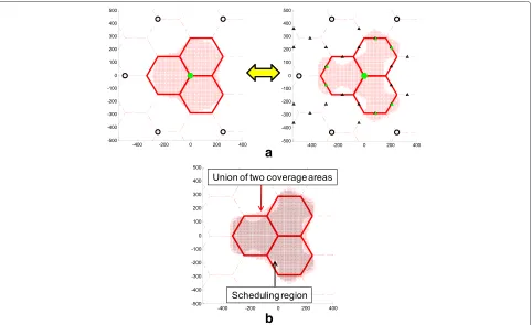
Due to the periodic activation of RRHs, the coverage area for the setAnchanges in time. When the RRHs are
deactivated, the corresponding coverage area is shown in the left-hand side of Figure 2a which is identical to the case of homogeneous network systems. On the other hand, when the RRHs are activated, the corresponding coverage area changes as indicated in the right-hand side of Figure 2a. In this case, the coverage area is identical to the conventional CoMP case. Since we assume that the entire network is synchronized in time, the variations in the coverage area of the setAnare identical for alln.
We propose a concept of virtual coverage area of the set Anwhich is a union of the two coverage areas. Since the
virtual coverage area is the union of two different shapes, it becomes larger than individual areas. For CoMP trans-missions, all transmission nodes in An share the same
CID. To determine the scheduling region of the proposed scheme, a UE measures two signal-to-interference plus noise ratio (SINR) values,γ1,nandγ2,n, for eachAnwhich
correspond to the cases wherein the RRHs are activated and deactivated, respectively. Based on the two values, the UE computes two spectral efficiency values, η1,n = τlog2(1+γ1,n)andη2,n =(1−τ )log2(1+γ2,n). The UE
selects the larger spectral efficiency value as the expected rate of set An. For all sets in the system, the serving set
a
b
Figure 2Moving boundary effects.(a) Alternating cell coverage areas, (b) extended coverage areas larger than the corresponding scheduling region.
the UEs choosing setAn as their serving set become the
scheduling candidate UEs for the set, and the correspond-ing schedulcorrespond-ing region is the areas where the schedulcorrespond-ing candidate UEs are located, as shown in Figure 2b.
The proposed scheme with dynamically activated RRHs results in moving boundaries of the cell coverage area. The moving boundary effect can help prevent the case wherein a certain UE is located at the edge of the cell during the whole transmission time. Therefore, the pro-posed scheme can mitigate inter-cell CCI by letting no scheduling candidate UE be at the boundary of the virtual cell coverage area.
5 Performance evaluations
The UEs scheduled by macro cells, numbered 1, 2, and 3 in Figure 1, are considered for performance evaluations. Along with the SINR, the UE throughput is adopted as a major performance metric [11]. The UE throughput value is also utilized to determine individual UE weight values for proportional fairness. Greedy sequential UE schedul-ing is independently conducted within the cooperation area under the weighted sum-rate maximization criterion [16].
Coverage probability is defined as the probability that a UE has a larger SINR value than the given threshold value.
In Figure 3, the coverage probability is presented with respect to the number of RRHs per cell. This figure shows that the overall coverage probability improved. In particu-lar, the low-tier UE performance is significantly enhanced according to the increase of the number of RRHs. This shows that the SINR gain of the cell boundary can be
Figure 4Comparison of cooperation strategies.WhereN=4 RRHs are positioned on the cell boundary of each macro BS using activation ratioτ=0.7. (a) Performance in SINR, (b) performance in UE throughput.
achieved by signal transmission from RRHs to UEs located in cell boundary areas.
In Figure 4, the performance of the proposed scheme is compared to the conventional schemes in terms of SINR and UE throughput. The conventional eICIC scheme shows better UE throughput performance (about 122.4% on average) than the homogeneous system with the macro BS only. Through the comparison of conventional eICIC and CoMP, it is observed that the effect of intra-cell interference cancellation by the ZF produces performance gain. A difference in performance between the proposed scheme and the conventional CoMP scheme results from the decrease of inter-cell interference due to moving boundary effects. The proposed scheme demonstrates improved performance over conventional CoMP, includ-ing 110% UE throughput gain for low 5% UEs in terms of throughput.
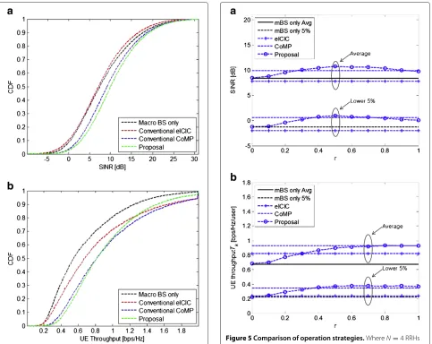
Figure 5Comparison of operation strategies.WhereN=4 RRHs are positioned on a cell boundary of each macro BS. (a) Performance in SINR, (b) performance in UE throughput.
In Figure 5, the proposed scheme and the conventional schemes including the macro BS only, eICIC, and CoMP are compared with respect to activation ratioτ. In the case ofτ = 0, the proposed scheme shows the same perfor-mance with that of the macro BS-only scheme because all RRHs are deactivated. The proposed scheme, on the other hand, exhibits the same performance with that of the conventional CoMP scheme whenτ = 1 because all RRHs are activated. Through the selection of a proper τ value, we can maximize both the SINR performance and UE throughput performance. When the lower 5% UE throughput is chosen as the main performance metric, the optimum value ofτ = 0.7 produces nearly 280% UE throughput gain over the homogeneous system.
a
b
c
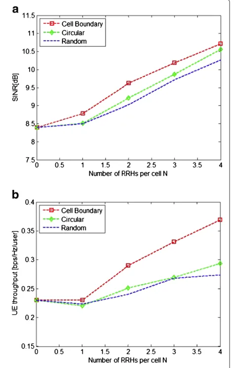
Figure 6Different scenarios of RRH deployment forN=2.(a) Random positioning, (b) circular positioning, (c) cell boundary positioning.
cell according to a uniform distribution. Since UEs are also randomly located according to a uniform distribution, the average distance between a UE and a transmission node becomes smaller asNincreases. ForNC = 3N, RRHs on
the same circle, their positions are uniformly determined as shown in Figure 6b where the distance of two adjacent RRHs is set to d1. Distance d1 monotonically increases
with respect to the radiusRof the circles. On the other hand, let us defined2as the minimum distance between
RRHs located on different circles. Since the inter-macro BS distance is fixed, distanced2monotonically decreases
with respect to the radiusR. Therefore, the optimal value of R can be obtained by letting d1 = d2. We can also
consider RRHs located at the boundary of cell groups, as shown in Figure 6c, where the amount of inter-cell CCI is maximum. Since adjacent cell groups share common cell boundaries, positions of RRHs are divided into three dif-ferent cell groups to prevent duplicated RRH positions.
For a given cell group boundary,NCRRHs which are
affil-iated to three different adjacent cell groups are deployed. As in the circular positioning scheme, potential loca-tions of RRHs are determined to maximize the minimum distance between two adjacent RRHs.
In Figure 7, the average SINR and the lower 5% UE throughput performance of different positioning scenar-ios are presented for the increasing value ofN. The pro-posed scheme expands the virtual cell coverage through the moving cell boundary effect utilizing partial activation of RRHs in a time division fashion. In this way, we can ensure that the scenario wherein RRHs are located at the cell boundary provides enhanced performance over other scenarios.
6 Conclusions
In this paper, we presented an interference mitigation strategy to mitigate the intra-cell and inter-cell CCI prob-lems via utilization of RRHs combined with CoMP. Moti-vated by the conventional eICIC and CoMP schemes, the proposed scheme not only utilizes CoMP transmission to eliminate intra-cell CCI but also partially activates cell-edge-located RRHs to control inter-cell CCI. In particular, we proposed the concept of moving boundary and vir-tual cell coverage, which can be efficiently adopted in the current specification of LTE-Advanced systems. Simula-tion results confirm the performance improvement of the proposal, and the reduction of inter-cell CCI gives a sig-nificant performance gain especially for the low-tier UEs near cell boundary areas.
Endnote
aUnlike 3GPP where cell is defined as a coverage area
of any transmission node, we only use the term ‘cell’ as a hexagonal area of macro BS. Therefore, interference between the macro BS and the RRHs refers to intra-cell interference or inter-node interference.
Competing interests
The authors declare that they have no competing interests.
Acknowledgements
This work was supported by a grant from the National Research Foundation of Korea (NRF) funded by the Korean government (MEST) (no. 2011-0016146).
Received: 3 June 2012 Accepted: 3 April 2013 Published: 26 April 2013
References
1. M Rahman, H Yanikomeroglu, Enhancing cell-edge performance: a downlink dynamic interference avoidance scheme with inter-cell coordination. IEEE Trans. Wireless Commun.9(4), 1414–1425 (2010) 2. D Astely, E Dahlman, A Furuskar, Y Jading, M Lindstrom, S Parkvall, LTE: the
evolution of mobile broadband. IEEE Commun. Mag.47(4), 44–51 (2009) 3. A Damnjanovic, J Montojo, Y Wei, T Ji, T Luo, M Vajapeyam, T Yoo, O Song,
D Malladi, A survey on 3GPP heterogeneous networks. IEEE Wireless Commun. Mag.18(3), 10–21 (2011)
4. D Lopez-Perez, I Guvenc, G de la Roche, M Kountouris, T Quek, J Zhang, Enhanced intercell interference coordination challenges in
heterogeneous networks. IEEE Wireless Commun. Mag.18(3), 22–30 (2011)
5. M Sawahashi, Y Kishiyama, A Morimoto, D Nishikawa, M Tanno, Coordinated multipoint transmission/reception techniques for LTE-advanced [Coordinated and distributed MIMO]. IEEE Wireless Commun. Mag.17(3), 26–34 (2010)
6. R Irmer, H Droste, P Marsch, M Grieger, G Fettweis, S Brueck, HP Mayer, L Thiele, V Jungnickel, Coordinated multipoint: concepts, performance, and field trial results. IEEE Commun. Mag.49(2), 102–111 (2011)
7. 3rd Generation Partnership Project, TSG RAN: (E-UTRA). 3GPP TR 36.819 version 11.1.0 Coordinated multi-point operation for LTE physical layer aspects (Release 11) (2011). http://www.3gpp.org/ftp/Specs/html-info/ 36819.htm
8. P Marsch, G Fettweis, inIEEE International Conference on Communications
(ICC). Static clustering for cooperative multi-point (CoMP) in mobile
communications (Kyoto, 5–9 June 2011)
9. J Zhang, R Chen, J Andrews, A Ghosh, R Heath, Networked MIMO with clustered linear precoding. IEEE Trans. Wireless Commun.8(4), 1910–1921 (2009)
10. P Marsch, G Fettweis,Coordinated Multi-Point in Mobile Communications
From Theory to Practice. (Cambridge University Press, Cambridge, 2011)
11. I T U, Guidelines for evaluation of radio technologies for IMT-Advanced. TS ITU-R, M.2135 (2008). http://itu.int/publ/R-REP-M.2135-2008/en 12. PartnershipProject 3rd Generation, TSG RAN: (E-UTRA): 3GPP TR 36.814
version 9.0.0 Evolved universal terrestrial radio access (E-UTRA). Further advancements for E-UTRA physical layer aspects (Release 11) (2010) 13. M Li, J Zhou, L Liu, X She, L Chen, inIEEE International Conference on
Communications Workshops (ICC Workshops). Secondary serving cell
selection for heterogeneous network with RRH deployment (Kyoto, 5–9 June 2011)
14. Y Hong, N Lee, B Clerckx, inIEEE GLOBECOM Workshops (GC Wkshps). System level performance evaluation of inter-cell interference coordination schemes for heterogeneous networks in LTE-A system (Miami, 6)
15. H Zhang, H Dai, Cochannel interference mitigation and cooperative processing in downlink multicell multiuser MIMO networks. EURASIP J. Wirel. Commun. Netw.2004(2), 222–235 (2004)
16. C Guthy, W Utschick, R Hunger, M Joham, Efficient weighted sum rate maximization with linear precoding. IEEE Trans. Signal Process.58(4) (2010)
doi:10.1186/1687-6180-2013-90
Cite this article as:Kimet al.:Interference coordination of heterogeneous LTE systems using remote radio heads.EURASIP Journal on Advances in Signal Processing20132013:90.
Submit your manuscript to a
journal and benefi t from:
7Convenient online submission
7 Rigorous peer review
7Immediate publication on acceptance
7 Open access: articles freely available online
7High visibility within the fi eld
7 Retaining the copyright to your article