98 | P a g e
REVIEW OF FINITE ELEMENT ANALYSIS OF
ROLLER CONVEYOR FOR MATERIAL HANDLING
SYSTEM
Mr. S.M. Math
1, Prof
.S.B .Naik
21
Student of ME-II (Mechanical-Design), Walchand Institute Of Technology,Solapur, (India)
2
Asst.Professor in Mechanical Deptt, Walchand Institute Of Technology,Solapur, (India)
ABSTRACT
Material handling plays an important role in the modern industries now a days. Almost every item of physical
commerce is transported on a conveyor or lift truck or other type of material handling equipment in manufacturing
plants, warehouses, and retail stores. The current work focuses on the weight reduction of the gravity roller by
redesigning and save considerable amount of material. In this paper the comparison of the design calculation for the
gravity roller before and after optimization are detailed.
Keywords: Gravity Roller, Conveyor, Optimisation
I INTRODUCTION
Today’s world is of automation and modernization in the manufacturing techniques. Material Handling is the part of
this modern technique which are of importance in any of the industry. Material handling plays an important role in
manufacturing and logistics. Almost every item of physical commerce is transported on a conveyor or lift truck or
other type of material handling equipment in manufacturing plants, warehouses, and retail stores. The operators use
material handling equipment to transport various goods in a variety of industrial settings including moving
construction materials around building sites or moving goods onto ships. A conveyor system is a common piece of
mechanical handling equipment that moves materials from one location to another. Conveyors are especially useful
in applications involving the transportation of heavy or bulky materials. In today’s radically changing industrial
markets, there is a need to implement a new manufacturing strategy, a new system operational concept and a new
system control software and hardware development concept, that can be applied to the design of a new generation of
99 | P a g e
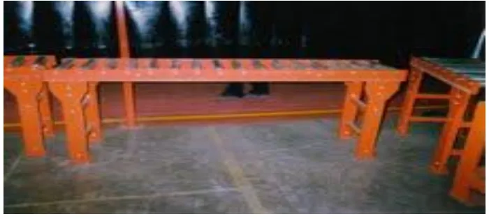
II PROBLEM DEFINITION
The aim of this work is to redesign existing gravity roller conveyor system by designing the critical parts (Roller,
Shaft, Bearing & Frame), to minimize the overall weight of the assembly and to save considerable amount of
material. Also system needs to be examined for ‘load case’ of sudden release of the component over the conveyor
system. The existing conveyor system is shown in the figure below.
Figure. 1.2 Roller Conveyor System (Existing Case)
Gravity roller Conveyor has to convey 350 kg load, 30 inch above ground and inclined at 4 degree. Figure. 1.3
100 | P a g e
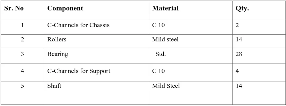
Table 1.1 Components of the Conveyor system
Sr. No
Component
Material
Qty.
1
C-Channels for Chassis
C 10
2
2
Rollers
Mild steel
14
3
Bearing
Std.
28
4
C-Channels for Support
C 10
4
5
Shaft
Mild Steel
14
3.1 DESIGN CALCULATIONS FOR EXISTING CONVEYOR
The design calculations for the existing system was carried out as follows
3.1.1 Design of Roller
Roller is made of MS.Material properties of MS are as follows,
Young’s modulus of elasticity E = 2.0×10⁵ MPa,
Material density ρ= 7850 Kg/m3,
Yield stress = 250 MPa
Considering uniformly distributed load & factor of safety FS = 1.5
Allowable Stress (σall) = Syt / Fs =250/1.5=166.67 MPa For 40 mm Diameter
Maximum Stress Calculation for given condition -
W= 12 kg (Load act on 4 rollers at a time)
D1= Outer diameter of roller = 40 mm
D2 = Inner diameter of roller = 40-(2x2) =36 mm
w = Width of roller = 500 mm
y = Distance from neutral axis = 30/2 = 15mm
Considering uniformly distributed load, fixed at both ends.
Maximum Moment (Mmax) = = 14715Nmm
101 | P a g e
Maximum bending stress σb = =5.1101N/mm2Checking Factor of Safety for design-
Fs = = 32.61
As Calculated Fs is greater than assumed Fs, Selected Material can be considered as safe.
Maximum Deflection (ymax) = = 4.4358x10⁻⁹mm
As compared to length 500 mm deflection of = 4.4358x10⁻⁹mm is very negligible. Hence selected roller can be
considered as safe.
Similar5 calculations were carried out for the 35 mm diameter and 30 mm diameter where the factor of safety
obtained are 16.38 and 11.73 respectively
As compared to length 500 mm deflection of 1.2325X10⁻⁸ mm is very negligible. Hence selected roller can be
considered as safe.
Weight of Rollers - = cross-section area×width × mass density× number of rollers=103.57 Kg
3.1.2 Design of Shaft
Shaft is made of MS.Material properties of MS are as follows,
Young’s modulus of elasticity E = 2.0×10⁵ MPa,
Material density ρ= 7850 Kg/m3,
Yield stress = 250 MPa
Considering uniformly distributed load & factor of safety FS = 1.5
Allowable Stress (σall) = Syt / Fs =250/1.5=166.67 MPa
Maximum Stress Calculation for given condition-
Maximum Moment (Mmax) = 13.96 Nm
Moment of Inertia I = П (D4)/64 =7.8540×10⁻⁹ m4
Maximum bending stress σb = = 17.78 MPa
Checking Factor of Safety for design-
Fs = =9.374
As Calculated Fs is greater than assumed Fs, Selected Material can be considered as safe.
102 | P a g e
The B.M.at any section distance ‘x’ from pt.A is given by,EI× = 465.47× x|-465.47(x-0.03)|-465.47(x-0.53)
Integrating the above eq.n we get,
EI× = 465.47× x2/2+C1|-465.47(x-0.03)2/2|-465.47(x-0.53)2/2
=
232.73× x2+C1 |-232.73 (x-0.03) 2
|-232.73 (x-0.53)2
EI×y = 77.57× x3-3.696× x + |-77.57 (x-0.03)3|-77.57 (x-0.53)3………(2)
To find deflection at point ‘D’,put x=0.53m in eq.n 2,
Take E=2.1×10⁵ MPa & I=7.8540×10⁻⁹ m4
YD= -0.65 mm. (downward)
Deflection is remains same in between point C & D because there is no any other load acted.
Hence Maximum Deflection (ymax):0.65 mm
As compared to length 560 mm deflection of 0.65mm is very negligible. Hence selected shaft can be considered as
safe.
Weight of Shafts = cross-section area× width × mass density× number of shafts = 19.33 Kg
3.1.3 Design of c-channel for Chassis
C-channel for chassis is made of rolled steel C-10.Young’s modulus of elasticity E = 2.0×10⁵ MPa,
Material density ρ= 7850 Kg/m3,
Yield stress = 275 MPa
Maximum Stress Calculation for given condition -
Maximum bending moment (Mmax) = 1319.63 Nm
Maximum bending stress σb= =35.34 MPa
103 | P a g e
Fs = = 5.18
As Calculated Fs is greater than assumed Fs, Selected Material can be considered as safe.
Maximum Deflection (ymax)-
ymax = =1.357×10⁻³ m
As compared to length 2200 mm deflection of 1.37mm is very negligible. Hence selected channel can be considered
as safe.
Weight of C-frame -
= cross-section area×length of frame× mass density = 2×20.15 = 40.30kg
3.1.4 Design of C- Channel for Supports
Maximum bending moment (Mmax) = = 247.03 Nm
Maximum bending stress,
σb = -73.53 MPa
Checking Factor of Safety for design
Fs = = 2.49
As Calculated Fs is greater than assumed Fs, Selected Material can be considered as safe.
Maximum Deflection (ymax) = =0.445 mm
As compared to length 762 mm deflection of 0.445mm is very negligible. Hence selected channel can be considered
as safe.
Table Weight of Optimized Conveyor
Sr. No.
Name of Component
Weight (Kg)
(Approx)
1
C- Channel for Chassis
2
Rollers
47.47
3
Shafts
19.33
4
Bearing
6.982
5
C- Channel for Supports
19.93
104 | P a g e
IV RESULTS BEFORE OPTIMIZATION
From static analysis of existing roller conveyor it is clear that when a static load of 875 N (approx 87.5 Kg = 350
Kg/4) is applied on the roller at the centre. We found that the maximum deflection is 0.0089 mm and maximum
stress is 4.56 MPa.
From analytical design calculation of existing roller conveyor it is clear that when a static load of 875 N (approx
87.5 Kg = 350 Kg/4) is applied on the roller at the centre. We found that the maximum deflection is 0.0016 mm and
maximum stress is 0.717 MPa.
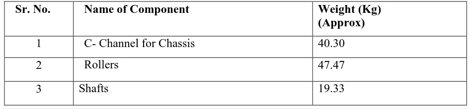
Table 5.1 Total Weight of Existing Conveyor
Sr. No.
Name of Component
Weight (Kg)
(Approx)
1
C- Channel for Chassis
40.30
2
Rollers
103.57
3
Shafts
19.33
4
Bearing
6.982
5
C- Channel for Supports
19.93
6
Total Weight of assembly
190.192
V RESULTS AFTER OPTIMIZATION
From static analysis of optimized roller conveyor it is clear that when a static load of 875 N (approx 87.5 Kg = 350
Kg/4) is applied on the roller at the centre. We found that the maximum deflection is 0.0022 mm and maximum
stress is 8.08 MPa.
From analytical design calculation of existing roller conveyor it is clear that when a static load of 875 N (approx
87.5 Kg = 350 Kg/4) is applied on the roller at the centre. We found that the maximum deflection is 0.0042 mm and
maximum stress is 1.63 MPa.
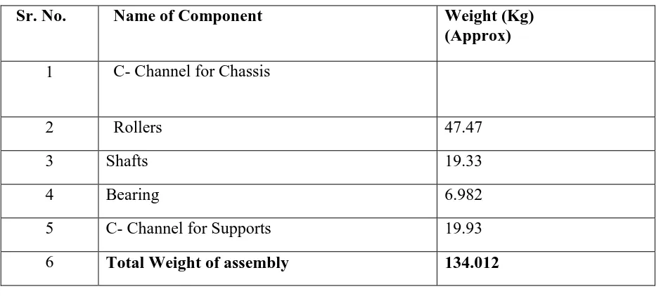
Table Total Weight of Optimized Conveyor
Sr. No.
Name of Component
Weight (Kg)
(Approx)
1
C- Channel for Chassis
40.30
2
Rollers
47.47
105 | P a g e
4
Bearing
6.982
5
C- Channel for Supports
19.93
6
Total Weight of assembly
134.012
5.1
EFFECT OF OPTIMIZED DESIGN COMPARED WITH EXISTING DESIGN-
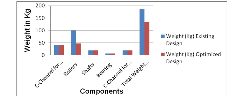
Table Effect Optimized Design
Sr. No.
Name of Component
Existing Design
Weight (Kg)
Optimized Design
Weight (Kg)
1
C- Channel for Chassis
40.30
40.30
2
Rollers
103.57
47.47
3
Shafts
19.33
19.33
4
Bearing
6.982
6.982
5
C- Channel for Supports
19.93
19.93
6
Total Weight of assembly
190.192
134.012
1) From above table we can observe that there is great change in weight of optimized design as compared to
existing design (56.18 Kg weight reduction).
2) Here we can say that change in dimension of Rollers optimizes the weight of entire conveyor system.
106 | P a g e
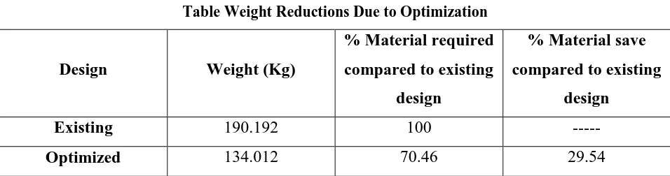
Weight Reduction Due to Optimization:-
Table Weight Reductions Due to Optimization
Design
Weight (Kg)
% Material required
compared to existing
design
% Material save
compared to existing
design
Existing
190.192
100
---
Optimized
134.012
70.46
29.54
As per the standards of Conveyor manufacturing companies’ permissible deformation is 8 mm.
VI CONCLUSION
Existing design calculation shows the factor of safety is very greater than requirement
and there is a scope for weight reduction.
The critical parameter for weight reduction is Outside Diameter of Roller. Though the
values of deflection and stress are more in case of optimized but it is allowable.
29.54 % of weight reduction is achieved due to optimized design.
56.18 Kg of weight reduction is achieved due to optimized design as compared to existing design.
REFERENCES
1. “Survey Of Research In Modeling Conveyor-Based Automated Material Handling Systems In Wafer Fabs” Published by Dima Nazzal ,Ahmed El-Nashar Department of Industrial Engineering and Management Systems,
University of Central Florida.
2. “An Investigation Into Design And Manufacturing Of Mechanical Conveyors Systems For Food Processing” S.H. Masood • B. Abbas • E. Shayan • A. Kara,Int J Adv Manuf Technol (2005) 25: 551–559,DOI
10.1007/s00170-003-1843-3 ,Received: 29 March 2003 / Accepted: 21 June 2003 / Published online: 23 June
2004,Springer-Verlag London Limited 2004
3. “Latest Developments In Belt Conveyor Technology”, M. A. Alspaugh ,Overland Conveyor Co., Inc. Presented at MINExpo 2004 Las Vegas, NV, USA.
4. “The Henderson Coarse Ore Conveying System- A Review Of Commissioning, Start-Up, And Operation”,Kung, Walter, Bulk Material Handling by Belt Conveyor 5, Society for Mining, Metallurgy and Exploration, Inc.,
2004.
107 | P a g e
6. “Modeling Power & Free Conveyor Systems” Dev P. Sathyadev, Sanjay Upendram Eric Grajo, Ali Gunal, OnurUlgen Production Modeling Corporation Dearborn, Michigan 48126.
7. “Availability Modeling Of Powered Roller Conveyor John” R. English University of Arkansas, John Usher University of Louisville G., Don Taylor Virginia Polytechnic Institute and State University Ed Pohl University
of Arkansas.