299 | P a g e
CLIMATE CHANGE: MITIGATION STRATEGYBY
VARIOUS CO
2
SEQUESTRATION METHODS
R. K. Saran
1, Raj Kumar
2, Shashikant Yadav
31
Research Scholar, Department of Civil Engineering, Indian Institute of Technology Bombay,(India)
2
Research Scholar, Dr. SSBUICET, Punjab University, Chandigarh, (India)
3
Research Scholar, Department of Chemical Engg, Indian Institute of Technology Bombay, (India)
ABSTRACT
The ever-growing energy demands worldwide have been satisfied through the use of fossil fuels. The
repercussion of this has been the increase in carbon dioxide concentration in the atmosphere. Given the adverse
effect of high levels of CO2 in the atmosphere, there is a recognized need for strategies to mitigate the effects.
The approach to research in this area includes studies which investigate the capture and safe, permanent
disposal of CO2. In the present study, various technological options have been suggested for the purposes of safe
storage of CO2—for example, geological (e.g., depleted oil and gas reservoirs, oceans, and aquifers), biological
and mineral storage.
I INTRODUCTION
The entire world is grappling with the increase of carbon dioxide in the atmosphere and its adverse
environmental impact. CO2 is the largest contributor by volume to the purported greenhouse gas effect; Methane
(CH4), Nitrous Oxide (N2O) and other halocarbons being the other contributors. It was observed that the
atmospheric CO2 concentration levels started rising significantly shortly after the industrial revolution and has
continued to do so till date. The atmospheric CO2 concentration had increased significantly from 280 ppm in
Pre-Industrial era to 385 ppm in 2008 (Modern era). Notably, it is observed that the atmospheric CO2
concentration shows a steep growth rate of 2 ppm on an average since the turn of the millennium (Brierley and
Kingsford 2009). High atmospheric CO2 concentration causes global climate change leading to devastating
effects on ecosystems and cause calamities such as drought, floods, and cyclones. Moreover, various organisms
are under the threat of extinction due to the changes caused in the ecosystem (Marini 2007). It is observed that
atmospheric CO2 concentration and mean global temperature are directly proportional. Though this does not
necessarily prove a direct cause–effect relationship, it still holds significance as it shows that the rise in
atmospheric CO2 concentration is a contributor to Global Warming. Thus, it is required to devise new strategies
to meet energy demands with techniques that have lower emissions or none (IPCC 2005).There are three notable
strategies for reducing CO2 emissions namely: by using energy efficient technologies with decreased fossil fuel
300 | P a g e
and nuclear and by using Carbon Capture and Storage (CCS) technology. Though the first two solutions have
gained traction over the last few years to reduce CO2 emissions, there is still a conceivable need to manage the
CO2 emissions that take place. Therein lies the need for CCS technology. In CCS technology, CO2 is separated
from the flue gas of a static CO2 source such as a power plant utilizing fossil fuels and subsequently stored for
long–term isolated from the atmosphere (IPCC 2005). The process of CCS occurs in three stages: capture,
transport, and storage. The CO2 is collected from a static emitter, usually a power plant, and is then routed to a
storage site through pipes.
It is found that there are four viable storage sites (also known as carbon sinks) with different characteristics with
respect to their limitations, longevity, and costs involved. These alternatives are classified as mineral, biological,
geological and ocean storage methods. The atmosphere holds roughly 60% of the carbon emissions, the other
40% being retained in ―carbon sinks‖, such as vegetation, bodies of water and rocks. The world's biggest carbon
sink are carbonate rocks which is a form of mineral storage method (Liu and Zhao 2000). The captured CO2
needs to be stored permanently in order to avoid its re–emission back into the atmosphere. It is also found that
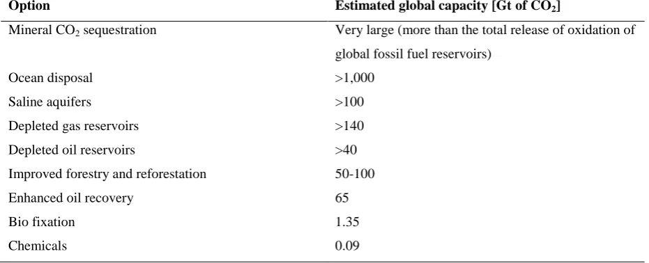
mineral storage has the highest CO2 storage capacity and hence can effectively sequester all existing CO2
emissions as shown in Table 1. Another distinguishing characteristic of mineral storage is that it is safer than
other forms of sequestration such as biological or ocean storage methods, which are plagued by environmental
concerns (Lackner 2002; Huijgen and Comans 2003; Sipilä et al. 2008; Hitch et al. 2010; Sanna et al. 2014).
Table 1:Estimated potential of CO
2storage and utilization options(Huijgen and Comans 2003)
Option Estimated global capacity [Gt of CO2]
Mineral CO2 sequestration Very large (more than the total release of oxidation of
global fossil fuel reservoirs)
Ocean disposal >1,000
Saline aquifers >100
Depleted gas reservoirs >140
Depleted oil reservoirs >40
Improved forestry and reforestation 50-100
Enhanced oil recovery 65
Bio fixation 1.35
Chemicals 0.09
II METHOD OF CO
2SEQUESTRATION
CO2 sequestration through geological, biological, ocean and mineral storage methods are described below.
2.1. Geological Sequestration
Geological sequestration is an underground storage method which is currently implemented for CO2
301 | P a g e
aquifers and salt caverns.
2.1.1. Oil and Gas Reservoirs
The storage of CO2 inside oil and gas reservoirs is found to be the most appealing geological sequestration
method in recent times due to the highest CCS capacity among the geological sequestration methods. It still
suffers from the pitfalls associated with geological sequestration such as high leakage rate and inadequate
capacity compared to other carbon sequestration methods (Park 2005).
Oil and gas reservoirs are further classified into active and depleted reservoirs. Both types are viable for the
sequestration process. There are three factors that affect the CCS efficiency in these sites, namely: presence of
underground water, the distance between the storage site and the emission source and leakage rate. Wet
reservoirs where a large volume of water is present offer little accommodation for CO2 storage in contrast to dry
reservoirs. Gas fields offer maximum storage of CO2, almost equal to that of the original gas quantity due to
negligible presence of water (Holloway 2005). The insertion of CO2 into the oil and gas reservoir increases
pressure on the site which helps boost the potential extraction quantity of oil and/or gas through secondary
recovery. It is estimated that, during this process, when CO2 is injected to recover oil and gas, extracted volume
can be increased by upto 15% in gas recovery and upto 50% in oil recovery in active reservoirs (IEA, 2004).
Enhanced Gas Recovery (EGR) and Enhanced Oil Recovery (EOR) methods thus provide a more economical
solution for CO2 insertion (IEA 2004). While these options appear to be frugal and offset the costs incurred for
CCS, it is sensitive to location (i.e.) the distance between the storage site and the emission source affects the
costs substantially (IEA 2004). It should be ensured that the sum of insertion and transportation expenses must
not exceed the secondary recovery value threshold to keep it viable (Ragnheidardottir 2010). Another issue to
reckon with is the longevity of these storage sites due to the possible leakage caused by impermanence of crust
and other unforeseen conditions (Levi 2005). This requires long–term monitoring to manage potential leakage
given its associated health and safety risks.
2.1.2. Deep Coal Seams
Deep coal seams also provide a viable host for CO2 sequestration with high permanence. There are fractures
within coal seams commonly referred to as ―cleats‖. These pore spaces can host CO2 permanently without
leakage. The storage capacity will vary by region and so a case by case analysis is always important since there
is no real standardization analysis available (IPCC 2005). The recovery of coal–bed methane (CBM) is
dependent on the pressure and temperature in exhausted coal seams. Both pressure and temperature are
enhanced during CO2 injection (Voormeij and Simandl 2004).
2.1.3. Deep Saline Aquifers
302 | P a g e
found in most of the sediment basins. Saline aquifers are reservoirs of water with high salt concentration that is
not fit for human consumption (Voormeij and Simandl 2004). Prior to the development of CO2 sequestration,
saline aquifers were used as storage sites for other forms of hazardous waste. Aquifers, when used as carbon
sinks present only a small portion (approx. 2%) of their available volume for the deposit of CO2. It also suffers
from risk of high leakage rate given the likely occurrence of cap fractures (Voormeij and Simandl 2004). CO2
sequestration in the aquifer is affected by buoyancy, surface area of undissolved CO2 and the differences in
density and viscosity between the injected CO2 and the aquifer water. Buoyancy effect causes CO2 inserted into
an aquifer water to rise and then gradually disperse into a layer underneath the cap of the aquifer (Gale 2004).
The most pronounced process in the initial stages of the reaction is the dissolution of CO2 into the aquifer water
and this rate of dissolution is dictated by the surface area of undissolved CO2 in contact with the aquifer water
(Gunter et al. 1997). Since CO2 separates and moves upward at a faster rate when density and viscosity
differences between CO2 and the aquifer water is higher, it is necessary to insert CO2 under high pressure to
ensure high CO2 density and thus increase CO2 solubility in the aquifer water (Voormeij and Simandl 2004).
2.1.4. Salt Caverns
Salt caverns are another geological storage option that offer high permanence. They are defined as the massive
cavities that remain after extraction of salt by injecting water in an underground salt bed and removing salt in
the form of brine (Voormeij and Simandl 2004). They offer spaces as large as 5x10⁵ m3 in volume available for
CO2 storage (Bachu 2000). Given the impermeability of salt layers, the caps of these spaces would be potent
barriers against leakage (Levi 2005). However, this storage site has two major problems: environmental
concerns with respect to the disposal of brine and high costs (Voormeij and Simandl 2004). Hence, this method
is not widely viewed as a viable option.
2.2. Biological Sequestration
Trees and other vegetation host CO2 during photosynthesis. During photosynthesis, plants absorb CO2 along
with water and convert it into low–carbon compounds, for e.g., cellulose or starch. Biological sequestration by
photosynthesis whether in soil or biomass has a sequestration capacity of approximately 100 Gt of carbon per
year making it a viable option (Park 2005). Another biological option is marine biological sequestration where
CO2 is sequestered in marine plants. The associated costs of biological sequestration are usually very low; for
example, forest planting in developing nations may be as low as 3 to 10 USD per ton of CO2 captured (Paustian
et al. 1998). Biological sequestration poses the risk of less carbon efficient natural ecosystems being supplanted
by monocultures for the purpose of CCS creating an imbalance in the ecosystem. Marine biological
sequestration also has other disadvantages such as insufficient CCS capacity and disruption of the marine food
chain.
303 | P a g e
Ocean sequestration commonly referred to as deep ocean sequestration is the largest CO2 host method having
CCS potential greater than the combined CCS potential of geological and mineral storage methods. A significant
fraction of CO2 is naturally sequestered by the ocean without any effort by exchange of CO2 between
atmosphere and ocean water until chemical equilibrium is established. The equilibrium concentration of CO2
between the atmosphere and the ocean is approximately 1:4. Ocean sequestration however is not permanent as
the dissolution is directly proportional to depth. Therefore, high sequestration permanence and high
sequestration capacity can be achieved simultaneously through deep insertion at depths below 1500 m. Oceans
are estimated to be capable of hosting CO2 for a maximum of 500 years post which the CO2 is re–emitted back
to the atmosphere (Voormeij and Simandl 2004). Currently, it cannot be determined precisely when that occurs.
Until a means of quantifying that time period is created, ocean sequestration remains questionable (Levi 2005).
Ocean sequestration also poses environmental concerns such as climate change and marine chemical changes.
Also leakages can occur by sudden expulsion of stored CO2 during volcanic activity and mantle plumes within
the ocean (Park 2005). CO2 leakage can also occur due to its lower density compared to ocean water which
causes droplets of CO2 to move upward until dissolution occurs and subsequently this CO2–saturated solution
will fan out into the surrounding ocean water. The leakage can be reduced if CO2 sequestration is done at greater
depths as discussed earlier but advanced technology is required for deep insertion which increases the
costs(Voormeij and Simandl 2004).
2.3.1. Storing CO2 as Clathrates
Another method of ocean sequestration is to spawn lakes of CO2 on the ocean floor at depths below 3000 m.
Depths of this magnitude create high water pressure and provide low temperature due to limited supply of
sunlight which converts CO2 into its liquid state that has a higher density than ocean water. Reaction between
CO2 and the ocean water will create a clathrate, which is a cage matrix comprised of roughly six H2O molecules
for every CO2 molecule (Sloan 2003). Pure CO2–hydrate has a higher density than ocean water and will produce
a falling plume which will rest on the ocean floor (Brewer et al. 2000). This technique would cause the
agglomeration of sequestered CO2 in the deep sea trenches (Voormeij and Simandl 2004). However, CO2–
hydratesare unstable and will dissolve when CO2 concentration levels in ocean water return to normal levels
subsequently leading to CO2 leakage. This poses environmental risks causing changes to the ocean chemistry
eventually causing adverse impacts on the marine ecosystem.
2.4. Mineral sequestration
Mineral sequestration is another viable carbon sequestration method which offers high-capacity storage
(>10,000 Gtof CO2), which means the worldwide supply of minerals can likely sequester all future
emissions(Sanna et al. 2014). The interest in mineral sequestration is most pronounced in regions where
underground sequestration is impossible or decidedly unfeasible(Sipilä et al. 2008). There are two significant
advantages mineral sequestration has in comparison to other options (e.g., geological): the safety and
304 | P a g e
abundance of viable feedstock. This post–sequestration monitoring is unnecessary(Liu and Zhao 2000).
Table 2: Feedstock for mineral carbonation
Feedstock Examples
Natural minerals Wollastonite, olivine, serpentine, feldspar, basalt, brucite, pyroxene, forsterite,
dunite
Industrial wastes Steel slag, cement waste, fly ash, MSWI ash, paper mill waste, oil shale ash,
mine tailing
The most abundant minerals utilized in carbonation reactions are those rich in calcium and magnesium such as
olivine and wollastonite(Huijgen and Comans 2003). High concentrations of magnesium and calcium–based
compounds in many industrial by–products and residues are also candidates for sequestration—for example,
iron and steel slags, different types of process ashes, and cement–based waste materials as listed in Table
2(Eloneva et al. 2009). Though the total amount of residues and by–products is smaller than that of naturally–
sourced materials, they are easy to acquire, continuously spawned, and are often more conducive to reaction
than natural materials. Also, the products (e.g., pure CaCO3) of the process may have industrial
applications(Motz and Geiseler 2001; Teir et al. 2007).
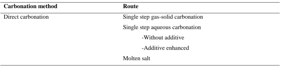
2.4.1.Mineral carbonation route
Various process routes have been studied in the literature with the majority of these routes can be classified into
two categories: direct carbonation or indirect carbonation routes. Direct carbonation route utilizes a single step
carbonation process in which both the dissolution of minerals and carbonation reaction occurs in a single
reactor.A problem with this approach is that its reaction rates under atmospheric conditions occur at a speed not
considered viable for industry; therefore, research has focused on the acceleration of this process(O’Connor et
al. 2002). Indirect carbonation utilizes several additive chemicals such as HCl, H2SO4 and HNO3 to accelerate
the carbonation process(Baciocchi et al. 2010; Bao et al. 2010). Indirect carbonation route occurs in two steps.
In the first step, extraction of reactive minerals occurred at low pH and then carbonation at a higher pH in a
separate reactor. A list of different carbonation routes is given in Table 3.
Table 3: Different carbon sequestration routes
Carbonation method Route
Direct carbonation Single step gas-solid carbonation
Single step aqueous carbonation
-Without additive
-Additive enhanced
305 | P a g e
Indirect carbonation Two step gas-solid carbonation
HNO3 acid
CH3COOH acid
HCl acid
NH4-salt extraction
Precipitated CaCO3
pH swing
Three steps- caustic soda
Molten salt
Brine solution
Duel alkali
The process can also be substantially improved by reducing the size of the mineral. Thermal or mechanical
activation and optimization of the chemical process also dramatically enhances the rate of reaction(Goff and
Lackner 1998). In recent years, diverse process methods and optimization techniques developed in lab scale
experiments have been shown to substantially improve conversion rates(Sanna et al. 2014). Carbonated products
have applications in construction and mine reclamation(Motz and Geiseler 2001). Currently, given a lack of
substantial data, it is not possible to determine whether an economically and energetically frugal method is
feasible. Though mineral carbonation is a distant option in contrast to other methods, its advantages warrant
continued research. Major concerns that need to be addressed prior to industrial deployment of mineral
sequestration are the energy consumed by the method, the rates of reaction, and the environmental effect of the
method.
III COST OF SEQUESTRATION
Table 4: Cost of sequestration(IPCC 2005)
Method for CO2 sequestration Cost $/t of CO2
Geologicala 0.5-8.0
Ocean 6-31
Biologicalb 3-10
Mineral Carbonation 50-100
aExtra cost for monitoring ranging from $0.1 to 0.3/t of CO 2
b(Paustian et al. 1998)
CO2 sequestration through geological method offers best carbonation method for a large amount of CO2storage
due to their low cost.However, due to higher cost, mineral carbonation offers a better solution for small and
medium emissions, meaning those below 2.5 Mt CO2, which constitutes roughly 10 to 15% of all CO2
306 | P a g e
those of others method, but those costs may be mitigated by the possible industrial applications of its
by-product(Voormeij and Simandl 2004).
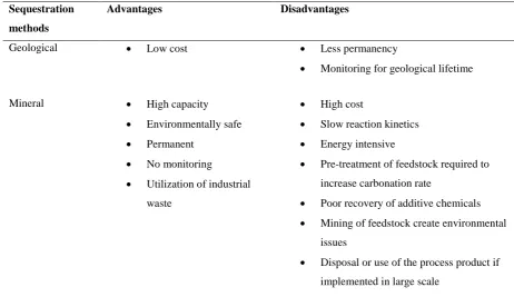
Table 5: Comparison of CO
2sequestration methods
Sequestration
methods
Advantages Disadvantages
Geological Low cost Less permanency
Monitoring for geological lifetime
Mineral High capacity
Environmentally safe
Permanent
No monitoring
Utilization of industrial
waste
High cost
Slow reaction kinetics
Energy intensive
Pre-treatment of feedstock required to
increase carbonation rate
Poor recovery of additive chemicals
Mining of feedstock create environmental
issues
Disposal or use of the process product if
implemented in large scale
IV CONCLUSION
This study discussed various aspect of CO2 sequestration. Four types of sequestration methods have been
described in details. These methods can be used to sequester CO2 and mitigate its effect on global warming.
However, adoption of any method depends on various parameters such as geological location, the amount of
sequestration required, and process cost.
REFERENCES
[1.] Bachu S (2000) Sequestration of CO2 in geological media: Criteria and approach for site selection in
response to climate change. Energy Convers Manag 41:953–970. doi:
10.1016/S0196-8904(99)00149-1
[2.] Baciocchi R, Costa G, Lategano E, et al (2010) Accelerated carbonation of different size fractions of
bottom ash from RDF incineration. Waste Manag 30:1310–1317. doi: 10.1016/j.wasman.2009.11.027
[3.] Bao W, Li H, Yi Z (2010) Selective leaching of steelmaking slag for indirect CO2 mineral
307 | P a g e
[4.] Brewer PG, Peltzer ET, Friederich G, et al (2000) Experiments on the ocean sequestration of fossil fuel
CO2: pH measurements and hydrate formation. Mar Chem 72:83–93. doi:
10.1016/S0304-4203(00)00074-8
[5.] Brierley AS, Kingsford MJ (2009) Impacts of Climate Change on Marine Organisms and Ecosystems.
Curr Biol 19:R602–R614. doi: 10.1016/j.cub.2009.05.046
[6.] Eloneva S, Teir S, Revitzer H, et al (2009) Reduction of CO2 Emissions from steel plants by using
steelmaking slags for production of marketable calcium carbonate. Steel Res Int 80:415–421. doi:
10.2374/sri09sp028
[7.] Gale J (2004) Geological storage of CO2: What do we know, where are the gaps and what more needs
to be done? Energy 29:1329–1338. doi: 10.1016/j.energy.2004.03.068
[8.] Goff F, Lackner KS (1998) Carbon dioxide sequestering using uitramaf IC rocks. Environ Geosci
5:89–101. doi: 10.1046/j.1526-0984.1998.08014.x
[9.] Gunter WD, Wiwchar B, Perkins EH (1997) Aquifer disposal of CO2-rich Greenhouse Gases:
Extension of the time scale of experiment for CO2-sequestering reactions by geochemical modelling.
Mineral Petrol 59:121–140. doi: 10.1007/BF01163065
[10.]Hitch M, Ballantyne SM, Hindle SR (2010) Revaluing mine waste rock for carbon capture and storage.
Int J Mining, Reclam Environ 24:64–79. doi: 10.1080/17480930902843102
[11.]Holloway S (2005) Underground sequestration of carbon dioxide - A viable greenhouse gas mitigation
option. Energy 30:2318–2333. doi: 10.1016/j.energy.2003.10.023
[12.]Huijgen WJJ, Comans RNJ (2003) Carbon dioxide sequestration by mineral carbonation, literature
review. Energy research Centre of the Netherlands (ECN)
[13.]IEA (2004) Energy Technology Analysis: Prospects for CO2 Capture and Storage. 249. doi:
10.1016/B978-1-85617-710-8.00010-8
[14.]IPCC (2005) IPCC Special Report on Carbon Dioxide Capture and Storage.
[15.]Lackner KS (2002) Carbonate Chemistry for Sequestering Fossil Carbon. Annu Rev Energy Environ
27:193–232. doi: 10.1146/annurev.energy.27.122001.083433
[16.]Levi RD (2005) Belvidere Asbestos Mine: Site Suitability for CO2 Sequestration Through Mineral.
[17.]Liu Z, Zhao J (2000) Contribution of carbonate rock weathering to the atmospheric CO2 sink. Environ
Geol 39:1053–1058.
[18.]Marini L (2007) Geological Sequestration of Carbon Dioxide - Thermodynamics, Kinetics, and
Reaction Path Modeling. Dev Geochemistry 11:27–51. doi: 10.1016/S0921-3198(06)80023-2
[19.]Motz H, Geiseler J (2001) Products of steel slags an opportunity to save natural resources. Waste
Manag 21:285–293. doi: 10.1016/S0956-053X(00)00102-1
[20.]O’Connor WK, Dahlin DC, Rush GE, et al (2002) Carbon dioxide sequestration by direct mineral
carbonation: Process mineralogy of feed and products. Miner Metall Process 19:95–101.
[21.]Park A-HA (2005) Carbon dioxide sequestration: chemical and physical activation f aqueous
308 | P a g e
[22.]Paustian K, Cole CV, Sauerbeck D, Sampson N (1998) CO2 mitigation by agriculture: An overview.
Clim. Change 40:135–162.
[23.]Ragnheidardottir EV (2010) Costs , Profitability and Potential Gains of the CarbFix Program.
[24.]Sanna A, Uibu M, Caramanna G, et al (2014) A review of mineral carbonation technologies to
sequester CO2. Chem Soc Rev 43:8049–80. doi: 10.1039/c4cs00035h
[25.]Sipilä J, Teir S, Zevenhoven R (2008) Carbon dioxide sequestration by mineral carbonation Literature
review update 2005–2007.
[26.]Sloan ED (2003) Fundamental principles and applications of natural gas hydrates. Nature 426:353. doi:
10.1038/nature02135
[27.]Teir S, Eloneva S, Fogelholm CJ, Zevenhoven R (2007) Dissolution of steelmaking slags in acetic acid
for precipitated calcium carbonate production. Energy 32:528–539. doi: 10.1016/j.energy.2006.06.023
[28.]Voormeij DA, Simandl GJ (2004) Geological, ocean, and mineral CO2 sequestration options: A