a
Corresponding author: [email protected]
Inductive voltage divider calibration with sampling method
David Corminboeufa and Frédéric Overney
Federal Institute of Metrology METAS, Lindenweg 50, 3003 Bern-Wabern, Switzerland
Abstract.This paper presents an automatic system developed at METAS for the calibration of inductive voltage dividers (IVD). The used method is primary for the n/10 ratio. With the described improvements, the calibration of IVDs has been made easier, faster and more reproducible than with the manual system used before. The uncertainties which can be reached with this new system are 28Â10-9 for the in phase and quadrature parts at a frequency of 1 kHz.
1 Introduction
In 2000, METAS participated to the AC Voltage Ratio Key Comparison CCEM-K7 [1]. For that purpose, a specific bridge, based on the bootstrap method [2, 3] had been designed, set up and characterized. The results of the comparison confirmed the capacity of the bridge to calibrate inductive voltage dividers (IVDs) at a sub-ppm level. However, it also appeared that the many manipulations required to balance the bridge were quite time consuming, making a calibration service based on such systems tedious and not cost-effective.
It was therefore decided to develop an automated version of that bridge.
The automation of the balances has been realized using high resolution (24 bits) digital-to-analogue converters (ADCs) instead of an analogue source and auxiliary IVDs. Also, the lock-in amplifier, used to detect the zero current condition, has been replaced by a high resolution (24 bits) analogue-to-digital converter (ADC).
The resulting bridge is in fact semi-automated because the reference IVD, the IVD under test and the IVDs setting the guard voltage are still manual. The measurement capability has been extended and now covers a frequency range from 40 Hz to 10 kHz.
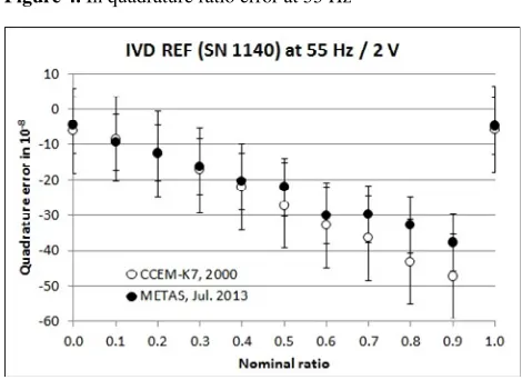
The validation of the new automated bridge has been carried out by comparing the measured error of our reference IVD to those obtained in 2000 during the Key Comparison CCEM-K7.
The next section recalls the principle of the bootstrap calibration method. Then, a detailed description of the setup is given, followed by a summary of the validation measurements done at 55 Hz and 1 kHz. Finally, the uncertainty budget is given.
2 Measurement principle
2.1 Comparison method
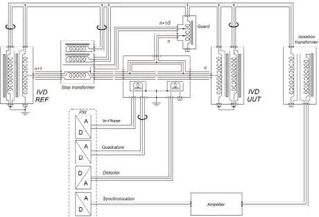
The comparison method allows the measurement of the difference of the output voltage of two IVDs. If the output voltage of one IVD (IVD REF) is known, the output voltage of the second IVD (IVD UUT) can then be determined. As shown in Figure 1, the two IVDs are powered by the same voltage source via an isolation transformer to avoid ground loops and to protect the IVDs against residual DC voltages. Between the two IVD outputs a current comparator containing two 100 to 1 transformers is connected. One transformer is used for the current detection and the other for the voltage injection required to balance the bridge. The injection circuitry consists of two sources, one in phase and one in quadrature (90 degrees phase shift) with respect to the input source. When the bridge is balanced, the injection voltage is 100 times the difference of the output voltage of the two IVDs under no load condition. To avoid any capacitive leakage current through the shield of the triaxial cable, the most inner shield is maintained at the same potential as the centre conductor by the guard IVD.
When the detector voltage is null, then:
(1)
With:
: input voltage of IVD REF
: input voltage of IVD UUT
: ratio number
: division ratio : n ratio error of IVD REF : n ratio error of IVD UUT
Figure 1. Schematic of the bridge used for the comparison method
2.2 Bootstrap method
The bootstrap method consists of two sets of measurements [4]. The first one was presented above in 2.1. The second, described in Figure 2, requires the
addition of a step transformer to compare the ratio n of one IVD with the ratio n+1 of the second IVD. The step transformer produces a voltage equal to one step of the IVD.
According to the diagram in Figure 2, when the detector voltage is null, then:
(2)
With:
: output voltage of the step transformer : ratio error of the step transformer
: injection voltage
Eliminating
from (1) and (2):
(3)
Dividing by , we have :
! "
#
!
$
!
(4)
When we add the equations for all values of n, we obtain:
% % & ! "
#
!
'
(% (5)
Using equation (5) we can calculate the error of the step transformer. After that we can calculate the error of each step of the IVD with the equation (4).
The two values % and % are just the errors of the ratios 1 and 0 respectively and can be easily obtained connecting the current comparator between the output and the high potential of the input for the ratio 1 and between the output and the low potential of the input for the ratio 0.
3 System description
This section provides a more detailed explanation of the most important components of this coaxial bridge. The current comparator and the step transformer have been developed in-house, the rest are commercial devices.
3.1 Sampling system
The sampling system is composed of a PXI chassis and two boards type NI-PXI4461 from National Instruments [5]. These two boards contain two 24 bit ADCs and two 24 bit DACs each. The maximum sampling rate is 204.8 kS/s (kilo samples per second) and the maximum peak amplitude is ±10 V. This system is controlled by a computer connected via fiber optic. The software developed in LabVIEW is used to automatically balance the bridge.
3.2 Current comparator
The main purpose of the current comparator is to detect and balance the small voltage difference between the output of the UUT and the output of the reference IVD
(with or without the step transformer). If the phase and/or the amplitude of the voltages applied to the current comparator are not equal, a small current will flow along the central conductor of the triaxial cable shown in Fig. 2. This current will then be detected using a first 1 to 100 transformer. To balance this residual current, a small voltage (adjusted in amplitude and in phase) is injected in the central conductor using a second 1 to 100 transformer. To avoid errors due to leakage current, the potential of the innermost guard of the triaxial cable is set to the same potential than the central conductor [3, 6]. This guard is surrounded by a second grounded screen to prevent uncontrolled ground currents. Finally, a residual error due to the stray admittance remains, at the gap between the two 1 to 100 transformers, if the capacitances between the guard and the outermost screen are not symmetric [6]. To avoid this error, a moving part has been implemented and adjusted on the outermost screen according to [7].
3.3 Step transformer
The step transformer is the main device of the bootstrap method. It gives the reference voltage step between the ratio n of first IVD and the ratio n+1 of the second IVD. It has to be stable during the time of the measurement and, most importantly, it should not be sensitive to common mode voltage.
It is a two stages, double shielded transformer which consists of two windings wound around two magnetic cores [8]. The first winding (magnetising winding) is wound around the first core and the second winding (ratio winding) is wound around the two cores. Each winding has a copper overlaying electrical screen to avoid parasitic effects between the windings. The secondary winding is realized with a coaxial cable. The shield of this winding is fixed to the same potential as the centre conductor by the guard IVD to cancel the leakage current between the centre conductor and the shield. Each of the three windings is made with an annular wire back around the core to reduce sensitivity to external magnetic fields. This step transformer has a 10 to 1 ratio with 100 turns for the primary winding and 10 turns for the secondary winding and works at frequencies from 40 Hz to 10 kHz and a maximum voltage of 0.11 V/Hz.
3.4 Cables
All cables used in the bridge are coaxial except the cables linking the outputs of the two IVDs, which are triaxial. To satisfy the principle of a coaxial bridge, all currents flowing into the shield of a coaxial cable must be equal but of opposite sign to the current in the centre conductor [9]. When a loop is formed in the wiring, a current can appear in this shield due to a magnetic field. To equalize the currents between the shield and the centre conductor we must place a choke in the loop. A choke is a toroidal core around which a coaxial cable is wrapped. Four chokes are used in the bootstrap method (Figure 2).
4.1 Reference IVD
In 2000, our reference IVD was measured with the bridge used for the Key Comparison CCEM-K7 at the two frequencies of 55 Hz and 1000 Hz. This same reference IVD was measured with our new automated bridge by using the bootstrap method described in Section 2.1 and at the same frequencies to compare the results. Currently, we have only one step transformer with a ratio of 10 to 1, that is the reason why all the measurements have been carried out for the ratio n/10 with n = 0 to 10.
Figure 3. In phase ratio error at 55 Hz
Figure 4. In quadrature ratio error at 55 Hz
Figure 5. In phase ratio error at 1000 Hz
Figure 6. In quadrature ratio error at 1000 Hz
4.2 Drift of the reference IVD
In Figure 5, the difference between the results of the years 2000 and 2013 seems to be an offset. A drift of the IVD REF may explain this offset. To test the hypothesis, a fit was done with the results obtained in 2006 and 2007 with the same measurement system as used for CCEM-K7. The Figure 7 confirms this hypothesis. This drift is less obvious on the quadrature part.
Figure 7. Drift of the in phase ratio error at 1000 Hz
Figure 8. Drift of the in quadrature ratio error at 1000 Hz
As explained in Section 3.3, the important feature of the step transformer is its insensitivity to common mode. Secondary screening prevents leakage current by capacitive effect, but it induces a magnetic field proportional to the common mode voltage due to capacitive leakage current between the primary and secondary screens [10]. To eliminate this effect, a third series of measurements was performed by reversing the secondary of the step transformer and thus we compared the ratio n-1 of IVD REF with the ratio n the other IVD. This is a capacitive effect so it increases with the frequency. At a frequency of 1000 Hz this effect cannot be observed because it is smaller than the uncertainty (see Figure 9).
Figure 9. Difference between {n+1}-{n} and {n-1}-{n} measurements at 1000 Hz
On the other hand, with a frequency of 5000 Hz this effect appears quite clearly on the in phase part. This error can be compensated by taking the mean value of the results {n+1}-{n} and {n-1}-{n}.
Figure 10. Difference between {n+1}-{n} and {n-1}-{n} measurements at 5000 Hz
4.4 Verification measurements
Two additional sets of measurements were carried out to detect other possible systematic effects.
The first measurement is to inverse the two IVDs. After the comparison with the previous results we observed a
maximum deviation is 510-9 for the in phase ratio and the quadrature ratio.
The second measurement concerns the current comparator. The injection and detector transformers were inverted to check the symmetry of this device. The maximum deviation measured for the in phase ratio is 410-9 and for the quadrature ratio is 310-9. Neither of the two measurements gave significant correction compared to the uncertainty.
5 Uncertainty budget
From equation (4) we can extract three uncertainty components which contribute to the uncertainty budget of each ratio of the IVD. A fourth component can be added due the current comparator. All uncertainties of the equation (6) are B type and there are the same for the in phase and in quadrature part.
)
)*$
% )+,-
. )/
. )
011
. (6)
With:
) : uncertainty of the ratio error of the reference IVD
) *%$ : uncertainty of the error of the step transformer
)+,-
.: uncertainty due to the noise of the
injection
)/
.: uncertainty due to the linearity of the
injection
) 011
.: uncertainty due to the offset of the current
comparator
To complete the uncertainty budget, an A type component is added based on three sets of five measurements carried out between July and September 2013 at a frequency of 1000 Hz and with a source voltage of 5 V.
Table 1. Uncertainty budget for the in phase and quadrature ratio at 1000 Hz / 5V
Type u (10-9)
Step transformer B 2
Injection noise B 6
Injection linearity B 12
Current Comparator B 2
Repeatability A 3
U (k = 2) 28
6 Conclusion
The new measurement system allows to reach an uncertainty of 2810-9 at a frequency of 1 kHz and greatly simplifies the calibration of the IVDs. The balancing of the bridge is much faster than before and the reproducibility is remarkable. It also allows METAS to be primary for the measurement of voltage ratios, presently only for n/10 ratios. It would be important in the future to build a step transformer with a ratio 100 to 1 and another with a ratio 11 to 1 to fully cover the primary measurement range. An improvement should also be made to the step transformer by adding another shield between the screens of primary and secondary windings to reduce the sensitivity to the common mode.
References
1. http://kcdb.bipm.org/appendixB/KCDB_ApB_info. asp?cmp_idy=68&cmp_cod=CCEM-K7&prov=exalead 2. W. Sze, “An injection method for self-calibration of inductive voltage dividers,” J. Res. Nat Bur. Stand, vol. 72C, no. 1, 1968.
3. D. N. Homan and T. L. Zapf, “Two stage, guarded inductive voltage divider for use at 100 kHz,” ISA Trans, vol. 9, no. 3, pp. 201–209, 1970.
4. E.F. Dierikx, “AC Voltage Ratio Measurement at NMi.VSL”, Journal of Metrology of India, Vol. 18, No. 3, 2003; pp.183-189
5. F. Overney and B. Jeanneret “Realization of an inductance scale traceable to the quantum Hall effect using an automated synchronous sampling system”, Metrologia, 47, pp.690-698, 2010
6. K. Grohmann, “A step-up method for calibrating inductive voltage dividers up to 1 MHz,” IEEE Trans. Instrum. Meas., vol. IM–25, no. 4, pp. 516–518, Dec. 1976.
7. R. Hanke, “An improved straddling method with triaxial guards for the calibration of inductive voltage dividers at 1592 Hz,” IEEE Trans. Instrum. Meas., vol. 38, no. 5, pp. 974–978, 1989.
8. O. Thévenot, “ETALONNAGE DE
TRANSFORMATEURS ETALONS”, Mémoire de diplôme d’ingénieur C.N.A.M, 2003