IJEDR1504064
International Journal of Engineering Development and Research (www.ijedr.org)1
Department of EEE,1SNS College of Technology, Coimbatore,Tamil Nadu
________________________________________________________________________________________________________
Abstract - As the wind power penetration continues to increase, wind turbines are required to provide Low Voltage Ride-Through (LVRT) capability. To improve the low voltage ride-through (LVRT) capability of a wind turbine (WT) with Doubly Fed induction generator (DFIG), this paper deals with the implementation of a new model on the rotor side for enhancing the voltage dip during faults. The method comprises of auto switching Crowbar protection on to the rotor side for the enhancement of voltage and also a battery energy storage system (BESS) in the dc link side to reduce the ripples by absorbing the redundant power stored in the DC link capacitor. Generally , premature removal of crowbar does not achieve good results and post late removal will make the machine to absorb more reactive power from the grid so, an automatic Crowbar protection is been employed which automatically works according to the requirement. The combined protection and control strategy is being proposed in the simulation results.
IndexTerms - DFIG, BESS, LVRT, Crow bar, DC link Capacitor
________________________________________________________________________________________________________
I.INTRODUCTION
In recent years, wind energy has become one of the most important and promising sources of renewable energy, which demands additional transmission capacity and better means of maintaining system reliability. The evolution of technology related to wind turbines that present many advantages compared to the fixed speed wind turbines. These wind energy conversion systems are connected to the grid through Voltage Source Converters (VSC) to make variable speed operation possible. The system that will be analyzed is a variable speed wind generator is directly connected to the grid while the rotor is connected through a back-to-back converter which is designed to stand only a fraction of the generator rated power. The advantages of the active and reactive power regulate independently capacity and excitation converters requires small capacity, the doubly fed induction generator (DFIG) has been widely used in the wind power system [1] - [2] . The voltage drop on the grid side will still connect the doubly fed induction generator to the grid. In order to achieve this need to overcome the low voltage ride through (LVRT) problem. When a sudden voltage drop [4] in the power grid, the stator and rotor will induce over-current due to the electromagnetic coupling of the electromagnetic coupling of the double-fed generators, this time the output of grid-side converter is limited, this time the output of the grid-side converter is limited, the energy accumulated in the DC side will cause DC-side voltage increase. To protect the rotor side converter, should switch the protective devices (crowbar)[5] to short circuit the rotor of the doubly-fed generator, in order to protect the DC side capacitors and to enable the DC-side voltage stability generally use unloading unit to consume the excess energy of the DC side [4], [5] present a storage battery, but only analyzed smooth out the output powers or to maintain a desirable power output as the wind speed varies. A control scheme which is auto-switching the crowbar according to the size of the rotor current is adopted for the crowbar protection to decrease the adverse effects on the system which is caused by the Crowbar premature or too late removable. A cascaded control scheme is applied for the battery energy storage devices to attenuate the transients DC voltage ripple in the DC bus when voltage sags in power failure situations. This paper presents a new approach for and control strategy to improve the transient performance of the doubly fed induction generator DFIG. In this the wind form consist of six 1.5MW wind turbines is simulated to verify this method. Each DFIG is equipped with an active crowbar and a battery energy storage device.
II.MODELLING OF WIND TURBINE
IJEDR1504064
International Journal of Engineering Development and Research (www.ijedr.org)2
Fig. 1. Block Diagram of Doubly Fed Induction GeneratorIII.MODELLING AND CONTROLOF COMBINED SYSTEM
1)Modeling of Rotor Side Converter Controller :
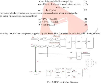
The Rotor Side Converter controls the Real and Reactive power output from the stator. The induction machine is controlled using synchronously rotating dq reference frame. The independent control is achieved by using this dq transformation. Using stator flux orientation method the relationship between the torque and the dq axis voltages, currents and fluxes can be described by the following equation
V d r= Rridr + σLrdidr/dt – ωslipσLriqr (1) Vqr = Rriqr + σLrdiqr/dt + ωslip(Lmims + σLridr) (2)
ωslip = ωs - ωr
σ = 1 – L02/(LsLr) (3) Where σ is a leakage factor. ωs, ωr are synchronous and rotor speed respectively.
The stator flux angle is calculated from
λαs=∫(Vαs – Rsiαs)dt (4) λβs = ∫(Vβs – Rsiβs)dt (5) θs = tan-1(λβs/λαs) (6)
Assuming that the reactive power supplied by the Rotor Side Converter is zero that is idr* is set to zero.
Fig. 2. RSC controller diagram
From rotor voltage equation we can get the d and q axis voltages as,
Vdr' = Rridr + σLrdidr/dt Vqr' = Rriqr + σLrdiqr/dt
The actual and reference values of idr and iqr are compared; the deviation value is given to the PI controller to reduce the steady state error.
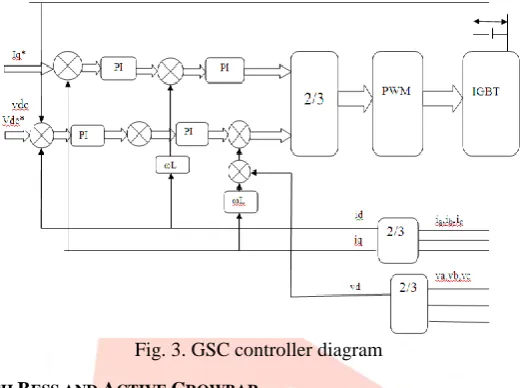
2)Grid Side Converter Model:
The grid side converter controls the dc link voltage independent of the magnitude and direction of rotor power. GSC also modeled with synchronously rotating reference frame with d axis regulates the dc-link voltage and q axis regulates the reactive power.
IJEDR1504064
International Journal of Engineering Development and Research (www.ijedr.org)3
Fig. 3. GSC controller diagramIV.MODELLING OF DFIG WITH BESS AND ACTIVE CROWBAR
The Proposed DFIG based wind turbine with active crowbar and battery energy storage system. An active crowbar is composed of Three-phase Diode Bridge in series with a bypass resistor and an IGBT power switch. A switching function x is defined for the power switch, which makes the value 1 (Activated) when the switch is closed and 0 for its open state (Deactivate). The dynamic behavior of such system during grid faults is very sensitive to the value of the bypass resistor; the resistor should be properly selected to limit the over current and also to avoid large voltage ripples in DC-link. The battery energy stores energy in the electromechanical form, and is the most widely used for energy storage in a variety of application. When the battery is discharging state is positive while in charging state is negative. The state- of- Charge is 100% and for an empty battery is 0%. The wind turbine is connected to the DFIG through a gearbox and a coupling shaft system. The three phase rotor windings are connected to the grid through back to back four quadrant PWM power converters and three phase stator winding is directly connected to the grid. Power captured by the wind turbine is converted into electrical power by the stator and rotor winding. A battery energy storage system is connected to the DC link capacitor through a bidirectional DC/DC converter.
IJEDR1504064
International Journal of Engineering Development and Research (www.ijedr.org)4
Fig. 4. Control strategy of the CrowbarV.SIMULATION RESULT
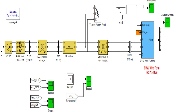
A wind farm consisting of 9MW wind turbine driven DFIGs with the battery energy storage system is simulated using Matlab/Simulink to verify the effectiveness of the proposed system combined protection and control strategy including the auto switching control for the operation of crowbar protection and the cascade control strategy under fault condition. The diagram shown in figure 4. In the active crowbar design, a reasonable selection of resistance of the discharge resistors is important. A larger quantity of resistance value may the transient decay faster, but the larger resistance value cause Over-voltage the rotor side, so that counter-charge DC bus capacitor, and may also damage the rotor side converter. After comprehensive consideration and simulation comparison, the discharge resistor chosen as 0.06 pu. Figure 5(a) shows that for normal operation of DFIG for variable wind speed the rotor speed is maintained constant. The performance of DFIG equipped with active crowbar under symmetrical 3 phase short circuit grid fault. The voltage drops 2 less than 20% of the nominal value at 0.5sec and the voltage sags last for 500ms. The rotor side current increased to 2 to 4 times of nominal value between 0.5s and 1s. Instead state the D.C link voltage is maintained at 1200V by the grid side converter. During the fault condition the threshold value of rotor current and DC voltage are set as 1.5pu and 1400V resp. from fig (b) to (c) shows the operation of DFIG without crowbar and BESS. From fig (d) to (g) shows the operation of DFIG with crowbar and BESS. Fig (h) shows the operation of BESS during fault condition i.e., State of Charge (SOC), current (I), Voltage (V). Fig (i) shows the switching operation of crowbar during fault interval. Fig 6 shows the different switching operation of crowbar in different fault condition that is LLL, LLLG, LLG, LL, LG faults. In the comparative study for different faults LG fault is least severe for that reason there is no crowbar switching.
IJEDR1504064
International Journal of Engineering Development and Research (www.ijedr.org)5
Fig.6. Operation of DFIG FOR LLL fault (dc-link & rotor current) without crowbar.Fig.7. Operation of DFIG FOR LLL fault (V-B575 & I-B575) without crowbar
Fig.8. Operation of DFIG FOR LLL fault (dc-link & rotor current) with crowbar
IJEDR1504064
International Journal of Engineering Development and Research (www.ijedr.org)6
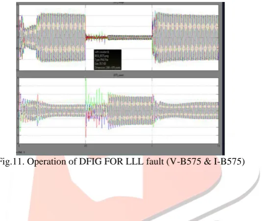
Fig 10. Operation of DFIG FOR LLL fault(DC-link & rotor current) with crowbar & BESS.Fig.11. Operation of DFIG FOR LLL fault (V-B575 & I-B575)
VI.CONCLUSIONS
The mentioned control staregy of the Active Crowbar are not same as conventional 1 , which can auto – switching the crowbar according to the size of rotor current .A combined protection and control strategy including Active Crowbar and Battery Energy Storage System has been presented to enhance the LVRT capability of a Wind turbine driven by DFIG. this paper also presented a BESS connected to DC bus which is controlled to attenuate the DC voltage ripple via absorbing the redundant power stored in DC link capacitor during power system on fault condition which can protect the DC side capacitor , does improved LVRT capability. The 9MW DFIG wind turbine system developed in simulink with a combined control strategy. Simulation results shows that the combined protection and control strategy can well protected the rotor side converter and the DC side capacitor during the power system on fault condition, thereby better improved LVRT capability. And a comparative study of crowbar switching is analyzed for different fault condition i.e., LLL, LLLG, LLG, LL, LG Faults according to its size of rotor
current. Future work will be done to satisfy the grid requirement powercompensation of DFIG operating undergo grid fault and
also to reduce harmonics in the system.
REFERENCES
[1] R.Pena, J. C. Clare, G. M. Asher, “Doubly fed Induction generator using back-to-back PWM Converters and its application to variable speed wind – energy generation,” IEE Proceedings Electrical Power Application,vol.143(3),pp.231–241,1996. [2] S. E. Aimani, B. Francois, B. Robyns, F. Minne, “ Modeling and Simulation of doubly fed induction generators for variable
speed wind turbines integrated in a distribution network,”Proceeeding of EPE 2003, Toulouse., Septmber 2013.
[3] J. K. Niiranen, “Simulation of Doubly fed Induction Generator Wind Turbine with an active Crowbar,” in EPE – PEMC, Latvia, 2004.
[4] J. Mooren, S. W. H. De Haan, “Ride through of wind turbines with doubly-fed induction generator suring a voltage dip,” IEEE Transcation Energy Conversion, Vol. 20, No.2, PP. 435-441, June 2005.
[5] X. Dawei, R. Li, P. J. Tavner, and S. Yang, "Control of a doubly fed induction generator in wind turbine during grid fau
ride-through," IEEE Transactions on Energy Conversion, vol. 21, pp. 652-662, 2006.
[6] J. I. Jang, Y. S. Kim, and D. C. Lee, "Active and reactive power control of DFIG for wind energy conversion under