Transverse Cracking of Rotor Shafts Based on Disk Shrunk Technology
Bruno Andrier 1),Laurent Capponi 2), Eric Garbay 1), Patrick Massin 3)
1)EDF/GDL – 2 Rue Ampère, 93206 Saint-Denis Cedex.
2)EDF/CAPE – Cap Ampère, 1 place Pleyel, 93282 Saint-Denis Cedex.
3)EDF/ Development and Research Division, 1 Avenue du Général de Gaulle, 92141 Clamart.
ABSTRACT
It is known from international feedback that the rotor shafts of the turbo-generators with disk shrunk technology may have transverse cracks located in the space between the disks and the central spacer which may be also shrunk on the shaft.
All of the 24 PWR 900 Mwe units of the EDF NPPs equipped with low pressure rotors are concerned with this technology. In October 1998 the ultrasonic inspection of a low pressure shaft revealed the presence of two cracks at the right of two keys of the central spacer, which was confirmed in 2001 by a destructive observation on a deposed shaft. From then on ultrasonic inspections have shown that the cracking phenomenon was generalized to the shafts of the 900 Mwe units equipped with disk shrunk technology.
Following this finding a research program was launched by EDF based on mechanical studies and experimental investigations. The aim of this program is to identify which operating conditions are limiting the life expectancy of the rotor shafts and to identify which margin exists with respect to brutal rupture of the shafts. Another important point of the program is to check which surveillance is well-suited for the type of crack shapes likely to occur.
It was understood that the cracks were initiated by the fretting between of keys and shaft and that they propagated with a fatigue mechanism under rotational bending of the shafts due to gravity effect. Analysing the deposed cracked shaft showed that the radial propagation occurred mainly during the 3800 hours of barring when the rotational speed was set to 75 rpm and inertia effects were negligible. Its circumferential extension was due to the 33000 hours of normal operating conditions at 1500 rpm during which rotational flexion effects due to gravity compete with a torsion effect due to the coupling of the shafts with the alternator. The crack shape is semi-elliptical, warped around the shaft axis like an helix.
A limit threshold for maximum crack depth is positioned at 100 mm with respect to the 960 mm diameter of the central spacer. A validation of this threshold is proposed based on the feedback exploitation, based on numerical results and interpretation of experimental results. Numerical results consist of stress intensity factors along the crack front obtained for different crack shapes and both barring and normal operating conditions. Kinetics are deduced from the stress intensity factors, mainly the mode I stress intensity factor KI related to the crack opening normal to the shaft axis.
∆KI variations of KI due to the rotational flexion may be used to determine the front crack propagation speed using a Paris law when pure mode I conditions are present and experimental data when several propagation modes exist simultaneously.
Analyses made on revolution and semi-elliptical cracks show a critical crack depth of 300 mm under normal operating conditions corresponding to the brutal rupture of the shaft. The rupture mode corresponds to torsion. This critical depth is obtained for a revolution crack which corresponds to the most unfavourable condition.
The values of ∆KI along the crack front show that when the crack is deeper than 50 mm, radial propagation is favoured in barring, which seems to be confirmed by the analysis of the opened crack. Under normal operating conditions values of ∆KI are uniform along the crack front, which seems contradictory with an absence of propagation in the radial direction. During the transition from barring to normal operating conditions a non-negligible drop of the value of ∆KI is observed at the centre of the crack which could inhibit the propagation during the latest operating conditions. This effect is added to the slowing effect of static mode III due to torsion when superposed to an alternate mode I. Specific experiments are currently conducted to provide us with the necessary experimental data.
KEY WORDS : cracks, propagation, shafts, combined modes, rotational bending. Transactions of the 17th International Conference on
Structural Mechanics in Reactor Technology (SMiRT 17) Prague, Czech Republic, August 17 –22, 2003
INTRODUCTION
In October 1998 the ultrasonic inspection of a low pressure shaft revealed the presence of two cracks at the right of two keys of the central spacer, which was confirmed in 2001 by a destructive observation on a deposed shaft. This shaft was the most affected with a 102 mm-deep crack with respect to a 960 mm diameter for its spacer. From then on ultrasonic inspections have shown that the cracking phenomenon was generalized to the shafts of the 900 Mwe units equipped with disk shrunk technology. Cracks are almost transverse to the shaft axis.
After initiation in the keys region, cracks propagate under fatigue due to an alternate bending loading. The bending results from gravity, and its variations result from the rotation of the shaft. Two main operating conditions will be investigated : barring at 75 rpm during which rotational bending effects are predominant and normal operating conditions at 1500 rpm during which these rotational bending effects compete with a torsion effect due to the coupling of the line shafts with the alternator.
A workshop composed of several teams from EDF and ALSTOM helped define a 100 mm-deep limit crack. This threshold was established using the experimental feedback from the deposed shaft, confirmed later by numerical investigations and the exploitation of experimental results. A research program based on mechanical studies and experimental investigations was launched by EDF. The aim of this program was to identify which operating conditions were limiting the life expectancy of the rotor shafts and to identify which margin existed with respect to brutal rupture of the shafts. Another important point of the program was to check which surveillance was well-suited for the type of likely crack shapes.
DESCRIPTION OF THE CRACKS
A shaft line is composed of three lined low pressure turbines connected to a high pressure turbine on one end and to the alternator that provides energy on the other end. The low pressure turbines are named LP1, LP2 and LP3 as you get closer to the alternator.
High pressure turbine side
Alternator side
Crack position Disks
Central Spacer
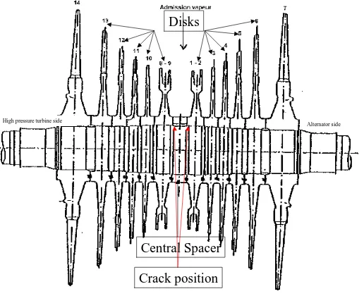
Fig. 1 Position of the cracks on the turbine
A low pressure turbine model is given on figure 1. The middle zone figures the central spacer. The spacer is linked to the shaft by the means of three keys 120° away from each other. Cracks are located at the right of the keys and several keys may be affected. Cracks develop in the zone between spacer and disk shrunk regions. Ultrasonic controls show that:
• The number of cracks is more important on the high pressure turbine side than on the alternator side for each LP;
• Crack depth is more important as the shaft distance with respect to the alternator increases, increasing from LP3 to LP1.
The position of the cracks on the shaft axis is indicated on figure 1. Cracks are almost transverse to the shaft axis. Their maximal depth is 102 mm measured with respect to the 960 mm diameter of the spacer. Crack shape is semi-elliptic warped in an helix-like way around the shaft axis.
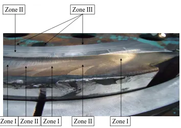
• Zone I : Plane propagation zones transverse to the shaft axis in mode I during baring phases, with both radial and circumferential extension. Numerous stop lines may be seen. Disk shrunk effect induce a static mode II that deviates the crack under the spacer.
• Zone II : Helix-shaped propagation zones, with roof like profile when the crack depth is maximal, generated in normal operating conditions with an alternate mode I and a static mode II near the extremities of the crack or a static mode III at the centre of the crack. The angle of the propagation plane with respect to the transverse to the axis of the shaft is about 7° in the case of the deposed LP1 turbine. Propagation is circumferential with no stop lines. This propagation process appears quickly.
• Zone III : Roof-like propagation zones in the last propagation band when successive to a zone II propagation type. Quasi-transverse propagation if consecutive to a zone I propagation type with a deviation of the crack towards the spacer. Propagation is essentially radial with numerous stop lines. This propagation occurs during barring because the angle of propagation is not compatible with the torsion torque in the normal operating conditions. Moreover specific experiments were conducted in alternate mode I on non-transverse cracks, inducing an alternate mode I+III, that showed that such factory roof profiles could be obtained.
Zone I
Zone II
Zone I
Zone II
Zone I
Zone III
Zone II
Fig. 2 : Propagation zones for the crack in the deposed LP1 turbine
METHODOLOGY FOR THE MECHANICAL STUDIES
The mechanical studies are based on the determination of the stress intensity factors that will be used to derive the kinetics of the crack propagation and establish the margin with respect to the brutal rupture risk. In the case analysed here, the critical threshold for brutal rupture is Kc equal to 220 MPa.m½. Both numerical analyses and analytical solutions, when available for the latest, are used. Different crack profiles are investigated : revolution, semi-elliptic and helix-shaped for different crack depths going from 50 mm up to 550 mm.
A long model of shaft is used in order to avoid boundary-dependency results. KI, KII, KIII stress intensity factors are determined in relation to the displacement field. KI corresponds to a mode I propagation with a crack opening normal to the surface of the crack. Stress intensity factor KII corresponds to a radial sliding and KIII to a circumferential sliding in the crack plane. The validity of the results KI, KII, KIII is checked in comparing the restitution energy rate obtained from an energetic method with that obtained in plane deformation in exploiting the stress intensity factors.
doesn't close for an alternate bending torque then ∆K1 equals KImax-KImin. Values of KII and KIII do depend on the operating conditions by the way of the torsion torque but are independent of the bending torque.
Stress intensity factors are used to determine the propagation kinetics. During barring, mode I is predominant and the kinetics is quite well represented by a Paris law. During normal operating conditions, kinetics is much more complicated since it encompasses alternate mode I and static mode II and mode III depending on the location on the front crack. A matching with experimental results for combined loading such as [2] is therefore necessary. Unfortunately, for this type of material, no results are available for alternate mode I and static mode II.
MODELS OF THE NUMERICAL ANALYSIS
Version 5.5 of Code_Aster, the finite element code developed at the research development facility of EDF, was used. All the profiles evoked further up were meshed. In our studies a represents the depth of the crack, 2b denotes its circumferential extension and θ its inclination angle with respect to the plane normal to the shaft axis.
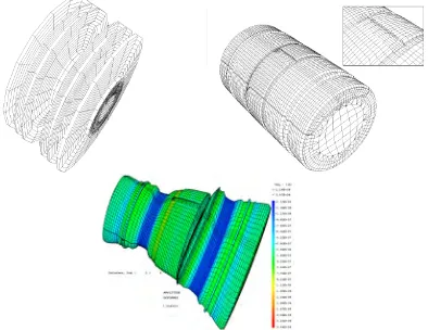
The models are globally symmetric with respect to the spacer. Their minimal length is 1.536 m and is dependent on the position of the turbine with respect to the alternator. The crack location may be on the alternator side or on the other side but it remains 128 mm away from the central spacer middle plane, position where most of the cracks are located. We studied revolution, semi-elliptic and helix-shaped cracks. A representative mesh may be seen on figure 3.
Fig. 3 : Representative mesh and bending-torsion effect on a 200 mm-deep crack in normal operating conditions. Displacements are amplified by 1000.
Material properties do not play an important role. As a matter of fact, for our loadings (bending and torsion) except fretting, stress intensity factors only depend on the stress field which is proportional to the applied torques and are not influenced by the material properties of the shaft. We used the following material properties corresponding to the 26NCDV14.7 steel of our shafts :
• Volumetric mass : ρ = 7800 kg/m³
• Young modulus : E = 205000 MPa
• Poisson's ratio : ν = 0.3
Other material properties are used to understand the physics of the rupture mechanism such as the conventional tensile yield strength Rp0.2 the value of which is about 770 MPa and the 880MPa ultimate tensile strength.
the 1500 rpm rotation in normal operating conditions is taken into account as a volumetric force. The inertia effect on the blades is however neglected in the present results: when taken into account it showed that our results were slightly more penalising since the stress intensity factors were 5% greater than the ones with inertia effect on the blades.
The meshes employed are mainly linear. Perfect contact conditions are applied on the crack surfaces : they are dealt with Lagrangian multipliers. Near the crack front line quadratic elements are used to improve the quality of the stress field. Barsoum elements with quarter nodes are used on the front line to properly deal with the singular stress field. These Barsoum elements are not affected by contact which allows a small and negligible penetration on the last row of elements of the crack front.
Boundary conditions are applied on the lateral faces of the portion of the rotor we modelled. One end of the shaft is clamped while on the other side bending and torsion torques are applied. The values of these torques are given by ALSTOM in [3] :
• Mbending = 1.47 MN.m
• Mtorsion = 5.84 MN.m value of the torque at the middle of the third low pressure turbine LP3
• Mtorsion = 4.34 MN.m value of the torque at the middle of the LP2
• Mtorsion = 2.84 MN.m value of the torque at the middle of the LP1
The torques on one side and Dirichlet conditions on the other side are applied on beam elements cinematically connected to the lateral face of the portion of turbine modelled.
RESULTS OF THE NUMERICAL ANALYSIS
Fretting effects are more important in barring than for normal operating conditions when they are compensated by rotating inertia effects. Fretting forces result in a mode I crack opening : without any other loading the value KIave obtained is always non-zero positive, decreasing as the crack depth grows. Non-zero positive KImin value are also found, due to this fretting, whatever the crack shape, provided its depth is lower than 50 mm. The bending torque that ought to close the crack is not high enough to compensate the fretting effects. For small crack depths lower than 50 mm the values of ∆KI=KImax-KImin are identical in barring and normal operating conditions, due to the sole effect of the rotating bending. For higher crack depths, it is only near the surface points of the cracks, when they exist, that the fretting maintains the crack opened so that ∆KI values are identical in barring and normal operating conditions. As the crack goes deeper away from the surface, closing effects become noticeable so that ∆KI=KImax. The value of ∆KI that is then evaluated takes into account the fretting. Fretting conditions being different for barring and normal operating conditions, values of ∆KI differ by a constant amount of 7 MPa.m½ for crack depths higher than 150 mm. They increase in keeping with the depth of the crack. Similarly, KIII increases for revolution cracks, while for semi-elliptic cracks both KII and KIII increase. For revolution cracks a very good agreement is found between the numerical results and the analytical expression issued from [4] for the term KIII :
+ + + + + − = 5 4 3 2
3 128 0,208
35 16 5 8 3 2 1 1 8 3 . 2 . 16 D d D d D d D d D d D d d D d T
KIII π
π
since no frictional effect was taken into account in the numerical analysis. In the above expression D is the diameter of the shaft, d is the diameter of the non-cracked part shaft and T the applied torque. For these cracks a 300 mm-deep limit crack is obtained for a LP3 turbine type. The rupture mode is shearing due to the torsion torque. As you switch from a revolution crack to an elliptical one you get a higher crack limit depth due to the fact that the non-cracked surface is more important for the latest configuration. If you increase the ratio a/b the stress intensity factors on the crack front decrease as the noxiousness of the crack is proportional to the crack surface.
The values of ∆KI depend on the type of rotor being observed. As a matter of fact it depends on the position of the crack plane with respect to the middle plane normal to the axis of the model. In that middle plane, axial stresses and deformations caused by bending are maximal. The nearer the crack is from that plane, the higher the values of
∆KI=KImax for crack depths superior to 50 mm. Therefore, we have to find that the values of ∆KI decrease from a crack opposite to the alternator on a LP3 turbine to the same crack on a LP1 turbine and decrease again from a crack on the alternator side on a LP1 turbine to the same crack on a LP3 turbine. We checked that this rule was verified for the results we had. Values of KII and KIII also depend on the type of turbine as the torque is multiplied by two from LP1 to LP3. Variations of KII and KIII are proportional to the torque applied.
we are able to establish roughly that the radial crack propagation from 30 mm depth to 100 mm occurred during the 3800 barring hours.
For barring we use a simple experimental Paris law of the following type :
(
)
mI K C dN
da
∆
= mm/cycle
where a is the crack length or depth in mm and N the number of cycles of alternate bending. C and m are material characteristics set to 3.458 E-09 and 3.06 for 26NCDV14-7 steel [5]. The non-propagation threshold is established at 7.5 MPa.m½ which corresponds to an experimental propagation speed lower than 10-6 mm/cycle for which one may consider that propagation has ceased. The values obtained for ∆KI for cracks deeper than 50 mm are well above the non-propagation threshold. Hence propagation is bound to occur. Moreover, relying on the crack profiles observed semi-elliptical cracks evolved from an a/b ratio of 1 about 30 mm depth to 0.4 about 50-75 mm depth and to 0.2 for 100 mm depth. With an extrapolation of the kinetics for cracks less than 50 mm-deep we may then establish that 2300 barring hours were necessary to pass from a 30 mm-deep crack to a 100 mm-deep crack. This estimated number is in the order of magnitude of the 3800 hours spent on barring in the case of the deposed shaft.
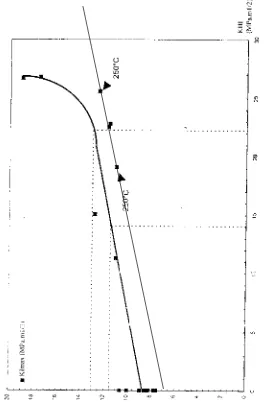
For normal operating conditions, identification is even more complicated since we only have partial experimental results that are due to be completed by mid-year. So far we have used experimental data for a loading ratio of 0.1 obtained from 10 mm-diameter revolution test specimens. The evolution of the non-propagation threshold in term of KImax for increasing values of KIII may be seen on figure 4. We can notice an increase of the threshold as the value of KIII grows. For all the cracks studied so far the ∆KI values are above the non-propagation threshold. Hence with the experimental data presently at our disposal we are not able to explain a stopped propagation at the centre of the crack.
Fig. 4 Evolutions of the non-propagation threshold KImax with respect to KIII for 20°C (thick line) and 250°C (thin line) and a loading ratio of 0.1. University of Besançon.
DISCUSSION
The main numerical results are listed below :
• ∆K1 identical for barring and normal operating conditions on all the front crack points for crack depths lower than 50 mm.
• ∆K1 identical for barring and normal operating conditions on the near surface points of the front crack for all crack depths.
• ∆K1 smaller at the centre of the crack for normal operating conditions than for barring for crack depths grower than 50 mm. For crack depths superior to 100 mm, the drop of ∆K1 between barring and normal operating conditions stabilises about 7 MPa.m½.
• ∆K1 smaller for cracks on the alternator side than for cracks on the high pressure side, for an identical axial position.
• K3 at the centre crack point and K2 at the extreme crack points are proportional to the torsion torque in normal operating conditions. Their values is multiplied by two as you switch from LP1 to LP3.
Ultrasonic controls show that :
• The crack depth is more important for LP1 than for LP2, and for LP2 than for LP3.
Observation of the crack of the deposed shaft shows that :
• Radial propagation occurred during barring only.
• Propagation in normal operating conditions appears later than that in barring and the crack from normal operating conditions is initiated on the side of the propagated crack in barring.
• The deeper the crack obtained from barring, the nearer from the surface of the shaft the initiation point of the normal operating crack conditions is located.
• Propagation in normal operating conditions is mainly circumferential.
The experimental investigations implemented provide us with the following information :
• Non-propagation threshold for barring at 20°C is between 7 and 8 MPa.m½.
• Non-propagation threshold increases in normal operating conditions because of the presence of an increasing K3 static mode. The non-propagation threshold increases as the loading ratio decreases [6]. The non-propagation threshold decreases as temperature increases [7]. New experimental results have to be obtained for a loading ratio of -0,7 and a temperature of 250°C. They will complete the results we already have for a loading ratio of 0.1.
Other experimental results from the literature give us the following hints :
• When using sequences of ∆KI, switching from a high value to a lower one, propagation may be inhibited for the lower value of ∆KI. Propagation speed is then lower than that obtained for the lower value only without sequencing. Propagations may even be observed to stop [8]. The reverse sequence doesn't have any effect on the propagation speed and no acceleration or retardation effect can be seen.
• The superposition of a static mode II to a rotating mode I with an open crack leads to a greater propagation speed than in the case of the sole rotating mode I [9].
• A scale effect was observed for 10 and 14 mm diameter test specimen with semi-elliptical defects [10][11]. The propagation speed for an alternate mode I and a static mode III was slower for the specimen with the greater diameter.
The following correlation between numerical results, experimental results and literature may be drawn :
• The estimated values of ∆ΚΙ are greater on the side of the high pressure turbine than on that of the alternator. This result is in agreement with the fact that the detected number of cracks is more important on the high pressure turbine side than on that of the alternator.
• Numerical results have shown that for small cracks, values of ∆KI did not vary from barring to normal operating conditions, due to the sole bending effects. For such cracks, with a ratio a/b about 1 (penny-shaped cracks) circumferential extension is favoured both in barring and normal operating conditions. Numerical results and the fracture profile concord on that point too.
• For cracks deeper than 50 mm the value of ∆KI drops from barring to normal conditions but remains identical at the near surface points. In case of barring, the value of ∆KI is greater at the centre of the crack. Radial propagation is favoured. In normal operating conditions, due to the rotation and to the fact that the crack is closed on most of its front, the value of ∆KI is homogeneous on the crack front, which could seem contradictory with the fact that the propagation is mostly circumferential in that situation. But, then values of KIII at the centre of the crack become more important and double as you switch from LP1 to LP3. Propagation is then surely retarded and that retardation effect is more important for the LP3 configuration which may also explain why the cracks on LP3 turbines are less deep. Then at the crack centre one should not overlook that the value of ∆KI drops from barring to normal conditions which could lead to a retarded or stopped propagation still to be evaluated in the situation analysed so far. The combination of these two effects (unloading at the centre of the crack and superposed static mode III to a rotating mode I) may account for the absence of propagation in the radial direction observed on the analysed crack.
• In normal operating conditions propagation must be favoured near the shaft surface, thus circumferentially, where the crack remains open and a static mode II is superposed to the rotational bending mode.
CONCLUDING REMARKS
Using the experimental feedback from the deposed shaft a limit crack depth is currently fixed at 100 mm. Numerical and analytical investigations have shown that in normal operating conditions a depth of 300 mm could still be accepted and did not lead to brutal rupture. This limit depth is obtained for a revolution crack on a LP3 turbine when the torsion torque is most important. The rupture mode corresponds to the shearing due to the torsion torque applied. Further extension of this program consists in obtaining limit crack depth for more unusual loading such as the ones that might occur during short-circuits or false-coupling.
During barring, kinematics analysis shows that the radial propagation speed at a depth of 200 mm is twice that of a depth of 100 mm. At a depth of 300 mm the radial propagation speed is ten times that of 100 mm. Material analyses are still being implemented to show that the radial propagation is inhibited in normal operating conditions, for which the time spent is ten times that of barring. If these material analyses prove successful, then the exploitation crack limit of 100 mm will be comforted. As a matter of fact radial propagation will be proven to occur only during barring, the crack propagation being circumferential in normal operating conditions.
Then as the time spent in normal operating conditions is much longer than that spent on barring, it is impossible to exclude a potential circumferential development of the cracks. Such crack profiles may not be detectable with all vibratory surveillance systems. For example, systems relying on the observation of the bending harmonics of the rotational speed which are sensitive to the variation of the flexural stiffness of the structure will certainly be useless. Therefore, this study shows clearly that other methods ought to be used in that case, such as the surveillance of bending or torsion modes which are sensitive to these crack profiles that may be seen through their shift displacement action on these modes.
REFERENCES
[1] L. Capponi, E. Garbay, P. Gruau and al , "Turbines CP0-CP1 : Fissuration transverse des arbres de rotors BP à technologie frettée ", Congrès de Fontevraud, 2002, Réf 7-KN-117.
[2] F. Hourlier , "Propagation des fissures de fatigue sous sollicitations polymodales ", PhD Thesis 1982.
[3] P. Gruau , "CP1- Rotors BP Frettés – Fissure transverse. Groupe de travail EDF-ALSTOM « aptitude au service des rotors fissurés ». Synthèse des calculs effectués par Alstom durant la période 1999-2000", note ALSTOM STDF2 02-025, 10/09/02.
[4] Hiroshi Tada, P.C. Harris and G.R. Irwin, The stress analysis of cracks handbook, Dell Research Corporation, Hellertown, Pennsylvania, 1973.
[5] B. Marandet, "Etude en mécanique de la rupture des aciers pour disques de rotors BP de turbines à vapeur des tranches nucléaires à eau ordinaire ", Rapport technique sur les essais réalisés à l’IRSID.
[6] E.K. Tschegg et al., "Influence of constant mode III load on mode I fatigue crack growth thresholds.",
Fatigue under biaxial and multiaxial loading, ESIS 10, 1991, pp. 213-222.
[7] P.K. Liaw et al., "Influence of temperature and load ratio on near-threshold fatigue crack growth thresholds", Fatigue thresholds concepts, 1983, pp. 205-223.
[8] H. Nayeb-Hashemi, F.A. McClintock, R.O. Ritchie, "Influence of overloads and block loading sequences on mode III fatigue crack propagation in A469 rotor steel ", Engineering Fracture Mechanics, Vol.18,No4,pp.763-783,1983.
[9] Stanzl E.S. and al., "Fatigue crack-growth under combined mode 1 and mode 2 loading ", 20th
Symposium on Fracture Mechanics. Perspectives and directions, June 1987, ASTM.
[10] M.A. Fonte and M.M. Freitas, "Semi-elliptical fatigue crack-growth under rotating or reversed bending combined with steady torsion ", Fatigue Fracture Engineering Mater. Struct., Vol.20, No.6, pp. 895-906, 1997.