A Hardware Interface for Hashing Algorithms
December 17, 2008
Zhimin Chen, Sergey Morozov, Patrick Schaumont
Bradley Department of Electrical and Computer Engineering
Virginia Tech
Blacksburg, VA
{chenzm,morozovs,schaum}@vt.edu
Abstract.
The submissions to the SHA-3 competition include a
refer-ence implementation in C, built on top of a standard programmer's
inter-face (API). This greatly improves the evaluation process: it enables
por-tability across platforms, and it makes performance comparison of the
algorithms easy. For hardware crypto-implementations, such a standard
interface does not exist. As a result, the evaluation and comparison of
hardware hashing algorithms becomes complex and error prone. The
first step to improve the evaluation process for hardware is the
defini-tion of an interface. This document describes a general hardware
inter-face for hashing algorithms. The operation of the interinter-face is discussed,
and the appendix lists a SHA-256 reference implementation that uses
the interface.
1
Introduction
Standard interfaces are the key to creating reusable and composable designs, and they
decouple module designers from module users. In software design, the use of standard
interfaces is a very common and almost universal practice. In the SHA-3 contest, a
standard Application Programmers Interface
1is used as a mechanism to make the
evaluation and comparison of the submissions easy. A software benchmarking
envi-ronment such as eBASH
2relies on a standard API to automate the performance
evalu-ation process. Besides standard interfaces, the software community also relies heavily
on open-source evaluation, which allows a given design to be tested by the community
on a wide range of platforms.
make comparisons based on the implementation efficiency of a design in a given
tar-get technology (area, critical path). The resulting performance numbers ignore the
module interface, or assume that the interface has infinite bandwidth.
This is problematic. In practice, the assumption of infinite I/O bandwidth is very
hard to approximate. Moreover, when algorithms with different input/output
require-ments are compared under the assumption of ideal I/O, the practical achievable results
may even contradict the
ideal
performance comparison. A further complication is that
hardware designers are not used to sharing source code, and their community does not
force them to do so. The SHA-3 competition, on the other hand, can benefit from an
open-source approach in software as well as in hardware.
The purpose of this document is to describe a generic hardware interface for a
hashing algorithm. The objective is not to make the fastest possible I/O interface, but
instead an interface which would do well across a wide range of designs. We have
evaluated the interface on several hashing algorithms - the appendix lists SHA-256 as
an example - and plan to port SHA-3 candidates to this interface as well. We welcome
feedback to the interface and would like to make it as useful as possible to the
com-munity.
2
Hardware Interface
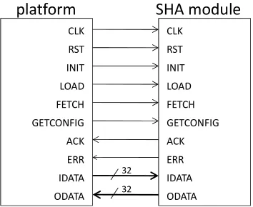
The hardware interface is a synchronous interface. Each input/output is sampled at the
rising clock edge. The interface control signals enable data transfer to and from the
hardware SHA implementation. The width of the data bus to/from the hardware SHA
implementation is unspecified, but will generally be a 'natural' wordlength for data
transfer (eg. 32 or 64 bits). It is the task of the platform encapsulation module to make
additional adjustments to this wordlength, if needed. The following signals are defined
on the low-level HW interface.
platform
CLK
RST
INIT
LOAD
FETCH
GETCONFIG
ACK
ERR
IDATA
ODATA
SHA module
CLK
RST
INIT
LOAD
FETCH
GETCONFIG
ACK
ERR
IDATA
ODATA
32 32
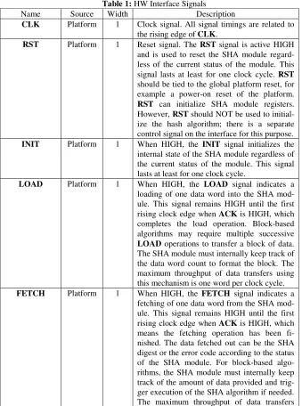
2.1 Port Signal Definition
This section contains an overview of the SHA-FPGA HW interface signals.
Table 1:
HW Interface Signals
Name
Source
Width
Description
CLK
Platform
1
Clock signal. All signal timings are related to
the rising edge of
CLK
.
RST
Platform
1
Reset signal. The
RST
signal is active HIGH
and is used to reset the SHA module
regard-less of the current status of the module. This
signal lasts at least for one clock cycle.
RST
should be tied to the global platform reset, for
example a power-on reset of the platform.
RST
can initialize SHA module registers.
However,
RST
should NOT be used to
initial-ize the hash algorithm; there is a separate
control signal on the interface for this purpose.
INIT
Platform
1
When HIGH, the
INIT
signal initializes the
internal state of the SHA module regardless of
the current status of the module. This signal
lasts at least for one clock cycle.
LOAD
Platform
1
When HIGH, the
LOAD
signal indicates a
loading of one data word into the SHA
mod-ule. This signal remains HIGH until the first
rising clock edge when
ACK
is HIGH, which
completes the load operation. Block-based
algorithms may require multiple successive
LOAD
operations to transfer a block of data.
The SHA module must internally keep track of
the data word count to format the block. The
maximum throughput of data transfers using
this mechanism is one word per clock cycle.
trig-using this mechanism is one word per clock
cycle.
GETCONFIG
Platform
1
When HIGH, the
GETCONFIG
signal
indi-cates reading of the configuration word from
the SHA module. This signal remains HIGH
until the first rising clock edge when
ACK
is
HIGH, which means the reading operation has
been finished.
ACK
SHA
1
The
ACK
signal is raised HIGH in response to
LOAD
,
FETCH
, or
GETCONFIG
to signal
a successful data transfer is possible. The data
will be transferred at the first rising clock edge
when both
ACK
and one of
LOAD
,
FETCH
or
GETCONFIG
are HIGH.
ERR
SHA
1
When HIGH, the
ERR
signal indicates that an
error occurs inside the SHA module. It is the
responsibility of the SHA module to generate
an error code (one word).
FETCH
operation
reads out the error code when
ERR
signal is
HIGH
.
INIT
and
RST
operations reset the
ERR
signal to LOW.
IDATA
Platform
Var
Input data word to the SHA module.
IDATA
is used to transfer data from the platform to
the SHA module during
LOAD
operations.
The word length is 32 bits in this version. It
will be extended to allow for higher bandwidth
(64 and 128 bits) operation in the future.
ODATA
SHA
Var
Output data word from the SHA module.
ODATA
is used to transfer data from the SHA
module to the platform during
FETCH
and
2.2 Data Organization
2.2.1 IDATA and ODATA
The bit/byte organization of a data word will use the same conversion as for the
FIPS-197 AES standard and is summarized as follows. Bits in the input sequence are
counted right to left. Bits in a byte are numbered from left to right, ie. b7, b6, b5, …,
b1, b0. Bytes in a byte array are numbered right to left, ie. byte0, byte1, byte2, ….
Thus, a data word of 1111000011001100 will correspond to the following byte
se-quence: 0xF0, 0x66. In a block of data, words are organized right to left, i.e. word0,
word1, word2.
Byte
Word
Block
byte0 byte1 byte2 byte3
word0 word1 word2 word3 word4 word5
0 1 2 3 4 5 6 7
Figure 2: Data organization of IDATA and ODATA
2.2.2 GETCONFIG
The SHA module provides a configuration word for the platform that enables the
platform to obtain basic I/O characteristics of the SHA module. The platform will
normally request the GETCONFIG word just after reset of the SHA module. The
resulting information may be used to configure hardware and software resources in the
platform.
Figure 3 illustrates the format of the GETCONFIG word. It contains 4 fields,
for-matted in a 32-bit word.
ca-•
input streaming
(bit 30): When this bit is 1, the SHA module will
ALWAYS read data block from IDATA using back-to-back transfers.
Once the first word of a block is transferred using LOAD, all subsequent
words of the same block will be read in consecutive clock cycles. For
SHA modules with hardware padding capacity, input streaming is not
sup-ported.
•
padding
(bit 29): When this bit is 1, the SHA module has word-level
pad-ding capabilities in hardware. This means that the loapad-ding of a data block
through LOAD commands is incomplete when the first FETCH command
is given, the SHA module will perform automatic padding on the partially
loaded block.
•
outblocksize
(bit 23 .. bit 16): The number of words in the digest
calcu-lated by the SHA module. This number corresponds to the number of
FETCH commands required to transfer an output data block.
•
inblocksize
(bit 15 .. bit 0): The number of words in the input data block
provided to the SHA module. This number corresponds to the number of
LOAD commands required to transfer an input data block.
b31 b29
b23 .. b16
b15 .. b0
output
streaming
padding
outblocksize
inblocksize
input
streaming
Figure 3: Definition of the GETCONFIG word.
2.2.3 ERROR
The SHA module provides a error word for the platform that indicates the incorrect
status inside the SHA module. When
ERR
is HIGH, the platform reads out error word
by means of one
FETCH
. The resulting information may be used to handle the error.
Currently, only one error is defined.
•
incomplete block
(bit 0): For the SHA module without padding
ca-pacity, when the
FETCH
signal goes HIGH before a complete block
is loaded, the SHA module has no way to generate HASH digest. In
such case, the SHA output
ERR
HIGH, in the meantime, set this bit
2.3 Communication Protocol
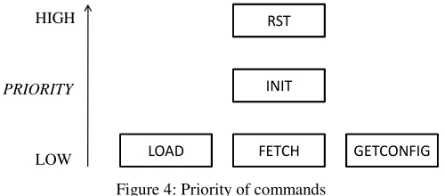
2.3.1 Command Priority
There are 5 different commands from the platform to the SHA module,
in-cluding
RST
,
INIT
,
LOAD
,
FETCH
, and
GETCONFIG
. The priority of
these commands is defined as follows.
RST
INIT
GETCONFIG
FETCH
LOAD
HIGH
PRIORITY
LOW
Figure 4: Priority of commands
The platform MUST guarantee that
LOAD
,
FETCH
and
GETCONFIG
will NOT be HIGH at the same time.
There are two types of command sequences to the SHA module:
•
Single-phase commands use a single control signal from the platform
to the SHA module.
RST
and
INIT
are single-phase commands.
•
Two-phase commands use two control signals, one from the platform
to the SHA module, and one from the SHA module to the platform.
Two-phase commands are used when the SHA module must
acknowl-edge command completion with
ACK
.
LOAD
,
FETCH
, and
GETCONFIG
are two-phase commands.
2.3.2 RST
RST
is a single-phase command used to reset the SHA module. The
plat-form keeps
RST
signal HIGH for at least one clock cycle and does not expect
any feedback signal from the SHA module. Since
RST
has the highest priority,
2.3.3 INIT
INIT
is a single-phase command used to initialize the SHA module by the
platform. The platform keeps
INIT
signal HIGH for at least one clock cycle
and does not expect any feedback signal from the SHA module. Since
INIT
has the higher priority than
LOAD
,
FETCH
, and
GETCONFIG
,
INIT
can
interrupt these three command operations and also interrupt the calculation
inside the SHA module.
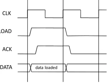
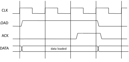
2.3.4 LOAD
LOAD
is a two-phase command used to
write one word into the SHA
module. LOAD is used in conjunction with the
ACK
control signal, and the
IDATA
data signal. The communication protocol of
LOAD
is similar to that
of the ‘write’ operation in a Bus. Figure 5 shows a simple transfer, one with
no wait states.
CLK
LOAD
ACK
IDATA
data loadedFigure 5: LOAD transfer with no wait states
In a simple transfer with no wait states:
1)
The platform drives
LOAD
HIGH after the first rising clock edge;
2)
The SHA module responds to
LOAD
by driving
ACK
HIGH before the
second rising clock edge;
3)
The platform samples
ACK
on the second rising clock edge;
4)
The SHA module then samples
IDATA
on the second rising clock edge;
5)
The platform drives
LOAD
LOW after the second rising clock edge, if
there no back-to-back
LOAD
after this one.
6)
The SHA module responds to
LOAD
(LOW) by driving
ACK
LOW
The SHA module could insert several wait states into a load transfer.
Sup-pose the SHA module wants to insert two wait states, as shown in Figure 6.
data loaded
CLK
LOAD
ACK
IDATA
Figure 6: LOAD transfer with two wait states
1)
The platform drives
LOAD
HIGH after the first rising clock edge;
2)
The SHA module keeps
ACK
LOW on the second and third rising clock
edge;
3)
The platform keeps
LOAD
HIGH until the fourth rising clock edge since
it does not sample a HIGH
ACK
on the second and the third rising clock
edge;
4)
The SHA module drives
ACK
HIGH after the third rising clock edge;
5)
The platform samples
ACK
on the fourth rising clock edge;
6)
The SHA module then samples
IDATA
on the fourth rising clock edge;
7)
The platform drives
LOAD
LOW after the fourth rising clock edge, if
there no back-to-back
LOAD
after this one.
8)
The SHA module responds to
LOAD
(LOW) by driving
ACK
LOW
before the fifth rising clock edge.
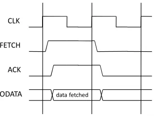
2.3.5 FETCH
FETCH
is a two-phase command used to retrieve data from the SHA
mod-ule.
FETCH
is used in conjunction with the
ACK
control signal and the
ODATA
data signal. When
ERR
is LOW
, FETCH
is used to
read one word
of the SHA digest from the SHA module; when
ERR
is HIGH,
FETCH
reads
out the error code. The communication protocol of
FETCH
is similar to that
CLK
FETCH
ACK
ODATA data fetched
Figure 7: FETCH transfer with no wait states
In a simple transfer with no wait states:
1)
The platform drives
FETCH
HIGH after the first rising clock edge;
2)
The SHA module responds to
FETCH
by driving
ACK
HIGH and
putting the output data to ODATA before the second rising clock edge;
3)
The platform samples
ACK
and
ODATA
on the second rising clock edge;
4)
The platform drives
FETCH
LOW after the second rising clock edge, if
there no back-to-back
FETCH
after this one.
5)
The SHA module responds to
FETCH
(LOW) by driving
ACK
LOW
before the third rising clock edge.
The SHA module could insert several wait states into a fetch transfer.
Sup-pose the SHA module wants to insert two wait states, as shown in Figure 8.
CLK
FETCH
ACK
ODATA data fetched
Figure 8: FETCH transfer with two wait states
1)
The platform drives
FETCH
HIGH after the first rising clock edge;
2)
The SHA module keeps
ACK
LOW on the second and third rising clock
edge;
3)
The platform keeps
FETCH
HIGH until the fourth rising clock edge
since it does not sample a HIGH
ACK
on the second and the third rising
4)
The SHA module drives
ACK
HIGH and puts the output data to
ODATA
after the third but before the fourth rising clock edge;
5)
The platform samples
ACK
and
ODATA
on the fourth rising clock edge;
6)
The platform drives
FETCH
LOW after the fourth rising clock edge, if
there no back-to-back
FETCH
after this one.
7)
The SHA module responds to
FETCH
(LOW) by driving
ACK
LOW
before the fifth rising clock edge.
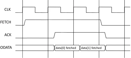
The platform also supports streaming data transfer. For some SHA modules,
once the output transfer is triggered, the HASH digest will be output in a
stream that is a back-to-back output sequence. This characteristic including
the number of words in a stream transfer should be indicated in the
configura-tion code (see Secconfigura-tion 1.2.2). Figure 9 presents an example of streaming
out-put with one wait state.
CLK
FETCH
ACK
ODATA data[0] fetched data[1] fetched
Figure 9: Two-word streaming FETCH transfer with one wait state
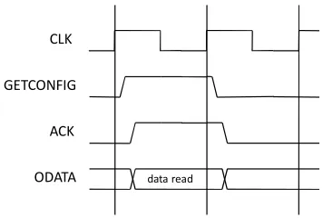
2.3.6 GETCONFIG
GETCONFIG
is used to
read the configuration word from the SHA
mod-ule. It is a two-phase command that works together with the
ODATA
and
ACK
signals. The communication protocol of
GETCONFIG
is exactly the
same as that of the
FETCH
operation. Figure 10 shows a simple transfer, one
CLK
GETCONFIG
ACK
ODATA data read
Figure 10: GETCONFIG transfer with no wait states
In a simple transfer with no wait states:
1)
The platform drives
GETCONFIG
HIGH after the first rising clock edge;
2)
The SHA module responds to
GETCONFIG
by driving
ACK
HIGH and
putting the output data to
ODATA
before the second rising clock edge;
3)
The platform samples
ACK
and
ODATA
on the second rising clock edge;
4)
The platform drives
GETCONFIG
LOW after the second rising clock
edge, if there no back-to-back
GETCONFIG
after this one.
The SHA module responds to
GETCONFIG
(LOW) by driving
ACK
LOW before the third rising clock edge.
The SHA module could insert several wait states into a fetch transfer.
Sup-pose the SHA module wants to insert two wait states, as shown in Figure 11.
CLK
GETCONFIG
ACK
ODATA data read
Figure 11: GETCONFIG transfer with two wait states
1)
The platform drives
GETCONFIG
HIGH after the first rising clock edge;
2)
The SHA module keeps
ACK
LOW on the second and third rising clock
edge;
edge since it does not sample a HIGH
ACK
on the second and the third
rising clock edge;
4)
The SHA module drives
ACK
HIGH and puts the output data to
ODATA
after the third but before the fourth rising clock edge;
5)
The platform samples
ACK
and
ODATA
on the fourth rising clock edge;
6)
The platform drives
GETCONFIG
LOW after the fourth rising clock
edge, if there no back-to-back
GETCONFIG
after this one.
7)
The SHA module responds to
GETCONFIG
(LOW) by driving
ACK
Appendix A: SHA-256 module in Verilog
/*
sha256 implementation Designer: Sergey Morozov
no data on init non-streaming fetch
getconfig implemented needs to be defined digest_ready internal only
10/02 - altered the busy signal to go high on the 15-16 round transition, as long as load was high
10/17 - fixed blocking assignments, synthesized
Timing constraint: Default period analysis for Clock 'clk' Clock period: 17.085ns (frequency: 58.531MHz)
Total number of paths / destination ports: 2687166063 / 2202
Device utilization summary: ---
Selected Device : 3s500eft256-5
Number of Slices: 1322 out of 4656 28% Number of Slice Flip Flops: 1101 out of 9312 11% Number of 4 input LUTs: 2456 out of 9312 26% Number of IOs: 71
Number of bonded IOBs: 71 out of 190 37% Number of GCLKs: 1 out of 24 4%
10/21 - added in an additional round to do the addback of hash value in order to reduce the overall critical path
10/27 - removed arrays+bit-subvectors combination
10/30 - making the change to make the command valid on busy
11/05 - the module is now matches the new testbench protocol (ack signal)
*/
module sha256 (clk, rst, init, load, fetch, ack, idata, odata, getconfig, error);
// preload constants
reg [31:0] K_ROUND_CONSTANTS [0:63];
initial
begin
$readmemh("k_constants.txt",K_ROUND_CONSTANTS, 0, 63); end
reg [31:0] H_INITIAL_CONSTANTS [0:7];
initial
begin
$readmemh("h_constants.txt",H_INITIAL_CONSTANTS, 0, 7); end
input clk;
input init;
input load;
input fetch;
input getconfig;
output ack;
reg busy;
reg digest_ready, data_valid, getconfig_responce;
integer count; //used in for loops
input [31:0] idata;
output reg [31:0] odata;
output error;
reg error_reg;
assign error = error_reg;
//stores the round of the hashing process
reg [7:0] round;
//store intermediate values during hash
reg[31:0] a, b, c, d, e, f, g, h;
// stores the input words from idata, and also the extended words for // rounds 16-64
reg[31:0] word [0:15];
reg[31:0] hash [0:7];
wire [31:0] main_s0, main_s1, main_maj, main_t1, main_t2, main_ch, k_constant, word_s0, word_s1;
wire [31:0] word1, word14;
wire [31:0] extended_word, current_word;
reg [3:0] digest_display;
// acknowledge signals
wire master_ack;
assign fetch_ack = fetch & data_valid & (|digest_display);
assign load_ack = load & (~busy);
assign getconfig_ack = getconfig & getconfig_responce;
assign master_ack = fetch_ack | load_ack | getconfig_ack;
assign ack = master_ack;
// main loop functions // (a rightrotate 2) xor // (a rightrotate 13) xor // (a rightrotate 22)
assign main_s0 = {a[1:0],a[31:2]} ^ {a[12:0],a[31:13]} ^ {a[21:0],a[31:22]};
// (a and b) xor (a and c) xor (b and c)
assign main_maj = (a & b) ^ (b & c) ^ (a & c);
// (e rightrotate 11) xor // (e rightrotate 25)
assign main_s1 = {e[5:0],e[31:6]} ^ {e[10:0],e[31:11]} ^ {e[24:0],e[31:25]};
// (e and f) xor ((not e) and g)
assign main_ch = (e & f) ^ (~e & g);
assign k_constant = K_ROUND_CONSTANTS[round%64];
assign main_t1 = h + main_s1 + k_constant + current_word + main_ch;
assign word1 = word[1];
assign word14 = word[14];
// (word[1] rightrotate 7) xor // (word[1] rightrotate 18) xor // (word[1] rightshift 3)
assign word_s0 = {word1[6:0],word1[31:7]} ^ {word1[17:0],word1[31:18]} ^ {3'b000,word1[31:3]};
// (word[14] rightrotate 17) xor // (word[14] rightrotate 19) xor // (word[14] rightshift 10]);
assign word_s1 = {word14[16:0],word14[31:17]} ^ {word14[18:0],word14[31:19]} ^ {10'b00_0000_0000,word14[31:10]};
assign extended_word = word[0] + word_s0 + word[9] + word_s1;
// for rounds 0-15 the idata is used for input word // for the other rounds the extended word is used
assign current_word = ((round < 'd16) | digest_ready) ? idata : extended_word;
always @(posedge clk) begin
data_valid <= fetch;
getconfig_responce <= getconfig;
end
always @(posedge clk or posedge rst) begin
//reset operation and clear hash values if (rst) begin //reset operation digest_ready <= 'b0;
digest_display <= 'd0; odata <= 'd0;
busy <= 'b0; round <= 'b0; error_reg <= 'b0;
// these are not strictly necessary to reset, // they are used "safely" in the rest of the module a <= 0; b <= 0; c <= 0;
d <= 0; e <= 0; f <= 0; g <= 0; h <= 0;
for( count =0; count < 8; count = count +1) begin
for( count =0; count < 32; count = count +1) begin
word[count] <= 0; end
end
else begin if (init) begin digest_display <= 'd0; digest_ready <= 'b0; round <= 'd0; odata <= 'd0; error_reg <= 'b0; busy <= 'b0;
for( count =0; count < 8; count = count +1) begin
hash[count] <= H_INITIAL_CONSTANTS[count]; end
a <= H_INITIAL_CONSTANTS[0]; b <= H_INITIAL_CONSTANTS[1]; c <= H_INITIAL_CONSTANTS[2]; d <= H_INITIAL_CONSTANTS[3]; e <= H_INITIAL_CONSTANTS[4]; f <= H_INITIAL_CONSTANTS[5]; g <= H_INITIAL_CONSTANTS[6]; h <= H_INITIAL_CONSTANTS[7]; end
else if ((~busy)) begin
// when the module is not busy operation is
// based input signals (init, load, fetch, getconfig) // will receive 16th input word on the next round and // go busy to calculate the hash for the block
if (load && (round == 'd15)) begin
busy <= 'b1;
word[round] <= idata; round <= round + 1; digest_ready <= 'b0; digest_display <= 'd0;
a <= main_t1 + main_t2; b <= a;
c <= b; d <= c;
e <= d + main_t1; f <= e;
g <= f; h <= g; end
// taking in input words and calculating the // intermediate hash value
else if (load && (round < 'd15)) begin word[round] <= idata;
a <= main_t1 + main_t2; b <= a;
c <= b; d <= c;
e <= d + main_t1; f <= e;
g <= f; h <= g;
end
// displaying the digest
else if (digest_ready && digest_display > 'd0) begin if (digest_display >= 'h8) digest_display <= 'd0; else begin
odata <= hash[digest_display%8]; digest_display <= digest_display + 'b1; end
end
// trigger digest display
else if (digest_ready && fetch) begin
odata <= hash[0]; digest_display <= 'd1; end
else if (fetch && (~digest_ready)) begin
busy <= 'd127; error_reg <= 'b1; digest_ready <= 'b1; digest_display <= 'b1;
odata <= 32'hdeaddead; //error code end
// need to put actual getconfig data into here // cannot recall the specific arrangement of bits else if (getconfig) begin
odata <= {1'b1,1'b0, 14'd8, 16'd16}; end
else begin
busy <= 'b0; end
end //end if (~busy)
else begin // if busy is high operation is based on internal // state, input signals are not considered
if ((round > 'd15) && (round < 'd63)) begin // continuing execution after all load are done
// downshift word[] every round to accomodate new extended_word for (count = 0; count < 15; count = count +1)
begin
word[count] <= word[count+1]; end
word[15] <= extended_word; round <= round + 1;
e <= d + main_t1; d <= c;
c <= b; b <= a;
a <= main_t1 + main_t2; end
// last true round of operation, no need to compute the // extended_word or to shift word this time
else if (round == 'd63) begin
round <= round + 1;
h <= g; g <= f; f <= e;
e <= d + main_t1; d <= c;
c <= b; b <= a;
a <= main_t1 + main_t2; end
// update the hash values with values from the previous // block the module is finished with the current data block // after this
else if (round == 'd64) begin
digest_ready <= 'b1; round <= 'd0; busy <= 'b0;
hash[0] <= hash[0] + a; hash[1] <= hash[1] + b; hash[2] <= hash[2] + c; hash[3] <= hash[3] + d; hash[4] <= hash[4] + e; hash[5] <= hash[5] + f; hash[6] <= hash[6] + g; hash[7] <= hash[7] + h;
a <= hash[0] + a; b <= hash[1] + b; c <= hash[2] + c; d <= hash[3] + d; e <= hash[4] + e; f <= hash[5] + f; g <= hash[6] + g; h <= hash[7] + h; end
//not used
else if (round == 'd127) begin //error condition, keep busy high busy <= 'b1;
end
end
end end
This is an example of how fetch is handled by the module
The
FETCH
signal is set HIGH sometime prior. The testbench is waiting for the
first clock edge when
FETCH
and
master_ack
are both HIGH to sample the value on
ODATA
. The SHA-256 module is calculating the hash.
•
On clock edge
1
the module finishes the computation of the hash. Notice how
the hash values change after the clock edge.
•
On clock edge
2
the module places the first word of the hash on the
ODATA
bus. The
data_valid
signal (refer to previous section) is also set to HIGH, and
master_ack
goes HIGH right after the clock edge as the result.
•
Clock edge
3
is the first clock edge where
master_ack
and
FETCH
are both
HI. Therefore the data transfer from the SHA-256 module to the testbench occurs
here (the value transferred is
0x8ab0a57c
) . Since the SHA-256 module is
streaming, the next word of hash is put on
ODATA
after the clock cycle.
•
On clock edge
4
the value 0xc9595a3f is transferred and word on
ODATA
is
The next example shows how load of a 2nd block is done.
In this situation the module was computing the hash of the first block. Meanwhile,
the testbench already set the
FETCH
signal to HIGH, indicating that the next data is
ready on the
IDATA
.
•
On clock edge
1
the module finishes the computation of the hash. Notice how the
hash values change after the clock edge. Also note that even though
master_ack
signal goes HIGH after this clock edge, it is not high prior to it, therefore no data
transfer has taken place.
•
On clock edge
2
the module is acknowledging the
FETCH
signal. The data
trans-fer between the testbench and the module takes place here. The value transtrans-ferred
is 0x206c6f6e.
•
On clock edge
3
the module continues to see the HIGH fetch signal, indicating
that the next word of data is already on the
IDATA
bus. The
master_ack
remains
HIGH, so the 2nd data transfer takes place here. The value transferred is
0x67206861.
•
On clock edge
4
the data transfer continues. The value transferred ix
Appendix B: SHA-256 memory-mapped PLB coprocessor in GEZEL
3The following listing illustrates how the SHA-FPGA interface can be
inte-grated into a coprocessor.
// SHA 256 kernel
dp sha256 (in init : ns(1); in load : ns(1); in fetch : ns(1); in getconfig : ns(1); out ack : ns(1); out err : ns(1); in idata : ns(32); out odata : ns(32) ) {
lookup k_constant : ns(32) = {
0x428a2f98, 0x71374491, 0xb5c0fbcf, 0xe9b5dba5, 0x3956c25b, 0x59f111f1, 0x923f82a4, 0xab1c5ed5, 0xd807aa98, 0x12835b01, 0x243185be, 0x550c7dc3, 0x72be5d74, 0x80deb1fe, 0x9bdc06a7, 0xc19bf174, 0xe49b69c1, 0xefbe4786, 0x0fc19dc6, 0x240ca1cc, 0x2de92c6f, 0x4a7484aa, 0x5cb0a9dc, 0x76f988da, 0x983e5152, 0xa831c66d, 0xb00327c8, 0xbf597fc7, 0xc6e00bf3, 0xd5a79147, 0x06ca6351, 0x14292967, 0x27b70a85, 0x2e1b2138, 0x4d2c6dfc, 0x53380d13, 0x650a7354, 0x766a0abb, 0x81c2c92e, 0x92722c85, 0xa2bfe8a1, 0xa81a664b, 0xc24b8b70, 0xc76c51a3, 0xd192e819, 0xd6990624, 0xf40e3585, 0x106aa070, 0x19a4c116, 0x1e376c08, 0x2748774c, 0x34b0bcb5, 0x391c0cb3, 0x4ed8aa4a, 0x5b9cca4f, 0x682e6ff3, 0x748f82ee, 0x78a5636f, 0x84c87814, 0x8cc70208, 0x90befffa, 0xa4506ceb, 0xbef9a3f7, 0xc67178f2 };
//reg errstate : ns(1); // error bit reg load_reg, fetch_reg, init_reg : ns (1); reg a,b,c,d,e,f,g,h : ns( 32);
reg word : ns(512); reg hash : ns(256); reg digest_display : ns( 3); reg round : ns( 8); reg odata_reg, idata_reg : ns( 32); reg error_reg : ns( 1); reg getconfig_reg : ns( 1); reg accept_load : ns( 1); reg odata_ready : ns( 1);
sig fetch_ack : ns(1); sig load_ack : ns(1); sig getconfig_ack : ns(1);
sig nh0, nh1, nh2, nh3, nh4, nh5, nh6, nh7 : ns(32);
sig main_s0 : ns(32); sig main_s1 : ns(32); sig main_maj : ns(32); sig main_t1 : ns(32); sig main_t2 : ns(32); sig main_ch : ns(32); sig word_s0 : ns(32); sig word_s1 : ns(32); sig word1 : ns(32); sig word14 : ns(32); sig extended_word : ns(32); sig hashsel : ns(32); sig current_word : ns(32); sig round_select : ns( 6); reg ack_reg : ns( 1);
always {
idata_reg = idata; odata = odata_reg; err = error_reg; fetch_reg = fetch; init_reg = init; load_reg = load;
getconfig_reg = getconfig;
fetch_ack = fetch & odata_ready ;
load_ack = (round < 15 ) ? (load & accept_load) : 0; getconfig_ack = getconfig & getconfig_reg;
ack = fetch_ack | load_ack | getconfig_ack;
ack_reg = ack;
hashsel = (digest_display == 0) ? hash[ 0: 31] : (digest_display == 1) ? hash[ 32: 63] : (digest_display == 2) ? hash[ 64: 95] : (digest_display == 3) ? hash[ 96:127] : (digest_display == 4) ? hash[128:159] : (digest_display == 5) ? hash[160:191] :
(digest_display == 6) ? hash[192:223] : hash[224:255];
main_s0 = (a[1:0] # a[31:2]) ^ (a[12:0] # a[31:13]) ^ (a[21:0] # a[31:22]); main_maj = (a & b) ^ (b & c) ^ (a & c); main_t2 = main_s0 + main_maj;
main_s1 = (e[5:0] # e[31:6]) ^ (e[10:0] # e[31:11]) ^ (e[24:0] # e[31:25]); main_ch = (e & f) ^ (~e & g); round_select = round[5:0];
main_t1 = h + main_s1 + k_constant(round_select) + current_word + main_ch;
word1 = word[32:63]; word14 = word[448:479];
word_s0 = (word1[ 6: 0] # word1[31: 7]) ^ (word1[17: 0] # word1[31:18]) ^ word1[31: 3];
current_word = (round > 15) ? extended_word : idata_reg;
nh0 = hash[ 0: 31] + a; nh1 = hash[ 32: 63] + b; nh2 = hash[ 64: 95] + c; nh3 = hash[ 96:127] + d; nh4 = hash[128:159] + e; nh5 = hash[160:191] + f; nh6 = hash[192:223] + g; nh7 = hash[224:255] + h;
}
sfg initialize{ hash =
0x5be0cd191f83d9ab9b05688c510e527fa54ff53a3c6ef372bb67ae856a09e667; round = 0;
a = 0x6a09e667; b = 0xbb67ae85; c = 0x3c6ef372; d = 0xa54ff53a; e = 0x510e527f; f = 0x9b05688c; g = 0x1f83d9ab; h = 0x5be0cd19;
odata_reg = 0x12345678; digest_display = 0; accept_load = 1; odata_ready = 0; }
sfg stop_accept_load{ accept_load = 0; }
sfg start_accept_load{ accept_load = 1; }
sfg take_in_odata {
word = idata_reg # word[511:32]; }
sfg take_in_extended_word{
word = extended_word # word[511:32]; }
sfg update_state{ a = main_t1 + main_t2; b = a;
c = b; d = c;
e = d + main_t1; f = e;
g = f; h = g;
round = round + 1; }
a = nh0; b = nh1; c = nh2; d = nh3; e = nh4; f = nh5; g = nh6; h = nh7;
hash = nh7 # nh6 # nh5 # nh4 # nh3 # nh2 # nh1 # nh0; round = 0;
}
sfg display_odata{ odata_reg = hashsel; odata_ready = 1;
digest_display = digest_display + 1; }
sfg lower_odata{ odata_ready = 0; }
sfg display_error{ odata_reg = 0xdeaddead; odata_ready = 1; }
sfg display_config_word{ odata_reg = 0xffff; }
sfg raise_error{ error_reg = 1; }
sfg nothing{}
}
fsm sha_ctrl (sha){ initial S_uninit;
state S_ready, S_loading, S_calc, S_fetch, S_error;
@S_uninit if (init_reg) then (initialize) -> S_ready; else (nothing) -> S_uninit;
@S_ready if (init_reg) then (initialize) -> S_ready; else if (load_reg & ack_reg) then
( update_state, take_in_odata ) -> S_loading; else if (fetch_reg & ~ack_reg) then ( display_odata ) -> S_fetch; else if (getconfig_reg) then (display_config_word) -> S_ready; else (nothing) -> S_ready;
@S_loading if (init_reg) then (initialize) -> S_ready; else if ((round == 15) & load_reg) then
(update_state, take_in_odata, stop_accept_load) -> S_calc; else if (load_reg) then
@S_calc if (init_reg) then (initialize) -> S_ready; else if (round == 64) then
(update_hash,start_accept_load) -> S_ready; else (update_state, take_in_extended_word) -> S_calc;
@S_fetch if (init_reg) then (initialize) -> S_ready; else if (digest_display == 0) then (lower_odata) -> S_ready; else if (fetch_reg) then (display_odata) -> S_fetch; else (nothing) -> S_fetch;
@S_error if (init_reg) then (initialize) -> S_ready; else if (fetch_reg) then (display_error ) -> S_error; else (nothing) -> S_error; }
// Instruction decoder
dp sha_decoder (in ins: ns(8); in din: ns(32); out status: ns(8); out dout: ns(32)){ reg init : ns(1);
reg load : ns(1); reg fetch : ns(1); reg getconfig : ns(1); sig ack : ns(1); sig err : ns(1); reg idata : ns(32); sig odata : ns(32);
reg dout_r : ns(32); reg ins_reg : ns(8); reg st_id : ns(1); reg ack_r : ns(1);
use sha (init, load, fetch, getconfig, ack, err, idata, odata);
always {
dout = dout_r; status = st_id; ins_reg = ins; ack_r = ack; }
//1
sfg idle {init = 0; load = 0; fetch = 0; getconfig = 0; idata = din; dout_r = odata; }
//2
//3
sfg load { init = 0; load = 1; fetch = 0; getconfig = 0; idata = din; dout_r = 0; }
//4
sfg fetch { init = 0; load = 0; fetch = 1; getconfig = 0; idata = 0; dout_r = odata; }
//5
sfg checkload { init = 0; load = 1; fetch = 0; getconfig = 0; idata = din; dout_r = 0; }
//6
sfg checkfetch { init = 0; load = 0; fetch = 1; getconfig = 0; idata = 0; dout_r = odata; }
//7 the data will be ready after fetch high, so there is 1 clk delay sfg getdata { init = 0;
load = 0; fetch = 0; getconfig = 0; idata = 0; dout_r = odata; }
sfg sample_st {st_id = ack? 1: st_id;} sfg clr_st {st_id = 0;}
}
fsm fsha_decoder (sha_decoder) { initial s0;
state s1, s2, s3, s4, s5, s6, s7; @s0 (idle) -> s1;
@s1 if (ins_reg == 2) then (init) -> s2;
ipblock myarm { iptype "armsystem"; ipparm "exec=sha_driver"; }
// interface for 2 write, 2 read chip-enable channels
ipblock regipif(out Bus2IP_Data : ns(32); out Bus2IP_BE : ns( 4); out Bus2IP_RdCE : ns( 2); out Bus2IP_WrCE : ns( 2); in IP2Bus_Data : ns(32); in IP2Bus_Ack : ns( 1); in IP2Bus_Retry : ns( 1); in IP2Bus_Error : ns( 1); in IP2Bus_ToutSup : ns( 1)) { iptype "xilinx_ipif_reg";
ipparm "core=myarm";
ipparm "regid=0x80000000"; // index for regs ipparm "opid =0x80000004"; // operation id ipparm "data =0x8000000C"; // data r/w channel }
// Bus Interface
$option "generic user_logic C_DWIDTH integer 32" $option "generic user_logic C_NUM_CE integer 2"
dp user_logic(in Bus2IP_Data : ns(32); in Bus2IP_BE : ns( 4); in Bus2IP_RdCE : ns( 2); in Bus2IP_WrCE : ns( 2); out IP2Bus_Data : ns(32); out IP2Bus_Ack : ns( 1); out IP2Bus_Retry : ns( 1); out IP2Bus_Error : ns( 1); out IP2Bus_ToutSup : ns( 1)) {
sig din, dout : ns(32); sig status : ns(8); sig ins : ns(8); reg rdin, rdout : ns(32); reg rins : ns(8); reg rstatus : ns(8); reg ip2bus_d : ns(32); reg ip2bus_a : ns(1);
use sha_decoder(ins, din, status, dout);
always {
din = rdin; rdout = dout; ins = rins; rstatus = status;
ip2bus_a = Bus2IP_WrCE[0] | Bus2IP_WrCE[1] | Bus2IP_RdCE[0] | Bus2IP_RdCE[1]; IP2Bus_Ack = ip2bus_a; IP2Bus_Retry = 0; IP2Bus_Error = 0; IP2Bus_ToutSup = 0; }
}
dp top {
sig Bus2IP_Data : ns(32); sig Bus2IP_BE : ns( 4); sig Bus2IP_RdCE : ns( 2); sig Bus2IP_WrCE : ns( 2); sig IP2Bus_Data : ns(32); sig IP2Bus_Ack : ns( 1); sig IP2Bus_Retry : ns( 1); sig IP2Bus_Error : ns( 1); sig IP2Bus_ToutSup : ns( 1);
use myarm;
use regipif(Bus2IP_Data , Bus2IP_BE , Bus2IP_RdCE , Bus2IP_WrCE , IP2Bus_Data , IP2Bus_Ack , IP2Bus_Retry , IP2Bus_Error , IP2Bus_ToutSup );
use user_logic(Bus2IP_Data , Bus2IP_BE , Bus2IP_RdCE , Bus2IP_WrCE , IP2Bus_Data , IP2Bus_Ack , IP2Bus_Retry , IP2Bus_Error , IP2Bus_ToutSup ); }