Suite 64
Integrated
Communications
Exchange
Record of Revisions
Revision Date of Issue Supercedes Major Changes - Brief Description
1
Introduction
The PCS digital(TM) Suite64 is a versatile, Digital Hybrid Key Telephone System
that includes many advanced features. Its gateway presents several advanced VoIP (Voice Over Internet Protocol) features. It is designed to meet the
telecommunications needs of small to medium business offices.
The Suite 64 is a fully digital hybrid key telephone system. Utilizing “Loop Start”
central office (Telephone Company) line interfaces in conjunction with analog and digital extension ports, it provides office communications and connectivity to the Public Switched Telephone Network (PSTN).
The Suite 64 offers a plethora of office productivity features and telephone
enhancing features that include Caller Identification (required Telephone
Company subscription) in the standard package. Unlike most systems that support Caller ID, the Suite 64 supports Caller ID to Suite 64 proprietary digital extensions and to third‐party, Caller ID capable analog devices (cordless telephones, etc.)
In addition to many standard features, several optional features are offered to further enhance office communications. These built‐in voice processing integration packages are:
• Automated Attendant
• Both Flash and Hard Drive Based Voicemail/Auto Attendant
The Suite 64 platform allows the application of these voice processing platforms
without loss of valuable system port resources.
The Suite 64 is comprised of an application‐configured, expandable Key Service
1-2
| Suite 16 Installation, Programming & Maintenance Manual |In
tr
oduc
tion
1
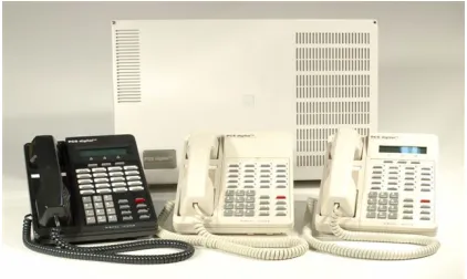
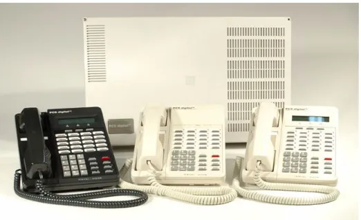
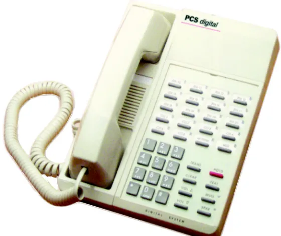
An illustration of the Suite64 cabinet and 2 Key Telephone Sets are shown below in Figure 1.
Figure 1-1 Suite64 Digital Hybrid Key Telephone System
The Suite 64 incorporates state‐of‐the‐art digital technology for voice switching and
call processing utilizing Pulse Code Modulation and Time Division Multiplexing (PCM/TDM).
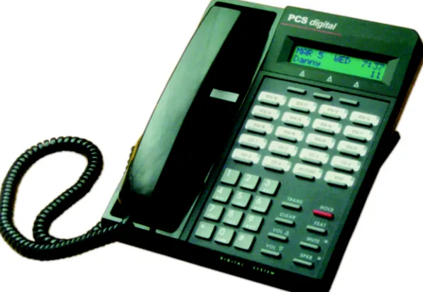
Suite 64 31-Button Model
The Suite 64 is a non‐blocking switch featuring no degradation of voice signals. The system utilizes a 16‐bit, 20 MHz main microprocessor and peripheral device (extensions and CO lines) processors in a distributed processing configuration. Memory consists of 640K bytes of ROM and 384K bytes of RAM.
The Suite 64 is shipped as follows:
• 1‐KSU with the following: ‐Ten (10) digital extension ports.
‐Two (2) analog device ports.
‐Six (6) CID ready CO Line ports.
‐ Two music source enters (can be assigned as desired to CO lines for hold music/messages.
‐ One power failure port (CO Line 1).
‐ One control contact (LBC, Gate, External Page Control).
‐ One external paging equipment interface.
‐ Two serial ports.
‐ PC‐RMP Programming Interface.
1-4
| Suite 16 Installation, Programming & Maintenance Manual | In tr oduc tion1
About this Manual
The Suite 64 Installation, Programming & Maintenance manual is divided into the
following sections:
• Section 1 ‐ Introduction ‐ this section provides a general description of the
Suite 64 system as well as a description of the manual contents, associated
documentation, and a listing of the document conventions.
• Section 2 ‐ System Design ‐ This section provides descriptions of the individ‐ ual components of the Suite 64 system.
• Section 3 ‐ Basic Programming ‐ This section provides basic instructions for accessing the Suite 64 programming database using both a 31‐Button Model Telephone and the RMP PC application.
• Section 4 ‐ Installation ‐ This section provides instructions for the installa‐ tion of the KSU cabinets and pin out information.
• Section 5 ‐ Phone Extension Programming (01) ‐ This section provides 31‐Button model telephone and RMP programming instructions for the Suite 64 features such as Auto‐Record, Call Forwarding, Class of Service Programming,
CO Line Assignments, Intrusion and others.
• Section 6 ‐ Phone Trunk Programming (02) ‐ This section provides 31‐Button model telephone and RMP programming instructions for the Suite 64 fea‐ tures such as Call Forwarding with Predefined CO Lines, CO Line Group Pro‐
gramming, CO Line Ring Assignments and others.
• Section 7 ‐ Phone Call Handling Programming (03) ‐ This section provides 31‐Button model telephone and RMP programming instructions for the Suite 64 features such as Alarm Clock‐Extension, Alarm Clock‐System, Answering
Machine Emulation, Auto Attendant and others.
• Section 8 ‐ Phone System Resource Handling (04) ‐ This section provides 31‐Button model telephone and RMP programming instructions for the Suite 64 features such as Attendant Programming, DSS Console Programming, Call
Operator‐Attendant, Extension Passwords and others.
• Section 9 ‐ Phone Restriction Programming (05) ‐ This section provides 31‐Button model telephone and RMP programming instructions for the Suite 64 features such as Account Code ‐ Voluntary/Forced/Verified, Toll Restric‐
tion‐COS and others.
• Section 10 ‐ Phone Trunk Application Programming (06) ‐ This section pro‐ vides 31‐Button model telephone and RMP programming instructions for
the Suite 64 features such as Voice Mail‐Digital Integration and others.
• Section 11 ‐ Phone Extension Application Programming (07) ‐This section provides 31‐Button model telephone and RMP programming instructions for the Suite 64 features such as CO Line Alternate Route, Fax Tone Detection and others.
• Section 12 ‐ Phone System Application Programming (08) ‐ This section pro‐ vides 31‐Button model telephone and RMP programming instructions for
the Suite 64 features such as 12/24‐Hour Mode Selection, Automatic CO Line
• Section 13 ‐ User Programming ‐ This section provides 31‐Button model tele‐ phone programming instructions for User Features such as Auto‐Hold, Auto‐
matic CO Line/Intercom Selection, Feature/DSS Button Programming, and others.
Descriptions of these features and others can also be found in the Suite 64 31‐Button Telephone User Guide.
• Section 14 ‐ Programming Quick‐Reference Charts ‐ This section provides quick reference charts for all of the 31‐Button model telephone programming instructions described in Section 5 through Section 12.
Document Conventions
The following conventions are used throughout this manual.
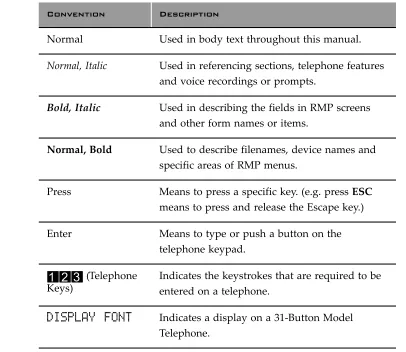
Table 1-1 Conventions
Convention Description
Normal Used in body text throughout this manual.
Normal, Italic Used in referencing sections, telephone features
and voice recordings or prompts.
Bold, Italic Used in describing the fields in RMP screens and other form names or items.
Normal, Bold Used to describe filenames, device names and
specific areas of RMP menus.
Press Means to press a specific key. (e.g. press ESC means to press and release the Escape key.)
Enter Means to type or push a button on the telephone keypad.
123
(Telephone Keys)1-6
| Suite 16 Installation, Programming & Maintenance Manual |In
tr
oduc
tion
1
Related Documents
The following documents should be used in conjunction with this manual:
• Suite 64 31‐Button Model Telephone User Guide
• Suite 64 28‐Button Model Telephone User Guide
• Suite 64 Flash Voicemail Installation & Maintenance Manual
1 Introduction ... 1.1
2 System Design... 2.1
2.1 Key Service Unit (KSU) . . . 1
2.2 Power Supply. . . 2
2.3 CCB (Common Control Board) . . . 3
2.4 610+2 (KSU1 Component) . . . 5
2.5 Base Board . . . 6
2.6 4SLT Board (Analog Port Module‐4 Circuits). . . 7
2.7 12EKT (Digital Port Module ‐ 12 Circuits) . . . 8
2.8 6CO Board (Central Office Module ‐ 6 Circuits) . . . 9
2.9 Modem Module. . . 10
2.10 4VAA Board (4‐Port Voice Automated Attendant) . . . 11
2.11 Digital Telepones. . . 12
2.13 28‐Button Telephone. . . 14
2.14 DSS (Direct Station Selection Terminal). . . 15
2.15 Expansion Boards . . . 15
2.16 System Limits/Capacities . . . 16
2.17 Configuration Flexibility . . . 22
3 Installation ... 3.1
3.1 Installation Outline . . . 13.2 Site Planning . . . 5
3.2 KSU Initialization Procedure. . . 17
3.3 Door Phone Installation . . . 18
3.4 Hardware Installation . . . 19
3.5 Programming. . . 22
4 Basic Programming... 4.1
4.1 General . . . 14.2 Accessing and Sending Modifications to the RMP . . . 8
TOC-2
| Suite 64 Installation and Maintenance Manual |
TC
5.15 Extension Programming (01) ... 5.1
5.1 Auto‐Record . . . . 1
5.2 Call Forward– Extension. . . . 4
5.3 Class of Service – Extension . . . . 8
5.4 CO Line Assignment . . . . 10
5.5 CO Line Receive Assignment. . . . 12
5.6 Extension Paging Groups . . . . 14
5.7 Extension Pick Up Groups . . . . 16
5.8 Extension Swapping . . . . 18
5.9 Feature Button Disable . . . . 20
5.10 Intrusion ‐ Extension/CO Line . . . . 22
5.11 Monitor‐Extension‐CO Line . . . . 24
5.12 Paging . . . . 26
5.13 Recorded Announcement Device . . . . 30
5.14 Station Message Detail Recording (SMDR) . . . . 33
5.15 Tenant Groups . . . . 37
5.16 UCD Voice Announce Group. . . . 42
5.17 Voice Call Recorder (via voicemail System). . . . 46
5.18 Voicemail – Analog Integration . . . . 48
5.19 Warning Tone / CO Line Call Limiter . . . . 58
6 Phone Trunk Programming (02) ... 6.1
6.1 Call Forward – CO Line Predefined (No Answer Condition). . . . 16.2 Class of Service – Extension . . . . 6
6.3 CO Line Group . . . . 8
6.4 CO Line Loop Supervision (Talk/Hold Abandon) . . . . 10
6.5 CO Line Ring Assignment (Answer Position) . . . . 13
6.6 CO Line Ring Type Assignment . . . . 15
6.7 CO Line Ringing Modes . . . . 17
6.8 CO Line Signaling / Dialing Type (Tone/Pulse). . . . 20
6.9 CO Line Type Assignment (Trunk Type) . . . . 22
6.10 Distinctive Ringing – CO Line . . . . 25
6.11 Music On Hold (Two Source) . . . . 27
6.12 Privacy Release. . . . 29
6.13 Private Line . . . . 31
7 Phone Call Handling Programming (03)... 7.1
7.1 Alarm Clock – Extension . . . . 17.2 Alarm Clock – System (System Reminder) . . . . 4
7.3 Answering Machine Emulation . . . . 6
7.4 Automated Attendant . . . . 8
7.5 Auto Redial . . . . 15
7.6 Call Forward – Extension . . . . 18
7.7 Call Forward – Extension Predefined . . . . 22
7.8 Caller Identification Table – Callback . . . . 26
7.10 Meet Me Conference. . . 33
7.11 Conference, Supervised/Unsupervised . . . 36
7.12 Direct Inward System Access (DISA). . . 41
7.13 End‐To‐End Signaling/Voicemail Dialing Ratio . . . 46
7.14 Flash – Analog Port (SLT) Flash Recognition . . . 48
7.15 Flash – CO Line . . . 51
7.16 Flash – PBX Line . . . 53
7.17 Hold – Hold Reminder, Common (System), I‐Hold Indication . . . 55
7.18 Exclusive Hold. . . 59
7.19 Hold Abandon. . . 61
7.20 Hotel Mode – Alarm Clock Extension . . . 63
7.21 Pause / Pause Insertion. . . 65
7.22 Single Line Telephone‐Flash . . . 68
7.23 Tone/Pulse/Inter‐Digit Duration Selection . . . 71
7.24 Transfer . . . 74
7.25 Warning Tone / CO Line Call Limiter . . . 77
8 Phone System Resource Handling (04) ... 8.1
8.1 Attendant . . . 18.2 Attendant / Extension DSS Console . . . 4
8.3 Attendant / Extension DSS Console Button Programming . . . 6
8.4 Call Operator / Attendant . . . 8
8.5 CO Line Name / Label Programming . . . 11
8.6 Direct Station Selection Console (DSS) . . . 14
8.7 Extension Password . . . 17
8.8 Extension User Name . . . 19
8.9 Loud Bell / External Page / Music Source – Control . . . 21
8.10 Messaging – Call Me, Text or Voice . . . 24
8.11 Messaging – Status Text . . . 26
8.12 Modem . . . 28
8.13 Remote RMP Programming Setup Parameters . . . 30
8.14 Speed Dialing – Extension/System . . . 34
TOC-4
| Suite 64 Installation and Maintenance Manual |
TC
11 Phone Extension Application Programming (07) ... 11.1
11.1 CO Line Alternate Route . . . . 1
11.2 FAX Tone Detection . . . . 5
11.3 PBX Compatibility . . . . 8
11.4 CO Line Group Directory Number Swapping . . . . 10
12 Phone System Application Programming (08)... 12.1
12.1 12/24‐Hour Mode Selection . . . . 112.2 System Time and Date . . . . 3
12.3 Automatic CO Line Ringing Modes . . . . 5
12.4 Call Pickup‐Group. . . . 8
12.5 CO Line Programming Copy . . . . 9
12.6 Extension Programming Copy. . . . 12
12.7 Ring Scheme . . . . 15
12.8 External Music Source (Two Standard). . . . 17
12.9 External Paging . . . . 19
12.10 Numbering Plan. . . . 21
13 User Programming ... 13.1
13.1 Alphanumeric Display (Super Twist) . . . . 113.2 Attendant Administration (Administration) . . . . 2
13.3 Auto Hold . . . . 7
13.4 Automatic Selection (CO/Intercom) . . . . 8
13.5 Auxiliary Lamp / LED Status Bar . . . . 9
13.6 Background Music (BGM) . . . . 11
13.7 Battery Back‐Up (Memory) . . . . 12
13.8 Battery Back‐Up (System). . . . 13
13.9 Busy Lamp Field – DSS . . . . 14
13.10 Busy Ring (Allow/Deny). . . . 15
13.11 Call Back – Cancel All . . . . 16
13.12 Call Back (CO Line) . . . . 17
13.13 Call Back (Extension). . . . 19
13.14 Call Duration Timer . . . . 21
13.15 Call Park/Call Park Answer . . . . 22
13.16 Caller ID . . . . 23
13.17 Caller ID Log . . . . 25
13.18 Camp On (Extension) . . . . 27
13.19 CO Line Calling & I‐Use Indication . . . . 28
13.20 CO Line Queuing / Callback . . . . 29
13.21 Default Extension. . . . 31
13.22 Dial Pad Confirmation / Touch Tone. . . . 32
13.23 Distinctive Ringing – Extension. . . . 33
13.24 Do Not Disturb. . . . 34
13.25 Do Not Disturb (One Time) . . . . 36
13.26 Do Not Disturb (Override) . . . . 37
13.28 Extension Password . . . 40
13.29 Feature/DSS Button Reset . . . 41
13.30 Directory/Feature/Suffix Code Lookup . . . 42
13.31 Feature/DSS button Inquiry. . . 43
13.32 Feature/DSS Button Programming. . . 44
13.33 Forced Intercom (Call Forward) . . . 46
13.34 Forced Intercom Tone Ring . . . 47
13.35 Hidden Codes . . . 48
13.36 Holding Call Answer . . . 50
13.37 Hot Key Enable/Disable . . . 51
13.38 Hot Line . . . 52
13.39 Making an Intercom Call . . . 54
13.40 Voice Announce. . . 55
13.41 Last Number Redial . . . 57
13.42 Meet Me Page . . . 59
13.43 Note Pad . . . 60
13.44 Mute . . . 61
13.45 Night Mode/Activate . . . 62
13.46 On‐Hook Dialing. . . 63
13.47 Voice Page (Allow/Deny) . . . 64
13.48 Phantom Lines / Virtual Numbers . . . 65
13.49 Phone Lock/Unlock. . . 67
13.50 Pulse to DTMF Conversion . . . 69
13.51 Recall. . . 70
13.52 Release Key . . . 71
13.53 Reminder Tones. . . 72
13.54 Ringing Level / Muted Ringing. . . 73
13.55 Ringing Line Priority . . . 74
13.56 Saved Number Redial. . . 75
13.57 Single Line Telephone – CO Line Flash . . . 76
13.58 Single Line Telephone / Analog Device Support . . . 77
13.59 Speakerphone . . . 79
13.60 Transfer and Answer Call . . . 80
13.61 UCD Agent Log Off/Log On . . . 81
13.62 UCD Overflow and Reroute . . . 82
TOC-6
| Suite 64 Installation and Maintenance Manual |
2
System Design
The Suite 64 Key Service Unit (KSU) is designed as a modularized, flat‐pack. Two
KSU’s (KSU1 and KSU2) may be equipped to attain the total system capacity of 24 CO lines, 58 Extensions (46 digital and 18 analog) and 8 Voice Processing
Channels. Each KSU is designed to be mounted on the wall and is shipped with a wall mounting template. The compact KSU weighs less than 20 pounds and is UL Listed.
If using 2 KSU’s, the first KSU, or KSU1 is factory equipped with one 610+2 Board, one CCB (Common Control Board). The second KSU or KSU2 is factory equipped with one Base Board module. Each KSU is a self‐contained cabinet containing an internal power supply for either 117vac or 230vac operation. At the time of shipping it is set for 117vac operation. From the exterior, with covers in place, KSU1 and KSU2 look identical, however, KSU1 contains the Common Control Board(CCB).
Figure 2-1 Suite 64
KSU
2-2
| Suite 64 Installation, Programming & Maintenance Manual |System
Design
2
The power supply circuitry of the Suite 64 incorporates a linear design AC
transformer with a choice of enter voltage taps. The transformer primary windings are shipped wired for 117vac applications. A factory provided switch alternates between 230vac and 117vac applications. The output voltage is delivered to the 610+2 Board(in KSU1, Base Board in KSU2) for voltage regulation. All system operation and logic voltages are produced at these boards.
Two fuses are provided on the power supply board; one for ac enter over‐voltage protection and one for DC output over‐current protection. A main power switch is accessible on the side of each KSU. In the event battery backup operation is desired the KSU power cord can be connected with an external (ancillary) UPS (Uninterruptible Power Supply). It is the responsibility of the installer to match the battery requirements/UPS requirement to the specific needs of the equipment owner.
The CCB module is equipped standard in KSU1. This board contains all circuitry required to control the fully equipped Suite 64. All digital voice switching and call processing data switching is accomplished via the CCB.
The CCB has one ribbon cable connector for connection to the KSU1 610+2 board and five (5) connector sockets for connection of the system built‐in modem, voice processor and 2nd Cabinet (KSU2). Since the CCB comes installed inside of KSU1 the CCB ribbon cable is already in place and connected to the KSU1‐610+2. Assuming the orientation of the KSU1 cabinet is installed on the wall; the two horizontal connector sockets in the lower left corner of the CCB are for the Modem Module. The connector socket labeled “2nd Cabinet” is for connection to the KSU2‐Base Board if that expansion is required. The remaining two connector sockets on the CCB, one at the left side, the other at the right side are for the voice processor solution. (The voice processor solution can be any of three possible choices; 4VAA, Flash Voicemail or HD Voicemail.)
2-4
| Suite 64 Installation, Programming & Maintenance Manual |System
Design
2
The CCB also provides the following standard connectors:
• Music Channel 1 ‐ On Hold/Background Music Interface • Music Channel 2 ‐ On Hold/Background Music Interface • Control Contact (Loud Bell or External Page Relay) • External Paging Equipment Interface
• RMP Serial Port ‐ for on‐site database programming
• SMDR Serial Port ‐ for connection to ancillary SMDR/Call Accounting equip‐ ment
The CCB has two Option Strap jumpers one for database start‐up (J7) and one for Music Channel One source (internal/external) selection (JP81).
• JP7 Cold Start/Normal : JP7 is used to force load database default factory settings. This jumper will normally never require operation after the initial power up sequence is completed. However should the need arise to return the site database to the factory settings this jumper is used to accomplish the task.
• JP81 Internal/External: J81 is used to select the Music Channel 1 source. The
Suite 64 provides a synthesized music source for music on hold in applica‐
tions where no music source is available. The synthesized tune is repeated. JP7 is in the “External” position when it ships from the factory.
The 610+2 is the large circuit board that is packaged inside of KSU1. The 610+2 provides interface for up to 6 loop‐start CO Lines, 10 Digital Extension Ports and 2 analog ports. Additionally the 610+2 regulates the 24 volt DC power from the source to produce all required logic voltages and operations voltages. There is also a Power Failure Port located on the 610+2 that is connected to the first CO Line circuit. Whenever power fails this port becomes active with dial tone from the CO line connected to the first CO line port.
Each CO line circuit on the 610+2 board incorporates over‐voltage protection, ring detector, loop detector, loop/pulse‐dial relay, current sink circuit, coupling/isolation transformer (impedance 600:600), hybrid circuit, CODEC & filter, polarity guard circuit and Radio Frequency noise filter.
The sixth CO Line port is equipped with CNG Fax Tone Detection circuitry. If FAX tone is detected, the call is routed to the analog port designated as the destination for fax calls.
Each digital port (connects to 31‐Button & 28‐Button Telephones and DSS
Consoles) is comprised of a proprietary octal ASIC (Application Specific Integrated Circuit) transceiver. There are three data channels in operation at each digital port via the octal transceiver. One channel is used for call processing control of digital terminal functions/operations and two channels are used for the digital voice channel requirements.
Each digital station interface is protected against circuit wiring shorts by an over‐current protection Polyswitch. The digital station circuit requires only one cable pair to operate and is not polarity sensitive.
Physical connection of digital extensions, power failure telephones and CO lines to the 610+2 board is made through a 25 pair amphenol connector to be terminated on the MDF. (Main Distribution Frame)
2-6
| Suite 64 Installation, Programming & Maintenance Manual |System
Design
2
The Base Board is unique to KSU2. It provides connecitivity with peripheral boards. Additionally the Base Board regulates the 24 volt DC power from the source to produce all required logic voltages and operations voltages.
The KSU2 operation LED (located next to the power switch) is tied to the CCB (KSU1) LED. Therefore, when the LED next to the power switch is flashing, the CCB (KSU1) is active.
A long shielded cable is used to connect KSU2 to the CCCB inside of KSU1.
Each digital station interface is protected against circuit wiring shorts by an over‐current protection Polyswitch. The digital station circuit requires only one cable pair to operate and is not polarity sensitive.
The 4SLT Board provides four separate analog device ports. This allows the Suite 64 to support auxiliary office equipment found on the business premises such as fax machines, PC/Mac modems and analog telephones (single line telephones). The 4SLT Board generates ‐30VDC and 20‐25Hz, 50V square wave ringing for
operation.
The 4SLT Board is equipped with a Heartbeat LED that indicates processing activity on the PCB. (The 4SLT Board peripheral processor is operating when the Heartbeat LED is flashing.)
The 4SLT Board provides DTMF receivers for each analog port. Ancillary analog devices connected to 4SLT analog ports must generate DTMF signaling. (Pulse dial (rotary‐dial) telephones/equipment are not supported.) All connections are via RJ‐11 connectors along the top edge of the module.
Up to 2‐ 4SLT Boards may be installed on 610+2 Board and up to 2 on the Base Board.
2-8
| Suite 64 Installation, Programming & Maintenance Manual |System
Design
2
The 12EKT module expands the Suite 64 system capacity of digital ports 31‐Button & 28‐Button Telephones and DSS Consoles. Each digital port is comprised of a proprietary octal ASIC (Application Specific Integrated Circuit) transceiver. There are three data channels in operation at each digital port via the octal transceiver. One channel is used for call processing control of digital terminal
functions/operations and two channels are used for the digital voice channel requirements. The 12EKT is controlled directly from the 610+2 Board/Base Board.
Each digital station interface is protected against circuit wiring shorts by an over‐current protection Polyswitch. The digital station circuit requires only one cable pair to operate and is not polarity sensitive.
Physical connection of digital port terminals (31‐Button & 28‐Button Telephone and DSS) to the 12EKT module is made through a 25‐pair amphenol connector along the top edge of the module.
1 Additional 12EKT module can be added to KSU1 and 2 in KSU2.
The 6CO Board is installed in the dedicated position of the 610+2 Board/Base Board. The 6CO interfaces 6 loopstart CO (Central Office [Telephone Company]) lines. One 6CO Board is installed in KSU1. An additional 6CO Board can be added for a total of 12 loopstart CO lines. Two 6CO Boards may be installed in KSU2. Therefore, the Suite 64 system CO line capacity may be expanded to interface 24 total loopstart CO lines.
The 6CO module is shipped with four (4) mounting stand‐offs used to install the board into the KSU1 or KSU2.
Each CO line circuit incorporates over‐voltage protection, ring detector, loop detector, loop/pulse‐dial relay, current sink circuit, coupling/isolation transformer (impedance 600:600), hybrid circuit, CODEC & filter, polarity guard circuit and Radio Frequency noise filter.
The sixth CO Line port is equipped with CNG Fax Tone Detection circuitry. When programmed as a “FAX” line, this circuit will automatically engage the FAX Tone detector. If FAX tone is detected, the call is routed to the analog port designated as the destination for fax calls.
2-10
| Suite 64 Installation, Programming & Maintenance Manual |System
Design
2
The Modem Module is a self‐contained integrated modem unit that is installed at J5 and J6 in the lower left corner of the CCB. The integrated Modem Module allows the servicing Interconnect Company to access the telephone system
programming and remote maintenance utilities from an off‐site location (password verification required).
When installed, the servicing technician uses the Remote Maintenance &
Programming software (RMP) and a modem (in the PC) to place a call to the site where the Suite 64 is installed. If one of the voice processing systems are installed, routing to the modem extension is automated. Otherwise the person who
answered this data call must transfer the call to Extension 400 (Default). Once the modems have established the data connection, RMP may be used to perform all servicing operations.
The Automated Attendant Module is a self contained integrated module that adds automatic answering of selected CO lines and a single‐level menu for greeting callers and routing them to Suite 64 system destinations. The 4VAA is a wonderful low cost voice processing system that can handle all call traffic or act as a backup to the primary answering system attendant.
The 4VAA is installed at J3 and J4 of the CCB.
The 4VAA provides 10 greetings for the various modes of system/action operation. They are: Day Greeting, Alt Greeting, Night Greeting, Waiting Message, Invalid Message, Busy Message, No Answer Message, Goodbye Message, Inquiry Message and Temporary Message.
2-12
| Suite 64 Installation, Programming & Maintenance Manual |System
Design
2
The Suite 64 has 4 different model telephones. The 31‐Button telephone comes
with a display and three soft buttons, in either charcoal or off‐white, and the 28‐button telephone has no display, or soft buttons, in either charcoal or off‐white. Both Telephones come equipped with a half‐duplex speakerphone for hands‐free conversations . The 31‐button telephone has a two‐row by sixteen column
(32‐character), dot‐matrix, Super Twist, Liquid Crystal Display (LCD). Directly under the LCD are three Interactive Buttons to enhance system features operation. During the various features operations these Interactive Buttons take‐on functions to aid in feature use.
The Super Twist LCD eliminates the need for contrast adjustment and enhances angled viewing position clarity of displayed data. Since the Suite 64 includes Caller ID as a standard feature, the LCD also enables every designated ringing extension to receive Caller Identification* data for incoming CO line calls.
This feature requires a subscription from the servicing telephone company.
The display provides a visual reference to call progress and call duration, as well as time and date information. The display also enables the user to send and receive visual advisory and callback messages. Users may select from six “canned” messages (i.e., “IN A MEETING,” “OUT OF OFFICE”), or they may create a custom message. Calls from other Suite 64 telephone users to an extension with a message active will receive the visual advisory message on their LCD display.
Each 31‐Button Telephone has twenty (20) Programmable Feature Buttons to aid the user by providing direct access to system features and resources. There are also three (3) Interactive Buttons and 8 fixed function buttons.
Figure 2-9 31-Button Model Telephone and default button layout
INSERT THE PCS DIGITAL TELEPHONES
E x t . 4 0 1 E x t . 4 0 2 E x t . 4 0 3 E x t . 4 0 4 E x t . 4 0 5 E x t . 4 0 6 E x t . 4 0 7 E x t . 4 0 8 E x t . 4 0 9 E x t . 4 1 0 E x t . 4 1 1 E x t . 4 1 2 L I N E 1 L I N E 2 L I N E 3 L I N E 4 L I N E 5 L I N E 6 A n n o u n c e F 9 8 V O I C E M W F 6 4
F I X E D K E Y S
2-14
| Suite 64 Installation, Programming & Maintenance Manual |System
Design
2
The 28‐Button Telephone features twenty (20) programmable Feature/DSS
buttons (dual color LED), 8 fixed feature keys (Mute, Speaker, Hold, Transfer, Clear, Feature, Volume Up, Volume Down).
Figure 2-10 Suite 64 28-Button Model Telephone and default button layout
2.13
28-Button Telephone
Ext. 401 Ext. 402 Ext. 403 Ext. 404 Ext. 405 Ext. 406 Ext. 407 Ext. 408 Ext. 409 Ext. 410 Ext. 411 Ext. 412 LINE 1 LINE 2 LINE 3 LINE 4 LINE 5 LINE 6 Announce F98 VOICE MW F64
FIXED KEYS TRANS HOLD
CLEAR FEAT VOL UP MUTE [*]
The DSS Console is a digitally interfaced component of the Suite 64. It connects to the system via any available digital port (610+2 Board/E or 12EKT digital port). The DSS is equipped with 50 Programmable Buttons. 48 buttons are equipped with dual color (red / green) LEDs and 2 are red only. Any of these buttons may be assigned as a system Feature Code or Directory Number. (These buttons may be assigned for either system features operations or CO line access operations.)
The DSS Console may be mounted in three positions (Low Profile, Desk Position and Wall Mounted Position). DSS Consoles are programmed to operate with an associated speakerphone. Speakerphones may be assigned up to 4 DSS Consoles each if required. The maximum DSS Consoles supported by the Suite 64 is 12. Each equipped DSS Console requires one digital port therefore the total number (system capacity) of speakerphones possible is reduced by one for each DSS console installed.
Integrated voicemail (IVM) Board ‐ Includes 8 channels with up to 120 hours of voicemail recording time. It will be available as both Hard Disk and Flash‐based.
T1 PRI Board ‐ [Future Feature]
VoIP Gateway Board ‐ [Future Feature]
2.14
DSS (Direct Station Selection Terminal)
2-16
| Suite 64 Installation, Programming & Maintenance Manual |System
Design
2
Time Slots:
PCM ‐ 32 time slots x 4 Highways (128 voice channels) TDM 64 Time Slots (data processing) Customer Database memory protection 300 hours via on‐board lithium battery (no charging required)
Ports:
CO/PBX/Centrex Lines: ‐ 24
Digital Stations: ‐ 46
Standard Single Line Telephones: ‐ 18
DTMF Receivers: One dedicated per single line telephone port.
DTMF Senders: Unlimited. (DTMF signal generation is derived from the core system tone resource. Tone combinations are available as needed.)
Contacts: 1 LBC can be programmed as associated to a CO line, Music on Hold, or Paging or dialed by an extension to actuate the contact.
Conference circuits: 8 ‐ 4 party conference circuits.
DISA circuits: Any number of CO lines may be programmed for DISA operation. (4VAA required for operation.)
System Attendants: 1 Attendant + 1 Alternate per Tenant Group
Tenant Groups: 3
UCD/Hunt Groups: 24
Members per Group: 24
Group Types: UCD or Voice Announcer
Hunting Method: Linear, All Ring or Distributed
Voicemail Groups: 1 per Tenant (uses 1 UCD Group per VM system)
Members (ports): 24
Integration Method: Digital Integrated Voice Systems and In‐band (for others)
VM Message Waiting:
#96
+ station number to turn VM button LED on.VM Control codes:
#*96
+ station number to turn VM button LED off.Disconnect Digit(s): 8 digits max.
Subscriber Calling via Intercom: 4 digits max.
Transfers to VM : 4 digits max.
Busy Forward: 4 digits max.
No Answer Forward: 4 digits max.
Direct Call Forward: 4 digits max.
CO Line Recall: 4 digits max.
CO Line Ringing: 4 digits max.
UCD Overflow: 4 digits max.
Record Digits for Voice Recorder function: 4 max.
Delete Digits: 4 digits max.
Suffix for transferred calls: 2 max.
CO Line Loop Current sensing: Interrupt programmable from 50ms to 2500ms.
Paging: 8 Internal Page Extension Groups; 1 External Page Port; 1 Internal All Call; 1 System (Internal/External) All Call;
Speed Dialing: 1000 total bins, dynamically allocated.
200 bins at default allocated for system‐wide use.
20 bins at default allocated for extension use (extensions 401‐446 only) (50 possible per extension)
16 digits maximum per bin.
Last Number Redial: 16 digits per station
2-18
| Suite 64 Installation, Programming & Maintenance Manual |System
Design
2
Message Waiting: 40 simultaneous maximum per system (does not affect VM message indications)
Name in Display: 1 per station, 7 characters max.
Class Of Service (COS): 10 (0‐9) per Day, 10 (0‐9) per Night
Toll Restriction To/From Tables: 100 Tables per tenant, 10 digits per entry, Day and Evening COS assignable per entry per CO Line and Extension.
Forced Verified Account Codes: 600 codes, 2‐8 digits max., each assigned a COS.
Call Pick Up Groups: 8 Extension Groups.
Station Lock Password: 4‐8 digits per extension.
DB Programming Password: 8 digits (“________” at default).
System Reminder Alarm: 8 time settings per Tenant Group.
Station Alarm: 1 per station repeating or one time.
Ring Schemes: 8
Distinctive Ring Tones: 8 per station.
Electrical Specifications
AC Power Source: Dedicated 117/230vac + 15%, 47‐63Hz single phase
Power consumption: 1.5A maximum @ 120vac (180 watts)
Power Supply Fuse:
AC enter: 2A 250v
DC output: 1A 125v
Idle Channel Noise: ‐74 dB
Cross Talk Attenuation: 75 dB (@ 1kHz)
Ringing Sensitivity: 40v RMS 25 Hz
Ringer Equivalence Number: 1.5
CO Line Signaling: DTMF amplitude (‐5 dB,‐7 dB) +‐ 2 dB, @ approx. 2 Vpp
Pulse Dialing ratio 60/40 @ 10 PPS
Music source / Background Music: 0 dBm at 600 ohm enter impedance; 1/8th inch phono jack
Contact rating (Option Module LBC): 1A @ 30VDC; 0.5A @ 90VAC 30Hz; 1/8th inch phono jack
External Page Port: 0 dBm at 600 ohms; 1/8th inch phono jack
Environmental Data
Operating Temperature: 0o to 40o C, 32o to 95o F
Recommended Operating Temperature: 70o to 78o F
2-20
| Suite 64 Installation, Programming & Maintenance Manual |System
Design
2
Wiring Data
31‐Button & 28‐Button Telephones (Distance measures in linear feet of cable
from KSU to phone):
26 AWG ‐ 650 ft. (195m)
24 AWG ‐ 1133 ft. (340m)
22 AWG ‐ 1586 ft. (476m)
Standard Single Line Telephone (Distance measures in linear feet of cable
from KSU to SLT):
26 AWG ‐ 850 ft. (255m)
24 AWG ‐ 1416 ft. (425m)
22 AWG ‐ 1983 ft. (700m)
Signaling Data
DTMF Dialing mode:
Frequency deviation: + 1%
Rise time: 3ms
Duration of DTMF signal: programmable 50‐150ms (70ms default)
Inter‐digit time: programmable 50‐150ms (70ms default)
VM Port DTMF duration: programmable 60‐150ms (120ms default)
VM Port Inter‐digit time: programmable 60‐150ms (120ms default)
Pulse Dialing mode:
Pulse dial rate: 10 pulses per second
Internal Audible Signals
Frequency Cadence
CO Line Ringing:
Scheme 0 N/A 300ms On, 400ms Off, 300ms On, 4 seconds Off Scheme 1 N/A 1 second On, 3 seconds Off
Scheme 2 N/A 1 second On, 3 seconds Off
Scheme 3 follows ring cadence of Ring Scheme selected Scheme 4 follows ring cadence of Ring Scheme selected Scheme 5 follows ring cadence of Ring Scheme selected
Scheme 6 follows ring cadence of Ring Scheme selected Scheme 7 SLT bell follows ring cadence of Ring Scheme selected Distinctive 1
Distinctive 2 Distinctive 3 Distinctive 4 SLT
Frequency Cadence
Intercom Ringing:
Scheme 0 N/A 1 second On, 3 seconds Off Scheme 1 N/A 1 second On, 3 seconds Off
Scheme 2 N/A 300ms On, 400ms Off, 300ms On, 4 seconds Off
Scheme 3 follows ring cadence of Ring Scheme selected Scheme 4 follows ring cadence of Ring Scheme selected Scheme 5 follows ring cadence of Ring Scheme selected
2-22
| Suite 64 Installation, Programming & Maintenance Manual |System
Design
2
The Suite 64 can be configured with single or dual cabinets.
• Minimum (612): 6 CO lines + 10 digital +2 analog stations (single cabinet) • Maximum (1232): 12 CO lines + 22 stations + 10 SLT (single cabinet)
...or (1628): 12 CO lines + 4VoIP channels + 22 stations + 6 SLT (single cabinet)
• Growth with second cabinet: can be expanded to (1840), including 18 CO lines + 22 stations + 18SLT...
...or (2464), including 24 CO lines + 46 stations + 18SLT
...or (2852), including 24 CO lines + 4 VoIP channels + 46 stations + 6 SLT
...or (4052), including 12 CO lines + 24 T1/PRI channels + 4 VoIP channels + 46 stations + 6 SLT Only one VoIP gateway is allowed in cabinet 1.
• Only one 6CO board installation is allowed when T1/PRI is equipped in 2nd Cabinet.
The following combinations with different configurations can be generated:
1. First cabinet ‐ Maximum: equipped with 7 boards (including VAA/IVM on CCB) CCB + (610+2)(6CO+10EKT+2SLT) + 6CO + 12EKT + 4SLT + 4SLT + VoIP gateway .
Possible configurations for cabinet‐1 are shown below.
Table 2-1 Cabinet-1 Configurations
Configuration (CO/Extension)
MSU 612,i.e.
6CO, 10EKT,
2SLT)
6CO Board (6CO)
12EKT Board (12EKT)
4SLT Board
(4SLT) VoIP Gateway (4 Channels)
612 (Default) 1
616 1 1
620 1 2
624 1 1
628 1 1 1
632 1 1 2
1212 1 1
1216 1 1 1
1220 1 1 2
1224 1 1 1
1228 1 1 1 1
1232 1 1 1 2
1012 1 1
1016 1 1 1
1020 1 2 1
1024 1 1 1
1028 1 1 1 1
2-24
| Suite 64 Installation, Programming & Maintenance Manual |System
Design
2
The Flash Voicemail board can be substituted for the VAA card on the CCB for more user-friendly call administration.
VoIP Gateway (future feature) provides four more ports for the user to make VoIP calls through the Internet simultaneously. The T1/PRI (future feature) will increase the total number of Central Office Lines by 24.
2. Second Cabinet ‐ Maximum: equipped to use 6 boards (base board is included by default for PCB interconnection).
Base + 6CO + 12EKT + 6CO + 12EKT
...or Base + 6CO + 12EKT + 6CO + 12 EKT + 4SLT + 4SLT
...or Base + T1/PRI + 12EKT + 12EKT
...or Base + T1/PRI + 6CO + 12EKT + 12EKT
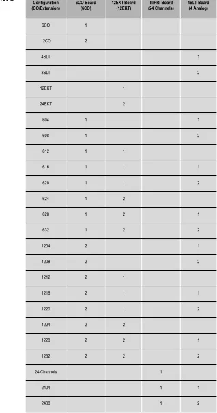
Possible configurations for cabinet‐2 are shown below.
Table 2-2 Cabinet-2
Configurations (CO/Extension) Configuration 6CO Board (6CO) 12EKT Board (12EKT) (24 Channels)TI/PRI Board 4SLT Board (4 Analog)
6CO 1
12CO 2
4SLT 1
8SLT 2
12EKT 1
24EKT 2
604 1 1
608 1 2
612 1 1
616 1 1 1
620 1 1 2
624 1 2
628 1 2 1
632 1 2 2
1204 2 1
1208 2 2
1212 2 1
1216 2 1 1
2-26
| Suite 64 Installation, Programming & Maintenance Manual |System
Design
2
2412 1 1
2416 1 1 1
2420 1 1 2
2424 2 1
2428 2 1
2432 2 2
3004 1 1
3008 1 2
3012 1 1
3016 1 1 1
3020 1 1 2
3024 1 2
3028 1 2 1
3032 1 2 2
Configuration
3
Installation
Optimum system operation and the best overall experience for the users of the
Suite 64 telephone system is assured when the following installation guidelines are
followed. Doing so will streamline the process and reduce or eliminate the potential of experiencing problems while bringing the Suite 64 on‐line.
1. Plan the installation, including the Key Service Unit (KSU1 & KSU2) and Main Distribution Frame (MDF) location, MDF, Electronic Key Telephone (EKT) station locations, Direct Station Selection (DSS) console locations, station cable runs, and optional equipment.
2. Prepare the correct tools and supplies. (UTP telephony grade cable/wiring. Miscellaneous telephony hardware; 66M1‐50 blocks, modular jacks, etc.)
3. Run Suite 64 extension cable/wiring for EKT, DSS consoles and analog devices (FAX machines, modems, etc.) from the MDF to each location. (Wiring topology is referred to as “star‐wiring” or “home‐run”
configuration; no cable should loop from one telephone location to another.)
4. Run cable/wiring to any optional equipment, such as external paging equipment, loud bell signaling devices, music sources, etc.
5. Mount the MDF backboard and attach the “punch‐down” (66) terminal block(s) on the backboard. This documentation adheres to traditional installation practices of telephony equipment using a dedicated MDF with
3-2
| Suite 64 Installation, Programming & Maintenance Manual |In
stallation
3
10. Install optional feature boards (4VAA or Voicemail Board ) inside KSU1 as required.
11. Route 25‐pair, Unshielded Twisted Pair (UTP) telephone grade cable through the appropriate KSU opening for EKT and CO line port interface connections.
12. Route ancillary device cabling through the appropriate KSU opening and terminate as required (music source, printer/computer for Remote
Maintenance and Programming (RMP), Station Message Detailed Recording (SMDR), external paging equipment, analog devices, door phones etc.).
13. Using single‐pair Cross‐Connect (jumper wire); connect the various port terminations of the KSU(s) from the Suite 64 66M1‐50 blocks to the USOC termination point for CO lines to be connected to the system and station cables for extensions to be connected to the system.
Whenever possible use of Bridging Clips are recommended for the connection of CO Lines. This allows the individual Central Office (CO) circuits to be disconnected for servicing while not affecting the other CO resources of the system. Therefore, it is recommend that a RJ21-X is ordered for USOC termination of CO Lines. This provides a convenient point of interface and location for bridging clips.
Using Bridging Clips on station port wiring is not recommended since this introduces a connection point that is not required. Service for any one extension can be actuated via the jumper wire of that extension without affecting any other station/extension ports/EKTs.
14. Install the terminal instruments (EKTs and DSSs) and any optional terminal equipment, such as Door Phones or analog devices.
Note
15. Locate the Cold Start/Normal option strap on the CCB Board inside KSU1. Move the Cold‐Start/Normal (RAM memory battery backup) strap from the factory set “Cold Start” position to the “Normal” position. This critical step is detailed again in the “Power Up Initialization” topic at the end of this chapter.
16. Plug the AC power cord into the dedicated AC outlet and power up the
Suite 64 system by operating the AC power switch to the “ON” position.
3-4
| Suite 64 Installation, Programming & Maintenance Manual |In
stallation
3
17. Observe the System Status LED on each KSU next to the power switch. This LED follows LED DA2 on the CCB (Central Control Board) and indicates the status of the main system processor. During the first
power‐up sequence (Cold‐Start strap moved to “Normal” position), default data (factory program) is loaded. A series of flash rates occur during this process. When default is successfully loaded or whenever the system becomes functional following a power failure, the CCB Heart‐beat LED and System Status LED maintains a consistent fast flash rate.
Establishing Suitable Environmental Conditions for the System
Place KSU1 (and KSU2 if applicable) within 5 feet (1.5 meters) of an isolated, dedicated, 105‐225VAC, 57‐63Hz, 15A, single‐phase commercial power source.
This must be an isolated, dedicated AC circuit for proper operation. All three wires (power, neutral, and ground) must be run separately from the outlet to the breaker panel without being bonded to any other wire or circuit. Do not plug any other equipment into this outlet. To maintain the protection provided by the isolated, dedicated circuit, the length of the AC power cord limits the distance between the KSU and the outlet. Do not use an extension cord.
To protect the system from lightning damage or other AC power line disturbances, a surge protector should be installed.
Select the KSU location to minimize cable run length. Terminal Equipment connected to the system must not exceed specified limits (see Specifications).
The location selected should not expose the KSU to direct sunlight, high humidity, heat, dust, or strong magnetic fields (such as those generated by heavy motors, copy machines and some kitchen appliances).
The Suite 64 system must be installed in a climate controlled environment.
When equipped with optional voice processing equipment, the system takes on the characteristics of a mechanically driven computing storage device. (A computer with a hard disk drive.)
3-6
| Suite 64 Installation, Programming & Maintenance Manual | In stallation3
SMDR/SMDA output device(s) must be placed within 50 feet (15 meters) of the KSU (limited by RS‐232C standard wiring practices). The computing equipment should be located in a climate‐controlled room adhering to the Environmental Specifications (see: “Specifications”).When installing the KSU and station instruments, allow a sufficient margin for error in case of air conditioning failure, routine maintenance, plant shutdown, etc. As a general rule, if conditions are suitable for office personnel, they are also suitable for the KSU computing device and terminal equipment
operation. A properly controlled environment will help to extend the operating life of the equipment.
Product Safety Specification Governing Telephone Equipment - UL 1459
• Never install telephone wiring during a lightning storm. • Never install telephone jacks in wet locations unless the jack is specifically designed for wet locations. • Never touch non‐insulated telephone wires or terminals unless the tele‐ phone line has been disconnected at the network’s interface. • Use caution when installing or modifying telephone lines.
Tools and Supplies
Preparing the Main Distribution Frame
The Main Distribution Frame (MDF) is the point at which the KSU, terminal equipment, CO lines, and miscellaneous equipment are connected to one another. It is extremely important that the connections be made carefully and accurately. The MDF is where the KSU is located.
Assembling the MDF
Follow these steps to assemble the MDF.
1. Mount a sufficiently sized 3/4‐inch plywood TMB (Telephone Mounting Board) at the proper location for use as the MDF termination and equipment mounting board.
2. Plan the layout of all required MDF components allowing for expansion. This may include: KSU1, KSU2, 66Ml‐50 termination blocks, cable fastening hardware, and miscellaneous third‐party communications equipment (paging equipment, etc.).
3. Locate the Telco provided CO/Centrex lines at the DEMARC (Demarcation) and extend them to the MDF location.
4. Locate a suitable, known‐good earth ground preferably within 10 feet of the MDF and route a #10 AWG grounding wiring from the point of grounding to the MDF for connection to the KSU. (See photo example.)
Install all terminal device wiring (telephone cabling) and route to the MDF location for termination.
5. Mount all equipment and termination hardware as required to complete interconnection of terminal devices and KSU ports.
KSU Components and Installation
The Key Service Units (KSU) are shipped in their own protective master carton and contain the following components:
3-8
| Suite 64 Installation, Programming & Maintenance Manual |In
stallation
3
KSU2
• 1 mounting template
• 1 Expansion Cabinet equipped with Base Board • 1 hardware packet
Open the carton(s) and verify that all items are complete and undamaged. Remove all packing material and store for future use in the event that return shipment is required.
Mounting the KSU
Follow these instructions to mount the KSU.
2. Using the mounting template as a guide, mark the two (2) mounting screws locations on the TMB for he mounting position preferred.
3-10
| Suite 64 Installation, Programming & Maintenance Manual |In
stallation
3
4. Lift the KSU over the two screws allowing the screws to extend into the
KSU slotted mounting holes. As the KSU is allowed to rest in place on the mounting screws it will slip over the screw shanks until the top of the slot is reached. Properly installed, the KSU cover will swing open to the bottom or to the right side depending on horizontal or vertical mounting. Appropriate spacing should be considered for the swing of the cover such that it can be opened sufficiently to perform work inside the cabinet.
It is very important that the KSU be correctly mounted to allow proper power supply heat dissipation. KSUI and KSU2 are intended to be wall mounted only. Mount each KSU using the slotted mounting holes as they were intended to assure compliance with this important heat-dissipation requirement.
Ground the KSU.
• Cold water pipe ‐ where the pipe is known not to have plastic or PVC insula‐ tors in‐line.
• Ground Rod ‐ where the grounding rod is known to meet local electrical specifications for grounding rod installation. The grounding rod in the photo is 2.5m (10ft) long.
Battery Connections (System Battery Back Up)
Connection of an external battery back up source is optional. Use the chart of Power Consumption of Components Installed in the “Specifications” section to determine the required battery supply necessary to maintain system functionality for the duration desired at this site. Use the following to install System Back‐Up Batteries:
The battery charging board is mounted at the Power Supply voltage regulator
Danger of explosion if battery is incorrectly replaced!
3-12
| Suite 64 Installation, Programming & Maintenance Manual |In
stallation
3
MDF (Main Distribution Frame)
The various ports of the Suite 64 are extended to the MDF using industry standard 4, 12, and 25 pair UTP (Unshielded Twisted Pair) cable. Inside the KSU pairs are terminated using screw terminal posts, modular ended crimping connectors and AMP‐type Male gender connectors. These cables are then routed out of the KSU to the 66M1‐50 blocks for termination and jumper‐wiring there. The installer has choices when completing these connections and it is left to the installer’s discretion to use the most suitable industry standard wiring practice for the particular installation. In the examples of this manual, standard 66M1‐50 connectors are used. The following example illustrates a two‐cabinet installation with the KSUs mounted vertically and side by side.
When routing cables to the appropriate connector in the KSU the Removable Access Panel can be temporarily removed to allow easy access to the various KSU connections.
Important! Replace the Removable Access Panel after all connections have been made. The panel is required to be in position to comply with FCC regulations.
The 66Ml‐50 is split into a left half and right half for wiring terminations.
Each row is conductive between the left two columns and the right two columns. This is the source of the term “Split 50.”
3-14
| Suite 64 Installation, Programming & Maintenance Manual |In
stallation
3
66M1-50 Pinouts
Suite 64 boards equipped with 25 pair AMP‐type cable connectors are:
• KSU1 6x10 + 2 Board • 12EKT
• KSU2 Base Board
3-16
| Suite 64 Installation, Programming & Maintenance Manual |In
stallation
3
1. Verify that the KSU power is OFF.
2. Verify that the jumper pins on JP7 are in the ʺColdʺ position.
3. Power up the KSU and wait 10 seconds.
4. Power down the KSU and move the JP7 pins to the ʺNormalʺ position.
3-18
| Suite 64 Installation, Programming & Maintenance Manual |In
stallation
3
6. Verify that the telephones have been initialized. A date/time display will be visible on the 31‐Button Telephones. For a 28‐Button telephone, a dial tone will be heard.
7. Enter the RMP programming mode and select RP, Remote Control, and perform a Software Cold Start. It should be approximately 30 seconds before a display is visible on the 31‐Button Telephones or a Dial Tone is heard on a 28‐Button Telephone.
8. When a display is visible on the 31‐Button Telephones or a Dial Tone is heard on a 28‐Button Telephone, power down the KSU, wait 15 seconds, and then power up the KSU again.
Description
The Suite 64 system permits 2 Door Phone extensions to be connected with the
610+2 Board. The extensions are analog and are used to activate relays which are connected with the on‐site door opening circuit or ancillary device.
Telephone keys can be programmed using either the 31‐ButtonTelephone or the RMP to open the door and set the unlocked time.
Up to 6 extensions per door phone can be programmed to ring when the door phone is activated.
Instllation of the Suite 64 Door Phone consists fo the following:
1. Connection with the 610+2 Board.
2. Connection of the door phone to the Suite 64 KSU.
3. Installation of the Mounting Bracket and mounting of the Door Phone.
4. Connection of the door phone and relays.
4. 31‐ButtonTelephone Programming or RMP Programming.