Design, Analysis and Optimization of I.C.
Engine Connecting Rod ALFASiC Material
Using Finite Element Analysis
Arun Raj.K.S1, Prakasam.N1, Natraj.R2, Aravindh.K3
Final Year Student, Department of Mechanical Engineering, Saranathan College of Engineering,
Trichirapalli, Tamilnadu, India 1
Pre-Final Year Student, Department of Mechanical Engineering, Saranathan College of Engineering,
Trichirapalli, Tamilnadu, India 2
Final Year Student, Department of Mechanical Engineering, SASTRA College, Thanjavur, Tamilnadu, India .3
ABSTRACT: Connecting rod is the intermediate link between the piston and the crank. And is responsible totransmit
the push and pull from the piston pin to crank pin, thus converting the reciprocating motion of the piston to rotary motion of the crank. Generally connecting rods are manufactured using carbon steel and in recent days aluminium alloys are finding its application in connecting rod. In this work the connecting rod material is replaced by aluminium based composite material reinforced with silicon carbide and fly ash (ALFASiC). For present investigation the designed connecting rod is modeled using solid modeling software i.e. PRO/E. The modeled connecting rod imported to the analysis software i.e. ANSYS. Finite Element Analysis are carried out by considering two materials (Forged Steel and ALFASiC). The parameters like von misses stress, von misses Strain, and displacement were obtained from ANSYS software. Comparing the results and percentage of weight reduction is calculated.
KEYWORDS: Connecting rod, ANSYS, Composite, Silicon Carbide, fly ash, Forged Steel, Analysis
I. INTRODUCTION
is taken to torque the con rod bolts to the exact value specified; often these bolts must be replaced rather than reused. The big end of the rod is fabricated as a unit and cut or cracked in two to establish precision fit around the big end bearing shell. Recent engines such as the Ford 4.6 liter engine and the Chrysler 2.0 liter engine have connecting rods made using powder metallurgy, which allows more precise control of size and weight with less machining and less excess mass to be machined off for balancing. The cap is then separated from the rod by a fracturing process, which results in an uneven mating surface due to the grain of the powdered metal. This ensures that upon reassembly, the cap will be perfectly positioned with respect to the rod, compared to the minor misalignments which can occur if the mating surfaces are both flat. A major source of engine wear is the sideways force exerted on the piston through the con rod by the crankshaft, which typically wears the cylinder into an oval cross-section rather than circular, making it impossible for piston rings to correctly seal against the cylinder walls. Geometrically, it can be seen that longer connecting rods will reduce the amount of this sideways force, and therefore lead to longer engine life. However, for a given engine block, the sum of the length of the con rod plus the piston stroke is a fixed number, determined by the fixed distance between the crankshaft axis and the top of the cylinder block where the cylinder head fastens; thus, for a given cylinder block longer stroke, giving greater engine displacement and power, requires a shorter connecting rod (or a piston with smaller compression height), resulting in accelerated cylinder wear.
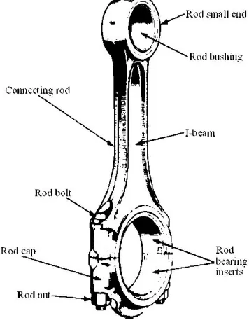
Figure 1: Connecting Rod Nomenclature
II. PRESSURE CALCULATION FOR 150CC ENGINE
Engine type air cooled 4-stroke Bore x Stroke (mm) = 57×58.6 Displacement = 149.5 CC
Maximum Power = 13.8 bhp @ 8500 rpm Maximum Torque = 13.4 Nm @ 6000 rpm
Compression Ratio = 9.35/1
= 737.22E-9 kg/mm3 Temperature = 60 o F
= 288.855 o K
Mass = Density × Volume
= 737.22E-9 x149.5E3
= 0.11kg
Molecular Weight of Petrol 114.228 g/mole From Gas Equation,
PV = Mrt R = RxMw = 8.3143/114228 = 72.76
P = (0.11×72.786×288.85) 149.5 3
P = 15.5 MPa.
III. DESIGN CALCULATION OF CONNECTING ROD
In general From standards,
Width of the section B = 4t
So, in the case of this section (assumed section) proportions shown above will be satisfactory. Length of the connecting rod (L) = 2 times the stroke
L = 117.2 mm
Total Force acting F = Fp-Fi Where Fp = force acting on piston Fi = force by inertia
Fp = ( d2/4) * gas pressure Fp = 39473.1543 N
Fi =1000wrv2 ∗ ±cos 2 Wr = weight of reciprocating parts Wr = 1.6 * 9.81 = 15.696 N
r = crank radius
r = stroke of piston / 2 r = 58.6/2 = 29.3 = Crank angle from the dead center
n1 = 117.2/29.3 = 4
g = acceleration due to gravity, 9.81 v = crank velocity m/s w = 2 /60
w = 2 8500/60 = 890.1179
v = rw = 29.3e-3*890.1179 = 26.08 on substituting
Fi = 9285.5481 Therefore
F = 39473.1543 – 9285.5481
F = 30187.6062 N
According to Rankine’s – Gordon formula,
Let,
A = C/s area of connecting rod, L = Length of connecting rod fc = Compressive yield stress, F = Buckling load
Ixx and Iyy = Radius of gyration of the section about x – x and y – y axis respectively and
Kxx and Kyy = Radius of gyration of the section about x – x and y – y axis respectively.
A. FOR ALUMINIUM 6061-9%SIC-15%FLY ASH (ALFASiC)
On substituting to rankine’s formula t = 3.5658
There fore
Width B = 4t = 14.2632 mm
Height H = 5t = 17.829 mm Area A = 11t = 139.8642 mm2
Height at the piston end H1 = 0.75H – 0.9 H H1 = 0.75*23.66 = 13.37mm
Height at the crank end H2 = 1.1H – 1.25H H2 = 1.1*23.66 = 19.6119mm
B. FOR FORGED STEEL
On substituting to rankine’s formula t = 2.5966mm
There fore
Width B = 4t = 10.3864 mm Height H = 5t = 12.983 mm Area A = 11t = 74.1656 mm2
Height at the piston end H1 = 0.75H – 0.9 H H1 = 0.75*23.66 = 9.73725mm
C. DIMENSIONS OF CONNECTING ROD Inner diameter of the small end d1 = × = 6277.16712.5×1.5d1
= 17.94mm Where,
Design bearing pressure for small end pb1=12.5 to 15.4N/mm2 Length of the piston pin l1= (1.5to 2) d1
Outer diameter of the small end = d1+2tb+2tm = 17.94 + [2×2] + [2×5]
= 31.94mm
Where,
Thickness of the bush (tb) = 2 to 5 mm Marginal thickness (tm) = 5 to 15 mm
Inner diameter of the big end d2= FgPb2 ×l2 = 6277.16710.8×1.0d1
=23.88mm Where,
Design bearing pressure for big end pb2 = 10.8 to 12.6N/mm2
Length of the crank pin l2 = (1.0 to 1.25) d2 Root diameter of the bolt = ((2Fim)(πxSt))1/2 = (2×6277.167π×56.667)1/2
= 4mm
Outer diameter of the big end = d2 + 2tb + 2db +2tm = 23.88+2×2+2×4+2×5
= 47.72mm Where,
Thickness of the bush [tb] = 2 to 5 mm Marginal thickness [tm] = 5 to 15 mm
Nominal diameter of bolt [db] = 1.2 x root diameter of the bolt = 1.2×4 = 4.8mm
Table 1: Mechanical properties of Forged Steel and ALFASiC
S.No Mechanical Property Forged Steel ALFASiC
1 Yield Strength (MPa) 415 363
2 Ultimate Strength (MPa) 625 422
3 Modulus of Elasticity (GPa) 221 70
4 Density (g/cc) 7.7 2.61161
IV. MODELLING OF CONNECTING ROD
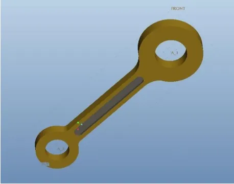
Figure 2: Pro E model of Connecting Rod
V. ANALYSING OF CONNECTING ROD 5.1. MESHING OF CONNECTING ROD
Relevance : 100
Relevance Center : Fine
Minimum Edge Length : 1.60 mm
5.2. LOADS AND CONSTRAINTS
Figure 4: Small eye end fixed Figure 5: Big eye end (Pressure – 15.5
Mpa)
5.3 ANALYSIS OF FORGED STEEL
Figure 6: Total Deformation Figure 7: Directional Deformation (x
axis)
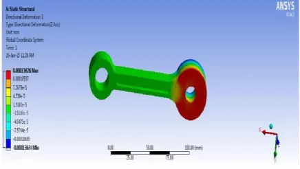
Figure 8: Directional Deformation (y axis) Figure 9: Directional Deformation (z
Figure 10: Equivalent Strain Figure 11: Equivalent Stress (Von Moises)
5.4. ANALYSIS OF ALFASiC
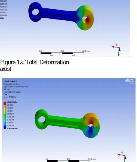
Figure 12: Total Deformation Figure 13: Directional Deformation (x
axis)
Figure 16: Equivalent Strain Figure 17: Equivalent Stress (Von Moises)
VI. RESULTS
Table 2: ANSYS Results for Connecting Rod (Forged Steel and ALFASiC)
S.No. Solution Information Forged Steel ALFASiC
1 Total Deformation (mm) 0.0025404 0.0081313
2 Directional Deformation (x axis) (mm) 0.00254 0.0081291
3 Directional Deformation (y axis) (mm) 0.0016992 0.0054717
4 Directional Deformation (z axis) (mm) 0.00013626 0.00048903
5 Equivalent Stress (Von Moises) ( MPa) Max: 38.2 Max: 38.207
Min: 1.2936e-12 Min: 2.1088e-11
6 Equivalent Strain (mm/mm) Max: 0.00017285 Max: 0.00054583
Min: 1.7335e-17 Min: 4.8918e-16
6.1 Percentage of weight reduction:
Weight of connecting Rod (Forged Steel) = 0.31 Kg Weight of connecting Rod (ALFASiC) = 0.1072 Kg
Percentage reduction of weight = 65.4194% 6.2 Percentage of Total Deformation
Total Deformation (Forged Steel) = 0.0025404 mm
Total Deformation (ALFASiC) = 0.0081313 mm
Percentage of Total Deformation = -220.0677 %
b. ALFASiC
Weight of Connecting Rod = 0.1072 kg Deformation = 0.0081313mm Stiffness = 13.1836 Kg/mm
VII. CHEMICAL COMPOSITION
a. Forged Steel
Forged Steel 0.61-0.68%C, 0.2-0.4%S, 0.5-1.2%Mn, 0.04%S, 0.04%P, 0.9-1.2%Cr b. ALFASiC
Al6061-9%SiC-15% flyash
VIII. CONCLUSION
Weight can be reduced by changing the material of the current Forged Steel connecting rod to hybrid ALFASiC composites.
Due to weight reduction in ALFASiC Connecting Rod, Engine Performance will be better.
ANSYS Equivalent Stresses Induced on both the connecting rod (Forged Steel and ALFASiC) are nearly same.
But the deformation and Stiffness of the Connecting Rod (Forged Steel) is better than the Connecting Rod (ALFASiC).
REFERENCES
[1] K. Sudershan Kumar, Dr. k. Tirupathi Reddy, Syed Altaf Hussan “Modeling and analysis of two Wheeler connecting rod”, International Journal of Modern Engineering Research, Vol -2, Issue- 5, pp-3367-3371, Sep-Oct-2012.
[2] Vivek.c.pathade, Bhumeshwar Patle, Ajay N. Ingale ”Stress Analysis of I.C. Engine Connecting Rod by FEM”, International Journal of
6.3 Stiffness of Connecting Rod a. Forged Steel
Engineering and Innovative Technology, Vol-1, Issue-3, pp-12-15, March2012.
[3] Pushpendra Kumar Sharma1, Borse Rajendra R, “fatigue analysis and optimisation of connecting rod using finiteelement analysis”, International Journal Of advance research in Science and Engineering, Vol. No.1, Issue No. I, pp-3367-3371, September 2012.
[4] Ram Bansal, “Dynamic simulation of connecting rod made of aluminium alloy using finite element analysis approach”, IOSR Journal of Mechanical and Civil Engineering, Volume 5, Issue 2, PP 01-05, Jan. - Feb. 2013.
[5] Afzal, A. and A. Fatemi, 2004. "A comparative study of fatigue behavior and life predictions of forged steel and PM connecting rods". SAE Technical Paper
[6] Chen, N., L. Han, W. Zhang and X. Hao, 2006. "Enhancing Mechanical Properties and Avoiding Cracks by Simulation of Quenching Connecting Rod". Material Letters, 61: 3021-3024.
[7] El – Sayed, M.E.M. and E.H. Lund, 1990. “Structural optimization with fatigue life constraints,” Engineering Fracture Mechanics, 37(6): 1149-1156.
[8] Jahed Motlagh, H.M. Nouban and M.H. Ashraghi, 2003. "Finite Element ANSYS". University of Tehran Publication, PP: 990. [9] Khanali, M., 2006. "Stress analysis of frontal axle of JD 955 combines". M.Sc. Thesis. Thran University, 124.
[10] Repgen, B., 1998. “Optimized Connecting Rods to Enable Higher Engine Performance and Cost Reduction,” SAE Technical Paper Series, Paper No. 980882. Books