Bending Stress Analysis of Bevel Gears
Ratnadeepsinh M. Jadeja
1, Dipeshkumar M. Chauhan
2, Jignesh D. Lakhani
3PG Student, Dept. of Mechanical Engineering, R. K. University, Rajkot, Gujarat, India 1
Assistant Professor, Dept. of Mechanical Engineering, R. K. University, Rajkot, Gujarat, India 2,3
Abstract: Gears are an integral and necessary component in our day to day lives. They are present in the satellites we communicate with, automobiles and bicycles we travel with. Gears have been around for hundreds of years and their shapes, sizes, and uses are limitless. For the vast majority of our history gears have been understood only functionally. That is to say, the way they transmit power and the size they need to be to transmit that power have been well known for many years. It was not until recently that humans began to use mathematics and engineering to more accurately and safely design these gears. Bevel gears are widely used because of their suitability towards transferring power between nonparallel shafts at almost any angle or speed. The American Gear Manufacturing Association (AGMA) has developed standards for the design, analysis, and manufacture of bevel gears.
The bending stress equation for bevel gear teeth is obtained from the Lewis bending stress equation for a beam and bending stress value derive for the spiral bevel gear, straight teeth bevel gear and zerol bevel gear. For above mentioned gear comparison between analytical value and value obtain by the ANSYS Workbench 14.0.
Keywords: Bending stress analysis, spiral bevel gear, straight teeth bevel gear, zerol bevel gear.
I. INTRODUCTION
Bevel gears are used to transmit power for non parallel shafts. Many times gear selection is become essential for each machine as per application. In some application it requires smooth function without noise. Generally one can observe that in many applications like screw type air compressor, helicopter’s rotary system, in vehicle axial etc., some of the gear set are not working quietly at higher speed and vibration generate and life cycle became smaller at higher speed. So to avoid failure, need to choose proper gear set. In this report bending stress analysis of straight teeth bevel gear, spiral bevel gear and zerol bevel gear are covered. These gears are transmitting the power at 90°. Bending stress values are obtained analytically as well as by ANSYS Workbench 14.0 for the static condition. From the comparison of analytical value and value obtain by the ANSYS for straight teeth, spiral and zerol bevel gear [2] one can conclude that which one is good for particular application.
Figure 1 - Difference between straight teeth, spiral teeth and zerol teeth
II. DESCRIPTION OF THE PROBLEM
ISSN: 2319-8753
International Journal of Innovative Research in Science, Engineering and Technology Vol. 2, Issue 7, July 2013
𝜎𝐵= 2𝑇 𝑑 𝐺𝑟 𝐹𝑚𝐽 𝐾𝑎𝐾𝑚𝐾𝑠 𝐾𝑣𝐾𝑥
Where, T = Torque = 600 Nm,
d = Diameter of gear = 219.82 mm, F = Face width = 62.35 mm, m = Module = 7.6 mm, Gr = Gear ratio = 0.58
J = Geometry factor of gear = 0.21 Ka = Application factor = 1
Km = Load distribution factor = 1.6
Ks = Size factor = 1
Kv = Dynamic factor = 1
Kx = Gear geometry factor = 1 for straight teeth bevel gear
= 1.15 for spiral bevel gear adn zerol bevel gear
For spiral bevel gear here take spiral angle is 35°, and zerol bevel gear is same as the spiral bevel gear but it is with the zero spiral angle. For straight teeth bevel gear, spiral bevel gear and zerol bevel gear all the other data is taken as same.
IV.BENDING STRESS ANALYSIS USING ANSYS
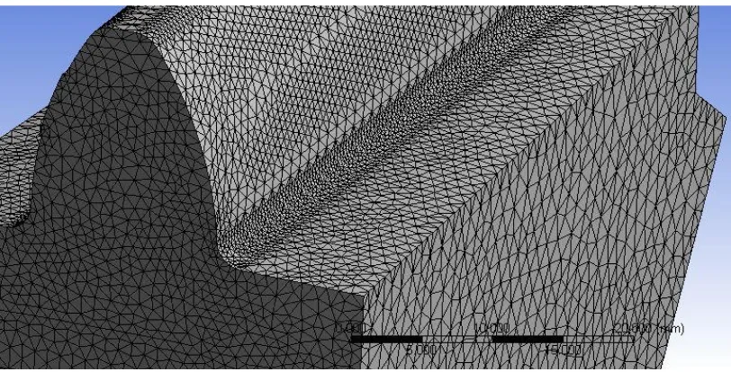
For bending stress analysis, ANSYS Workbench 14.0 is used. For the modelling of the bevel gear PTC Creo is used. Applying a mesh is necessary thing for the analysis in ANSYS. For this project tetrahedron type element and size of element is 1 mm for all other faces and 0.5 mm for those areas where the stress concentration is high.
The boundary condition and loading condition should be specified. For the analysis first apply the mesh in gear. It is not necessary to take whole gear set for the analysis, at the starting condition the load is applied on the gear teeth and the amount of load transfer from pinion to gear. At the starting condition the amount of torque is high than at the running condition the amount of torque is less. So for the analysis the only some part of the gear is taken.
Figure 2 – Meshing in gear teeth
Figure 3 – Boundary condition in Straight teeth bevel gear
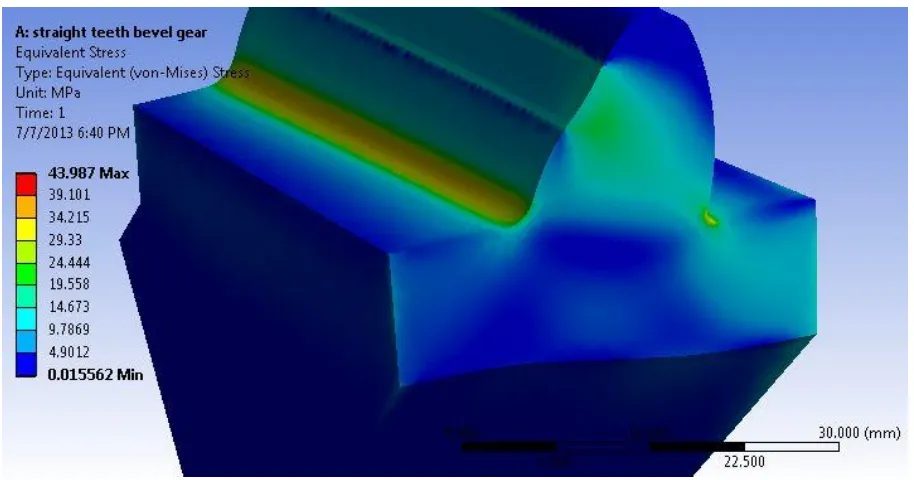
The meshing and the loading condition are the same for the spiral bevel gear as well as for the zerol bevel gear. The value of the bending stress in straight teeth bevel gear by ANSYS is shown in below figure.
Figure 4 – Bending stress distribution in straight teeth bevel gear
ISSN: 2319-8753
International Journal of Innovative Research in Science, Engineering and Technology Vol. 2, Issue 7, July 2013
Figure 5 – Total deformation in Straight teeth bevel gear due to bending stress analysis
Here as shown in figure 5 total deformation in the straight teeth bevel gear is of 0.003 mm that is affordable in bevel gear teeth.
Figure 6 – Bending stress distribution in spiral bevel gear
Figure 7 – Total deformation in Spiral bevel gear teeth due to bending stress analysis
The total deformation in the spiral bevel gear is of 0.006 mm at the tip of the teeth.
Figure 8 – Bending stress distribution in zerol bevel gear
ISSN: 2319-8753
International Journal of Innovative Research in Science, Engineering and Technology Vol. 2, Issue 7, July 2013
Figure 7 – Total deformation in zerol bevel gear teeth due to bending stress analysis
The total deformation in zerol bevel gear is 0.003 mm at the tip of the teeth of the zerol bevel gear.
V. CONCLUSION
The gearing is a very important in industrial field for power transmission. To choose high efficiency gear is very important. Here in this paper after doing the analytical calculation and analysis in ANSYS of straight teeth bevel gear, spiral bevel gear and zerol bevel gear, one conclude that the features of zerol bevel gear are good for the power transmission at higher speed and higher load. The zerol bevel gear has higher strength to resist the stress. Because of the curvature shape of the teeth load distribution is in two directional and continuously distribute the load in two directions, while in straight bevel gear load is applied in line form and at same time in full teeth.
By this paper can recommend the zerol bevel gear for transmission of power at 90° instead the spiral bevel gear and straight teeth bevel gear because of the following resion.
Zerol bevel gear can be manufactured with same machine and by using same machine tool to manufacture spiral bevel gear.
Easy to manufacture compare to straight teeth bevel gear and spiral bevel gear.
Have a high strength to resist the stress.
Work without any noise at high speed because of its curvature surface pitting effect reduces.
REFERENCES
[1] Robert L. Norton, “Machine Design an Integrated Approach” Pearson publication, Second Edition, ISBN 978-81-317-0533-9. [2] Gitin M Maitra, “Handbook of Gear Design”, Tata McGraw-Hill, Second Edition, ISBN 0-07-460237-3.
[3] Shigley, “Mechanical Engineering”, McGraw−Hill Primis, Eighth Edition, ISBN: 0−390−76487−6.