Circular Slot Rectangular
Patch MIMO
Antenna using Partially Extended Ground
Dimple Sujawat
1, Aabhas Mathur
2, Hemant Dhabhai
3Research Scholar M.Tech, Aravali Institute of Technical Studies, Udaipur, Rajasthan, India1 Head, Dept. of ECE, Aravali Institute of Technical Studies, Udaipur, Rajasthan, India2
Professor, Aravali Institute of Technical Studies, Udaipur, Rajasthan, India3
ABSTRACT: This Paper proposes Circular Slot Rectangular Patch MIMO Antenna for S-Band (2-4 GHz) and C-Band (4-8GHz ) Applications.The Antenna operating at the 2 resonant frequenices 2.37 GHz and 5.60 GHz. The proposed design uses different techniques like partial ground, Partially Extended Ground (PEG) on low cost FR4 dielectric substrate with loss tangent 0.02. The dimension of the proposed MIMO antenna is of the size 35.39 x 50.18 mm2 .The proposed MIMO covers 2.1-2.5 GHz and 5.4 -5.9 GHz frequency bands. A linearly polarized Circular slot Rectangular patch MIMO antenna resonate at 2.37 GHz and 5.60 GHz frequencies is connected to both ends of the partial ground to reduce mutual coupling between radiators. The mutual coupling is reduced using partially extended ground.
The antenna parameters such as return loss, VSWR, Envelope Correlation Coefficient (ECC), Isolation and gain are in good agreement with the requirements. The designing and simulation have been performed using CST (Computer Simulation Technology).
KEYWORDS: Partially Extended Ground (PEG), Mutual coupling, Envelope Correlation Coefficient (ECC)
I. INTRODUCTION
Day by Day people increasing demand in the mobile networks for higher capacity, higher data rate and enhance coverage area and everything is expected to a reduced cost. Wi-Fi, LTE, and many other radio, wireless and RF technologies are using the new MIMO wireless technology to provide enhance link capacity and spectral efficiency combined with improved link reliability. In high-bit-rate wireless communication for diminish multipath fading and enhance capacity, multiple-input–multiple-output (MIMO) systems are suitable[1]. Compact structure, high radiation efficiency, low envelope correlation, and high isolation between the signals ports are the characteristics of the MIMO antenna array. To achieve maximum channel capacity the array is also required having high gain and wide lobe pattern. Wireless communication systems have gone from different generations from SISO systems to MIMO systems. High data transmission rates are essential for telecommunication services [2]. Multiple Input Multiple Output (MIMO) systems have received a great attention, recently. This architecture uses more than one antenna elements in transmitter and receiver ends and is able to overcome the limit of channel capacity in a rich multipath environment. ”MIMO" specifically refers to a practical technique for sending and receiving more than one data signal simultaneously over the same radio channel by exploiting multipath propagation.
II. RELATEDWORK
In [3] authors presented various approaches of mutual coupling reduction, gain, efficiency, and diversity gain and radiation patterns improvement for MIMO antenna system. There are many techniques given in this paper which is suitable for improving all antenna parameters. To minimize the size of MIMO antennas this paper investigated the diversity and mutual coupling (correlation) reduction techniques. To control the degrading factors of mutual coupling between the radiating elements and effect of parasitic element, neutralization line, slots, coupling/decoupling structures, meta-materials, metallic/shorting pins/stubs, feeding networks, and ground branches/utilization techniques was presented in depth with their utilizations in different designs, methods were adopted. The antenna elements were slot antennas, having two quarter-wavelength slots of different lengths at the ground planes, which radiated at two distinct frequencies. They showed that Good isolation, Enhanced data rate and Envelope Correlation Coefficient (ECC) was within the threshold limits (0.004). The proposed design was very compact and exhibits comparable performance as well [4]. The MIMO antenna proposed in the paper is a combination of orthogonally arranged antennas. By using partially stepped ground (PSG) and the orthogonal arrangement of antenna elements, the effect of mutual coupling between radiating elements is reduced. It covers 2.408– 2.776 GHz and 4.96–5.64 GHz frequency bands which show good bandwidth. Between antenna elements the measured isolation in each frequency band is more than 21 dB. At 2.54 GHz and 5.26 GHz resonant frequencies, the measured gains are 3.98 dB and 4.13 dB, respectively.It is applicable for LTE bands (7/38/41), WLAN bands (2.4/5.2GHz), and WiMAX band (2.5/5.5 GHz). It gives good ECC which is very low at resonant frequencies [5].
III.DESIGNMETHODOLOGY
A. Design of Antenna
I. For an efficient antenna, a practical width is given by this formula and the calculated width is 𝑊 = 1
2 𝑓𝑟 𝜇0𝜖0
2 𝜖𝑟+ 1=
𝜐0
2𝑓𝑟 2 𝜖𝑟+ 1
Where, υ0 is the free-space velocity of light.
II. Determine the effective dielectric constant of the micro strip antenna using relation 𝑊 ℎ > 1
𝜖𝑟𝑒𝑓𝑓 =
𝜖𝑟+ 1
2 +
𝜖𝑟− 1
2 1 + 12
ℎ 𝑊
−1 2
III. Once W is found, determine the extension of the length 3L by formula
Δ𝐿
ℎ = 0.412
𝜖𝑟𝑒𝑓𝑓 + 0.3 𝑊ℎ + 0.264
𝜖𝑟𝑒𝑓𝑓 − 0.258 𝑊ℎ + 0.8
IV. The actual length (L)of the patch determined by this formula
𝐿 = 1
2𝑓𝑟 𝜖𝑟𝑒𝑓𝑓 𝜇0𝜖0
− 2Δ𝐿
V. Effective Length idetermined by given formula
B. Antenna Structure
Fig 1(a) Front Fig 1(b) Back
The Circular Slot Rectangular Patch MIMO Antenna are introduced by the 2 patch antenna with circular slot and partially ground structure. Partially extended ground [PEG] plane may be used to eliminate mutual coupling between MIMO antennas. Fig 1 Show the Front and Back Structure of MIMO Antenna.
The proposed design uses different techniques like partial ground,Circular Slot in patch and Partially Extended Ground (PEG) on low cost FR4 dielectric substrate with loss tangent 0.02. The dimension of the proposed MIMO antenna is of the size 35.39x 50.18 mm2 .The antenna is designed using CST with the dimensions as shown in Figure 1 and Table I. All the dimensions are in mm.
TABLE I: LIST OF PARAMETERS
Sr.No .
Parameter Value
1 ws 50.18
2 ls 35.39
3 wg 50.18
4 lg 7.94
5 fw 2.95
6 fl 18.48
7 wp 10.2
8 lp 12.97
9 r1 4.87
10 m 0.54
11 z1 0.99
IV.SIMULATIONRESULTS
The designed MIMO antenna system with 50 Ω ports is designed using computer simulation tool (CST Microwave Studio 2015) version 12.0. CST provides study of many parameters such as VSWR, return loss, gain, ECC, Isolation, radiation patterns, field distribution and many more. All the simulation results of designed MIMO antenna are given below:
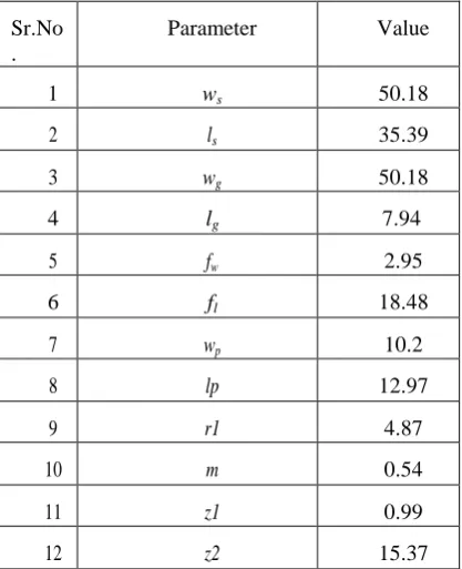
Fig 2 : Simulated Return loss of Designed MIMO antenna
Fig 2 shows the designed dual-band MIMO antenna has simulated -10 dB impedance bandwidth covers 2.1-2.5 GHz and 5.4-5.9 GHz frequency bands. We got return loss approximately 17.96 dB at 5.60 GHz and 34 dB at 2.37 GHz.
Fig 3: Simulated Isolation Factor
Fig 3 shows the designed dual-band MIMO antenna isolation at -39 dB
Fig 4: VSWR
Fig 5: ECC
The simulated value of ECC is 0.001 and is shown in Fig.5 at both the resonant frequencies. The ECC is important factor of any antenna system because it involves all the S parameters of the designed MIMO antenna and plays an important role as a grading factor of antenna. The lower correlation between antenna elements meaning is justified by the lower value of ECC.
Ant 1 Ant 2
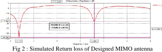
Fig.6 : Simulated 3D Gain and efficiency of Designed MIMO antenna at 2.37GHz
Ant 1 Ant 2
Fig. 7: Simulated 3D Gain and efficiency of Designed MIMO antenna at 5.60GHz
The designed patch antenna achieved moderate gain of 6 dBi which is considered good in terms of a compact antenna design. Fig 6 and Fig 7 shows the 3D omnidirectional pattern of the proposed antenna. Radiation efficiency is more than 75%.
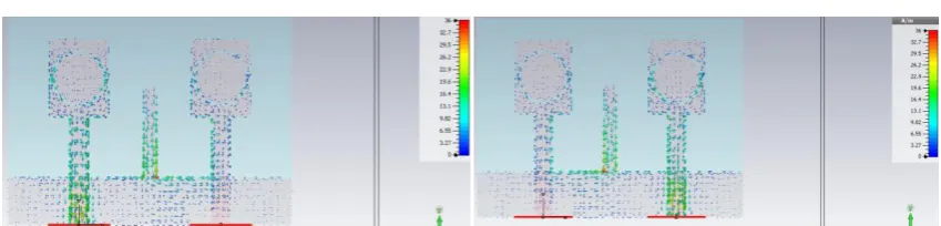
Fig. 8 Simulated Surface current distribution of designed MIMO at 2.37GHz frequency
Fig 9 Simulated surface current distribution of designed MIMO at 5.60GHz frequency
In the designed work got the size of the antenna is 35.39 x 50.18mm2 on frequency range 2.37GHz and 5.60GHz. Isolation/return loss and ECC improves using partial ground and partially extended ground. The size of the antenna is also reduced and the more bandwidth is obtained and the VSWR is lies between 1 and 2 it means the antenna is 90% radiated and in such case the reflection power is low.
V. CONCLUSIONANDFUTUREWORK
The MIMO antenna design at C and S-band has been presented. The top geometry of the suggested antenna consists of a T-shaped radiating patch with Circular Slot. The bottom part comprises of a partial ground with PEG acting as an isolator. Parametric analysis has also been performed to achieve the optimal performance of the MIMO antenna. The proposed MIMO covers 2.1-2.5GHz and 5.4-5.9GHz frequency bands. The proposed antenna has demonstrated a high impedance bandwidth and a peak gain of 6.99dBi. Moreover, the numerically calculated efficiency is above 75% in operating range. The distinguishing performance attributes of designed antenna suggest its applications in future wireless networks and cellular applications.
REFERENCES
[1] Zhai, G., Chen Z.N., and Qing X. “Enhanced isolation of a closely spaced four-element MIMO antenna system using metamaterial mushroom.”
IEEE Transactions on Antennas and Propagation. 63: 3362-3370, 2015.
[2] Ghouz, H. H. M. “Novel compact and dual-broadband microstrip MIMO antennas for wireless applications elect.” Progress in Electromagnetic omagnetics Research. 63:107-121, 2015
[3] Malviya, L., Panigrahi, R. K. and Kartikeyan, M. V.. “Four Element Planar MIMO Antenna Design for Long-Term Evolution Operation.”
Article in IETE Journal of Research. pp:1-7, 2017.
[4] Nandi, S. and Mohan, “A. A compact dual-band MIMO slot antenna for WLAN applications. IEEE Antennas and Wireless Propagation Letters.” 16:2457-2460, 2017