Performance Comparison of Diverse Routing
Protocols in Wireless Multimedia Sensor Networks
A.Sivagami1,S.Malarkkann2,S.Sandiya3,R.Ramakrishnan4
1.
Research Scholar, Sri Chandrasekharendra Saraswathi Viswa Mahavidyalaya University, Kancheepuram Dt. – 631 561, India
and
Assistant Professor in Department of Electronics & Communication Engineering, Sri Manakula Vinayagar Engineering College,Puducherry-605107 ,India.
2.
Professor & Principal, Manakula Vinayagar Institute of Technology , Puducherry – 605 107, India
3
.PG Scholar Department of Electronics & Communication Engineering, Sri Manakula Vinayagar Engineering College,Puducherry-605107 ,India.
4.
Assistant Professor in Department of Master of Computer Applications, Sri Manakula Vinayagar Engineering College,Puducherry-605107 ,India.
Abstract— The recent technological advances paved the way
to promote the development of a powerful class of sensor-based distributed intelligent systems capable of ubiquitously retrieving multimedia information, namely Wireless multimedia sensor networks(WMSNs) and are gaining more familiarity day by day as they are supporting a large number of both real time and non-real time multimedia applications. This paper proposes a procedure for enhancing the performance of video signal over WMSN by satisfying the stringent QoS requirements in a resource constrained sensor environment. As an outcome, the efficient routing procedure has suggested by comparing the QoS parameters like Residual energy, throughput, delay, signal-to-noise ratio, frame drop ratio, End-to-End delay using real time power aware routing protocol(RPAR) in combination with Hexagonal deployment with the recent routing protocols i.e. DSR and AODV. We also show that the delay tolerance level doesn’t affect the maximum lifetime of WMSN.
Keywords: WMSN, RPAR, residual energy, hexagonal
deployment.
I.INTRODUCTION
he appearance of wireless multimedia sensor networks (WMSNs) is an evolutionary action for wireless sensor networks as aural and ocular sensors are incorporated into wireless sensor nodes. It has been a spotlight to do research in a wide range of areas including digital signal processing, communication, networking and control systems. WMSNs are capable of storing, correlating and fusing multimedia data’s initiating from several camera input sources. The main purposes of WMSNs are those that yield from distributed and multi-camera image systems. Positioning multiple, low-priced ocular sensors both progresses the coverage of the application and presents for a more vigorous operation. In addition, numerous cameras offer redundancy to recover its consistency and usability. A single node failure will not cause a system failure, nor a hindrance or occlusion. Moreover, multiple ocular sources provide the suppleness to adaptively extort data depending on the obligations of the application. A distinctive application for a WMSN would be as scrutiny and
monitoring system. The WMSN provides several advantages over customary monitoring and surveillance schemes which includes:
• extending the vision. Point of view from multiple cameras can provide a lock-up view of an event either through the images confined by a camera closer the picture or by appealing a node with a more sophisticated camera such as a pan-tilt-zoom (PTZ) camera. In such a system, an event sensed by a node with a lower resolution camera can signal another node with a PTZ camera to sense and track the event.
• developing the vision. The use of multiple cameras can also improve the vision of an incident by providing a larger field of view (FOV) or by using cameras with different capacities such as integrating cameras for the visible and infrared band in the system. Such systems are very useful when the view is disguised or when there is petite or no enlightenment in the view.
These advantages provide increase in the data generated in the network which increases the energy consumption. To make sure that the typical battery-powered WMSN lifetime is not significantly affected by this, the quantity of data routed through the network can be reduced with the use of in-network progressing methods such as to eradicate redundancy from multi camera systems, discriminating transmission of the data and compressing the data. These progressing assignments can be performed at the node, cluster or scattered throughout the network. The use of error detection and correction also reduces the likelihood of a valuable retransmission. Aspects such as deployment compactness, outlay, range and geographic location determine the components for the implementation of a specific WMSN.
a) Network architecture
neighbouring sensor nodes. Conventionally, the study on protocols for sensor networks has decisive on scalability. Flat topologies are not suitable for handling the quantity of traffic engendered by multimedia applications including audio and video etc. Similarly, the progressing power essential for data processing and communications, and the power essential to drive it, may not be available on each node.
(i)Reference architecture:
Fig.1. General Architecture of WMSN [30] . In Fig.1,three sensor networks with dissimilar characteristics which are deployed in different physical locations. The first block represents a single-tier network of homogeneous multimedia sensors and the split of the positioned sensors has elevated processing capacities, and it is known as processing hubs. The blending of the processing hubs represents a dispersed processing architecture. The video and audio content grouped is relayed to a gateway which is in wireless mode passes through a multi-hop course. The gateway is unified to a cargo space hub, which is responsible of storing multimedia content locally for ensuing retrieval. Evidently, additional complex architectures for spread storage can be realized when permitted by the location and the application requires, which may give rise to energy reduction because by storing it in the vicinity, the multimedia content does not necessitate to be wirelessly relayed to inaccessible locations. The wireless gateway is also linked to a vital sink, which realizes the software front-end for system reservation and tasking. The second block represents a single-tiered clustered design of heterogeneous sensors (only one cluster is illustrated). Multimedia and scalar sensors impart data to a central cluster head, which is responsible of performing intensive multimedia processing on the information (processing hub). The cluster head relays the grouped content to the gateway and to the storage hub. The final block on the right describes a multi-tiered network, with heterogeneous sensors. Each tier is responsible of a subset of the functionalities. Resource-constrained, low-power scalar sensors are in charge of performing simpler tasks, such as detecting scalar physical measurements, while resource-rich, elevated-power devices are responsible for more complex tasks. Data processing and storage can be performed in a distributed fashion at each different tier.
(ii) Single-tier vs. multi-tier sensor deployment:
One possible approach for designing a multimedia sensor application is to deploy homogeneous sensors and
program each sensor to perform all possible application tasks. Such an approach yields a flat, single-tier network of homogeneous sensor nodes. An alternative, multi-tier approach is to use heterogeneous elements . In this advance, resource-constrained, low-power elements are responsible of performing simpler tasks, for instance detecting scalar physical measurements, while resource rich, elevated-power devices take on more complex tasks. For example, a surveillance application can rely on low-fidelity cameras or scalar aural sensors to perform motion or invasion detection, while high-fidelity cameras can be woken up on-demand for object detection and tracking. In[2] , a multi-tier architecture is sponsored for video sensor networks for surveillance applications. The architecture is based on multiple tiers of cameras with dissimilar functionalities, with the lower tier constituted of low-resolution imaging sensors, and the higher tier composed of high-end pan-tilt-zoom cameras. It is argued, and shown by means of experiments, that such an architecture offers considerable advantages with respect to a single-tier architecture in terms of scalability, lower cost, better coverage, higher functionality, and better reliability. (iii) Coverage
In conventional WSNs, sensor nodes collect data from the surroundings within a pre-defined sensing range, i.e., an approximately circular area defined by the type of sensor being used. WMSNs generally have larger sensing radii and are also sensitive to the course of data acquisition. Especially, cameras can capture images of objects or parts of regions that are not essentially close to the camera itself. Nevertheless, the image can perceptibly be captured only when there is an unobstructed line-of-sight between the event and the sensor. Furthermore, each multimedia sensor/camera perceives the environment or the observed object from a different and unique viewpoint, given the different orientations and positions of the cameras relative to the observed event or region. In [4], a preliminary investigation of the coverage problem for video sensor networks is conducted. The concept of sensing range is replaced with the camera’s field of view, i.e., the maximum volume visible from the camera. It is also shown how an algorithm designed for traditional sensor networks does not perform well with video sensors in terms of coverage preservation of the monitored area.
b)Node Deployment
Node deployment approaches are classified into two major categories i.e. random deployment and deterministic deployment of node.
(i)Random Node Deployment:
coverage i.e. to cover an area it should use minimum sensor nodes. But in general, it does not work properly because the prospect of throwing nodes on their accurate locations is very less.
(ii)Deterministic Node Deployment:
The positions of nodes are predefined in Deterministic node deployment i.e. the sensor nodes are deployed in the calculated positions only. The deterministic deployment are employed in operations where the deployment area is actually reachable. When compared to random deployment, this method uses lesser number of nodes to wrap an area. Therefore it is more preferable when compared to random deployment.
There are three major categories in deterministic node deployment method for deployment of sensor nodes i.e. triangle grid, square grid and a hexagon grid method are analyzed by considering number of required nodes, coverage, delay and energy consumption.
a)Hexagonal grid:
A grid-based deployment is considered as a excellent deployment in WMSNs, mainly for the coverage concert. There are several grid based designs like as unit square, equilateral triangle, regular hexagon etc. We have chosen the standard hexagon grid deployment pattern for the estimation purpose.
Fig.2. A standard hexagonal grid based node deployment.
A standard hexagon based node deployment pattern is shown above in fig (2). Each of the sensor nodes are deployed on the intersection points of the grid in a considered circular field with radius, say R. The pattern within a circular field with radius R is assumed to be symmetric i.e. all the unit cells within the circular field have equal edge length D and thus equal area within each unit hexagon cell.
c) Video Signal Compression
(i)MPEG-4 part 10 AVC (H.264) video encoding:
H.264 is also a video compression format which is one of the most widely used formats at present for video recording, solidity, and delivery of video content[16]. H.264 is basically used for lossy compression, even though the amount of loss may sometimes be indiscernible. H.264 is also capable of creating lossless encodings — e.g., to have restricted lossless-coded provinces within lossy-coded pictures or to support unusual cases for which the complete
encoding is lossless[43]. Thus H.264 AVC coding in MPEG-4 is efficient than other compression technique.
(ii)Advantages:
The following are some of the prime advantages of H.264:
1. Bit rate savings: Compared to MPEG-2 or MPEG-4, undemanding silhouette, H.264 authorizes a bit rate up to 50% for an analogous degree of encoder optimization.
2. sky-scraping quality video: H.264 proposes unswervingly good video quality at high and low bit rates.
3. Error buoyancy: H.264 affords the tools indispensable to covenant with packet loss in packet networks and bit errors in wireless networks[45].
4. Network affability: In the course of the Network Adaptation Layer, that is the identical as for MPEG-2, H.264 bit streams can be easily elated over diverse networks.
The above advantages make H.264 an ideal standard for offering TV services over bandwidth restricted networks, such as DSL networks, or for HDTV.
II.RELATED WORKS IN QOS ANALYSIS
A.QoS Support
QoS can be achieved by considering admission control, policy managers, traffic classes, and queuing mechanisms.Wireless Local Area Networks (WLANs) and Broadband Wireless Access Networks (BWANs) are infrastructure based wireless network which are the extension of wired networks, so that the connections can be extended to mobile users. QoS challenges are mainly due to the scarcity of bandwidth and the complexity of user mobility through the last wireless hop.
B.QoS Requirements
A Wireless sensor network is collection of a large number of sensor nodes spreaded over a environment. Each has the capability of collecting data about an ambient condition , and deliver it to a specified sink node. Since there exist many imagined applications in WSNs and their QoS requirements may be very different, it is impossible to analyze them individually. Also, it is unlikely that there will be a “one-size-fits-all” QoS support solution for each application.
For this purpose we describe QoS in WSNs as: (i)Application-specific QoS:
Application specific QoS considers parameters such as coverage [19], exposure [20], measurement errors, and optimum number of active sensors [12].
(ii)Network QoS:
• End-to-end[2]: The performance may be end-to-end or non-end-to-end depending upon the applications.
• Interactivity: The performance may be interactive or non- interactive depending upon the applications.
• Characteristics: The performance may or may not be with delay tolerant depending upon the applications. • Criticality: The performance may or may not be mission- critical depending upon the applications.
C.QoS Provisioning- Issues & Challenges (i) Issues:
QoS-enabled traditional networks attempt to ensure: • That applications/users satisfy their QoS requirements, with efficient resource usage, i.e. efficient bandwidth utilization.
• That the most important traffic still has its QoS requirements to be satisfied during network overload. In WSNs, efficient resource usage considers both efficient bandwidth utilization, and negligible usage of energy. Thus QoS control mechanisms is also included to support QoS requirements which eliminates unnecessary energy consumption in data delivery. Moreover, during network overload, the most important traffic should still have its QoS[35] requirements satisfied in the presence of different types of network dynamics, which may arise from node failure, wireless link failure, node mobility, and node state transition.
(ii) Challenges:
Since WSNs have to interact with the surroundings and so their characteristics can be expected to be very different from other conventional data networks,which are considered as follows.
(i) Severe resource constraints: The resource constraints involves energy, bandwidth, memory, buffer size, processing capability, and limited transmission power. Among these resources, energy is a primary concern which cannot be recharged or replaced . As a result, these constraints inflict an essential requirement on any QoS support mechanisms in WSNs.
(ii) Unbalanced traffic: Traffic priority mainly flows from a large number of sensor nodes to a small subset of sink nodes in most of the applications in WSNs. QoS mechanisms are always designed for an unbalanced QoS-constrained traffic only.
(iii) Data redundancy: While decreasing redundancy in the data,Data fusion or data aggregation is a solution to maintain robustness. But this mechanism also introduces latency and complicates QoS design in WSNs.
(iv) Network dynamics: Network dynamics are happened due to node failures, wireless link failures, node mobility, and node state transitions which are araised from usage of power management or energy efficient schemes. Such a highly dynamic network greatly increases the complexity of QoS support.
(v) Energy balance: When energy load are evenly distributed among all sensor nodes, network lifetime increases where the energy at a single sensor node or a small set of sensor nodes will not be drained out very soon.
(vi) Scalability: Scalability should be achieved even when a large number of sensor nodes are deployed with QoS support. ie., QoS support should not degrade quickly when the number of nodes or their density increases.
(vii) Multiple sinks: There may exist multiple sink nodes, which impose different requirements on the network. WSNs should be able to support different QoS levels associated with different sinks.
(viii) Multiple traffic types: Inclusion of heterogeneous sets of sensors raises challenges for QoS support. (ix) Packet criticality: The content of data or high-level description reflects the criticality of the real physical phenomena and is thereby of different criticality or priority with respect to the quality of the applications [21]. QoS mechanisms may be required to differentiate packet importance and set up a priority structure.
As a result, these challenges are taken into account to achieve better QoS requirements when an application is specified.
III.ROUTING PROTOCOLS
In WMSNs there are different criteria for classifying routing protocols for wireless Ad Hoc networks. Routing protocols are classified into two major types based on how and when routes are discovered: proactive or table driven, and reactive or on-demand. In the proactive routing protocols, each node keeps its routing table updated with the route to each node in the network whether it needs it or not by sending control messages periodically between the hosts which update their routing tables. In proactive routing, each node has one or more routing tables that contain the latest information on the routes to any node in the network. The proactive routing protocols are based on either link-state or distance vector principles to maintain routes to every node in the network [14]. An example of proactive routing protocol is the Optimized Link State Routing Protocol (OLSR).
On the other hand, reactive routing is also known as an on-demand routing protocol since the nodes search routes to needed nodes only. Reactive protocols do not maintain routing information or routing activity at the network nodes if there is no communication. If a node needs to send a packet to another node, then the reactive protocol starts the route discovery operation in an on-demand manner, and when the route is established, the source node starts to send its packets via the established route to the destination. The route discovery usually occurs by flooding route request packets throughout the network. Examples of reactive routing protocols are the Dynamic Source Routing (DSR) and Ad hoc On-demand Distance Vector routing (AODV). The next sub-section describes the basic features of these protocols.
(i)Ad Hoc On Demand Distance Vector Routing Protocol (AODV)
available routers. The protocol supports unicast, broadcast, and multicast [15]. Each node maintains a sequence number which saves a time stamp, and a routing table which contains routes to destinations. The routing table consists of a number of entries (one entry per destination is allowed). Each table entry contains the address of the next hop (next node to the destination), a hop count (number of hops to the destination) and a destination sequence number. Since this is an on-demand distance vector scheme routers maintain distances of only those destinations that they need to contact or relay information to[36]. Each active route is associated with a lifetime stored in the table; after this time has passed, route timeout is triggered, and the route is marked as invalid and later on, removed. AODV can deal with any kind of mobility rate and a variety of data traffic. The two main mechanisms used by the AODV protocol to establish and maintain the connection between any pair of nodes are as follows:
1. Route Discovery mechanism[15] 2. Route Maintenance mechanism. (a)Route Discovery Mechanism in AODV
If a sender (source node) needs a route to a destination, it broadcasts a ROUTE REQUEST (RREQ) message. Every node also maintains a broadcast id which, when taken together with the originator’s IP address, uniquely identifies a RREQ. Every time a sender issues a RREQ, it increments its broadcast id and sequence number by one. The sender buffers this RREQ for PATH DISCOVERY TIME (PDT) so that it does not reprocess it when its neighbours send it back. The sender then waits for NET TRAVERSAL TIME (NETT) for a ROUTE REPLY (RREP). If a RREP is not received within this time, the sender will rebroadcast another RREQ up to RREQ TRIES times. With each additional attempt, the waiting time (NETT) is doubled. When a node receives a RREQ message it has not seen before, it sets up a reverse route back to the node where the RREQ came from. This reverse route has a lifetime value of ACTIVE ROUTE TIMEOUT (ART). The reverse route entry is stored along with the information about the requested destination address. If the node that receives this message does not have a route to the destination, it rebroadcasts the RREQ[37]. Each node keeps track of the number of hops the message has made, as well as which node has sent it the broadcast RREQ.
Fig.3, AODV mechanism.
As represented in fig.3, if a node has a route to the destination, it then replies by unicasting a RREP back to the node it received the request from. The reply is sent back to the sender via the reverse route set by the RREQ. The RREP broadcasts back to the source; nodes set up forward indicators to the destination. As soon as the source node receives the RREP, the route has been established and the source starts to send data packets to the destination. AODV includes an optimization mechanism to control the RREQ flood in the route discovery process. It uses an expanding ring search initially to discover routes to an unknown destination. In the expanding ring search, increasingly larger neighborhoods are searched to find the destination. The search is controlled by the TTL field in the IP header of the RREQ packets. If the route to a previously known destination is needed, the prior hop-wise distance is used to optimize the search [16, 17].
(b) Route Maintenance Mechanism in AODV
The role of route maintenance is to provide feedback to the sender in case a link breakage occurs, to allow the route to be modified or re-discovered. A route can stop working simply because one of the mobile nodes has moved. If a source node moves, then it must rediscover a new route. If an intermediate node moves, it must inform all its neighbours that may need this hop. This new message is forwarded to all the other hops and the old route is deleted. The source node must then rediscover a new route or else the module upstream of that smash may prefer to repair the link in the vicinity if the destination was no further than MAX_REPAIR_TTL hops left. To fix the link break, the node increases the sequence number for the destination and then broadcasts a RREQ for that particular destination. One proposed way for a node to keep track of its neighbors is by using HELLO messages. These are periodically sent to detect link failures. Upon receiving notification of a broken link, the source node can restart the rediscovery process[18]. If there is a link breakage, a ROUTE ERROR (RERR) message can be broadcast on the net. Any host that receives the RERR invalidates the route and rebroadcasts the error messages with the unreachable destination information to all nodes in the network.
(a)Advantage of AODV
1.AODV can respond very quickly to the topological changes that affect the active routes, because of its adaptability to highly dynamic networks.AODV routing protocol.
2. AODV can support both unicast and multicast packet transmissions, even for nodes in constant movement. 3. AODV has lower setup delay for connections and detection of the latest route to the destination
4. AODV does not put any additional overheads on data packets as it does not make use of source routing.
5. AODV protocol is a flat routing protocol. It does not need any central administrative system to handle the routing process.
6. AODV is loop-free, self starting, and scales to a large number of mobile nodes.
with a smaller hop count, it may update its routing data for that destination and begin using the better route.
(ii)Dynamic Source Routing (DSR) Protocol
Dynamic Source Routing (DSR) is a reactive, on-demand routing protocol for wireless Ad Hoc networks and is based on a method known as source routing [19], that is, the sender knows the complete hop-by-hop route to the destination. Nodes in a DSR broadcast route request on on-demand bases if the node does not have the required route in its routing table. Nodes in DSR ‘learn’ and cache multiple routes to each destination (either as a response to a request, forwarding, or overhearing) to be used in case of route loss. In addition, this also helps in reducing routing overheads. The on-demand feature of DSR reduces the bandwidth use, especially in cases where the mobility is low [19]. Several additional optimizations have been proposed such as:
1. Salvaging: An intermediate node can use an alternate route from its own cache, when a data packet meets a failed link on its source route.
2. Gratuitous route repair: A source node receiving a RERR packet piggybacks the RERR on the following RREQ. This helps clean up the caches of other nodes in the network that may have the failed link in one of the cached source routes. 3. Promiscuous listening: When a node overhears a packet not addressed to it, it checks if the packet could be routed via itself to gain a shorter route.
The DSR uses two main mechanisms: Route Discovery and Route Maintenance, which work together to enable nodes to discover routes to destinations, and to maintain the routes to prevent any loss [19].
(iii)RPAR Routing Protocol[25]
Real time power aware routing protocol(RPAR) is the press forwarded version of RAP. It is the only protocol that is devised to sustain the real time routing for WSNs. Appliance precise communication delays are fingered in this protocol by vibrantly adapting transmission power and routing pronouncements based on the packet targets. RPAR exercises promoting policy with neighbourhood manager and power responsive that efficiently ascertains eligible vicinity node to forward the packet in WSNs.
The main aspect of this scrupulous protocol is its adaptability, i.e. for rigid time limits, it trades energy and capacity to congregate the craving time constraints, and for unfastened deadlines, it reduces the transmission power to enhance the throughput. The protocol architecture consists of four sections as follows:
(i) Dynamic velocity: Dynamic velocity module, which sketchs a packet deadline to a entailed packet velocity. When a node promotes a packet, it uses the velocity module to subtract the necessitate velocity based on the lingering distance between the present node and the destination node and time to live (TTL). It also prioritizes the packet based on their destination.
(ii)Delay estimator: Delay estimator module, which scrutinizes the one-hop delay of diverse forwarding choices.
(iii)Forwarding: Forwarding module composes forwarding decisions on packet-by-packet. It forwards the packet to the
majority energy efficient forwarding choice that convenes the required velocity of the packet.
(iv)Neighbourhood manager: Neighbourhood manager proficiently holds the neighbourhood table and affords the best neighbor for the transmission of packets[31]. If there is no information in neighborhood table about entitled forwarding node then the neighborhood manager is heaved to discover the forwarding choices with two methods power adaptation and neighbor discovery.
a)Power adaption: In the power adaptation scheme, the required velocity for the subsisting neighbors in the neighborhood table is done by improving the transmission power. In this process, new neighbors are revealed that assemble the entailed velocity by sending the Route to Request (RTR) packets to the neighbor nodes. The projected power adaption and neighborhood mechanisms are stipulated and so this protocol is said to be a reactive protocol[32]. This reactive loom is helpful in discovering neighbors rapidly with low control overhead. This protocol addresses vital practical issues like broken links, bandwidth constraints and scalability. Concert results show that this protocol achieves well in terms of energy consumption and deadline neglect ratio.
IV.RESULTS &DISCUSSION
(i)Simulation Environment:
For our simulation we used NS2 network simulator to simulate packet transmission over the network. Moreover, we generated MPEG4 [13] video traffic by using Evalvid [14, 15,16] frame work. In this frame work we use ffmpeg [17] encoder. Metrics of interest are throughput, end-to-end delay, percentage of frame drop ratio, etc.
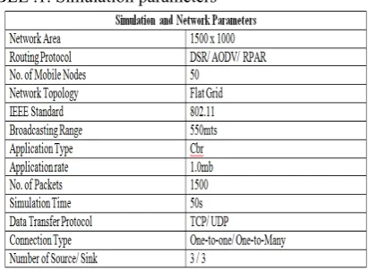
(ii)Simulation parameter:
TABLE .1. Simulation parameters
Simulation parameters are listed in the table. (iii)NAM file output:
Fig.4 Snapshot of the simulation in NAM for 100 mobile nodes.
Fig.5 Snapshot of the simulation in NAM with AODV routing protocol
Fig.6 Snapshot of the simulation in NAM with DSR routing protocol.
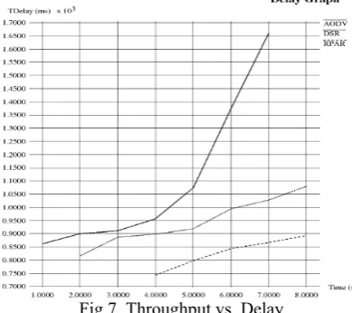
(iv).Graph analysis: (a). End-to-End delay:
As shown in Figure 7, the number of nodes increases
average End to End Delay also increases. Graph shows that RPAR has minimum End to End Delay than AODV & DSR. According to simulation result; best performance is shown by RPAR having lowest End to End Delay.
Fig 7. Throughput vs. Delay
(b). Frame drop ratio:
Frame drop ratio is the amount of information dropped from the network[38]. According to simulation result, best performance is given by RPAR routing protocol with minimum Frame drop ratio.
Fig.8. Time vs. Frame drop.
(c).Throughput:
Throughput[39] is the total number of packet that is passing through the channel in a particular period of time that have been successfully delivered from source node to destination node and it can be improved with increasing node density. RPAR gives higher throughput ratio when compared to AODV and DSR routing protocol.
Fig.9. Time vs. Frame rate
(d) Residual Energy
As shown in Figure10, using RPAR, the throughput increases energy consumed by the nodes in the environment decreases.
(e) Signal-to-noise Ratio:
As shown in Figure 11, RPAR shows better SNR ratio when compared to AODV and DSR routing protocol.
Fig.11. Time vs. SNR
V.CONCLUSION
In this paper, we proposed a framework for improving network lifetime by exploiting sink mobility and delay tolerance. In this, the coverage area is explicitly modelled and a trade off between coverage area and network lifetime is established. To validate the framework’s ability, we compare the QoS parameters like Residual energy, throughput, delay, signal-to-noise ratio, frame drop ratio, End-to-End delay for RPAR with fixed deployment using video traffic with the recent routing protocols like DSR & AODV and the results showed that the RPAR outperforms other protocols. This work can be further extended to heterogeneous traffic with mobile nodes.
REFERENCES
[1] Sung-Keun Lee,.et al,’’An Energy Efficient QoS-aware Routing Algorithm for Wireless Multimedia Sensor Networks’’,International Journal of Multimedia and Ubiquitous Engineering, vol.9,no.2(2014).
[2] Junho Park,et al,’’Disjointed Multipath Routing for Real-Time Data in Wireless Multimedia Sensor Networks’’,International Journal of Distributed Sensor Networks,vol.1(2014).
[3] Sung-Keun Lee,.et al,’’An Energy Efficient QoS-aware Routing Algorithm for Wireless Multimedia Sensor Networks’’,International Journal of Multimedia and Ubiquitous Engineering, vol.9,no.2(2014).
[4] S. Ponlatha and R. S. Sabeenian“Comparison of Video Compression Standards” International Journal of Computer and Electrical Engineering, Vol. 5, No. 6, Dec 2013.
[5] Mohammed Abazeed et al,’’Routing protocol for wireless Multimedia sensor Networks’’,Journal of Sensors,vol.2013(2013). [6] F. Ullah, M. Amin and H. Ghaffar, “Simulating AODV and DSDV
For A dynamic Wireless Sensor Networks,” International Journal of Computer Science and Network Security, Vol.10, No.7, pp. 219-223, July, 2010. Last accesed in Jan 2012.
[7] N. Vetrivelan and A. V. Reddy, “Performance Analysis of Three Routing Protocols for Varying MANET Size,” Proceedings of the International MultiConference of Engineers and Computer Scientists, Vol. 2, Mar 2008. Last accesed in Mar 2012.
[8] S. Gowrishankar, T.G. Basavaraju, M. Singh and S. Sarkar, “Scenario based Performance Analysis of AODV and OLSR in Mobile Ad hoc Networks,” Proceedings of the 24th South East Asia Regional Computer Conference, Nov. 2007. Last accesed in Mar 2012.
[9] “The Network Simulator – ns-2”, available at:
www.isi.edu/nsnam/ns. Last accessed in Mar 2012.
[10] Neha Rathi et al,’’A Review on routing protocols for application in wireless sensor networks’’,International Journal of Distributed and Parallel Systems(IJDPS) vol.3,No.5,Sep 2012.
[11] Kai lin et al,’’Energy Efficiency QoS Assurance Routing in Wireless Multimedia Sensor Networks’’,system journal,vol.5,Dec 2011. [12] Prabhat K. Andleigh and Kiran Thakrar, ― Multimedia System
Design,2011.
[13] S. Sathish, K. Thangavel and S. Boopathi ―Comparative Analysis of DSR, FSR and ZRP Routing Protocols in MANETǁInternational Conference onInformation and Network Technology IPCSIT vol.4, Singapore, pages 238-243, 2011.
[14] M. N. Jambli, K. Zen, H. Lenando and A. Tully, “Performance Evaluation of AODV Routing Protocol for Mobile Wireless Sensor Network,” 7th International Conference on IT in Asia (CITA), IEEE 2011.
[15] M. Pandey and S. Verma, “Performance Evaluation of AODV for different Mobility Conditions in WSN,” International Conference on Multimedia, Signal Processing and Communication Technologies, pp. 240-243, IEEE 2011.
[16] Eunil Park and Kwangsu Cho, (2010) “Energy Efficient and Reliable Geographic Routing in Wireless Sensor Networks”, World Academy of Science, Engineering and Technology 37.
[17] Nandini .S.Patil and P. R. Patil, “Data Aggregation in Wireless Sensor Network”, IEEE International Conference on Computational Intelligence and Computing Research, 2010.
[18] Harminder S. Bindra, Sunil K. Maakar and A. L.Sangal, ―Performance Evaluation of Two Reactive Routing Protocols of MANET using Group Mobilit Modelǁ of IJCSI International Journal Computer Scienc Issues, Vol. 7, Issue 3, No 10, pages 38-43, May 2010.
[19] S. Muthukarpagam, V. Niveditta andNedunchelivan, (2010) “Design issues, Topology issues, Quality of Service Support for Wireless Sensor Networks: Survey and Research Challenges”, IJCA Journal.
[20] J. Zheng and A. Jamalipour, “Wireless Sensor Networks A Networking Perspective,” by Institute of Electrical and Electronics Engineers, first edition, 2009.
[21] P. Loh, H. Jing and Y. Pan, “Performance Evaluation of Efficient and Reliable Routing Protocols for Fixed-Power Sensor Networks,” IEEE TRANSACTIONS ON WIRELESS COMMUNICATIONS, Vol. 8, No. 5, 2009.
[22] Sidra Aslam, Farrah Farooq and ShahzadSarwar, (2009) “Power Consumption in Wireless Sensor Networks”, Proceedings of the 7th International Conference on Frontiers of Information Technology. [23] WintYe Poe and Jens B. Schmitt, “Node Deployment in Large
Wireless Sensor Networks: Coverage,Energy consumption, and
Worst–Case Delay”, Proceeding AINTEC’09 Asian internet
engineeringcollege, pp. 77-84.
[24] Luis Javier GarcíaVillalba and Ana Lucila Sandoval Orozco, “Routing Protocols in Wireless Sensor Networks”, Oct 2009. [25] N. Vassileva and F. Barcelo-Arroyo, “A Survey of Routing
Protocols for Maximizing the Lifetime of Ad Hoc Wireless Networks”, International Journal of Software Engineering and Its Applications, vol. 2, no. 3, (2008), pp. 77-90.
[26] John A. Stankovic, “Wireless Sensor Networks”, computer, vol. 41, pp. 92-95, Oct. 2008.
[27] Janio M. Monteiro, Carlos T. Calafate, and Mario S. Nunes, “Evaluation of the H.264 Scalable Video Coding in Error Prone IP Networks,” IEEE Transactions on Broadcasting, Vol. 54, No. 3, Sep 2008, pp. 652–659
[28] X. Huang, et al., “Multiconstrained QoS multipath routing in wireless sensor networks”, Wireless Networks, vol. 14, (2008), pp. 465-478.
[29] H. Oh and K. Chae, “An Energy-Efficient Sensor Routing with Low Latency, Scalability for Smart Home Networks”, IJSH, vol. 1, no. 2,
(2007), pp. 71-81.
[30] I. F. Akyildiz, et al., “A survey on wireless multimedia sensor networks”, Computer Networks, vol. 51, no. 4, (2007), pp. 921-960.
[31] M. Chen, et al., “Directional geographical routing for real-time video communications in wireless sensor networks”, Computer Communications, vol. 30, (2007), pp. 3368-3383.
[32] C. Yin and A. Orooji “Routing Protocols for Sensor Networks,” In Proceedings of ICWN' 2006. pp. 15-21.
[33] E. Felemban, et al., “MMSPEED: Multipath Multi-SPEED Protocol for QoS Guarantee of Reliability and Timeliness in WSNs”, IEEE TMC, vol. 5, (2006), pp. 738-754.
[34] K. Akkaya and M. Younes, “A survey on routing protocols for wireless sensor networks”, Ad hoc Networks, vol. 3, no. 3, (2005),
[35] IEEE 802.11 WG. IEEE 802.11e, Medium Access Control (MAC) Quality of Service (QoS) Enhancements. Draft Supplement to IEEE 802.11 Standard, 2005.
[36] V. Naumov, T. Gross, “Scalability of routing methods in ad hoc networks,” Elsevier Performance Evaluation Journal, Vol. 62, 2005. [37] Rajashree.V.Biradar, V. C. Patil,Dr. S. R. Sawan andDr. R. R.
Mudholkar, “Classification and Comparison of Routing Protocols in Wireless Sensor Networks”, UbiCCJournal,Vol. 4.
[38] Jamal, N.Al-Karaki and Ahmed E. Kamal, “Routing techniques in wireless sensor networks: a survey”, Wireless Communications, IEEE, vol. 11, pp. 6-28, Dec. 2004.
[39] R. de Renesse, M. Ghassemian, V. Friderikos and A. Hamid Aghvami, ―QoS Enabled Routing in Mobile Ad hoc Networksǁ, Fifth IEE International Conference on 3G Mobile Communica-tion Technologies, Page(s):678 – 682, 2004.
[40] D.B. Johnson, D.A. Maltz, and Y-C Hu, ―The Dynamic Source Rout ing for Mobile Ad-hoc Networks,ǁIETF Internet draft, 19 July 2004. [41] C. Perkins, E. Belding-Royer, S. Das. Ad hoc On-Demand Dis-tance Vector (AODV) Rout ing, RFC 3561, Jul 2003. [41] Jason Lester Hill and David E. Culler, (2003) “System Architecture
for Wireless Sensor Networks”, Proceedings of the Doctoral Dissertation System architecture for wireless sensor networks. [42] D. Marpe, H. Schwarz, and T. Wiegand, “Context-Based Adaptive
Binary Arithmetic Coding in the H.264/AVC Video Compression Standard,” IEEE Transactions on Circuits and Systems for Video Technology, vol. 13, no. 7, pp. 620-636, 2003.
[43] I. E. G. Richardson, H.264 and MPEG-4 Video Compression, UK Wiley, 2003.
[44] D. Marpe, H. Schwarz, and T. Wiegand, “Context-Based Adaptive Binary Arithmetic Coding in the H.264/AVC Video Compression Standard,” IEEE Transactions on Circuits andSystems for Video Technology, vol. 13, no. 7, pp. 620-636, 2003.