ARTICULATIONS IN FLOATING ARRAYS
By
ABBAS NOBAKHTI
A thesis Submitted for the Degree of Doctor of Philosophy In the Faculty of Engineering, University of London
Department of Mechanical Engineering University College London
All rights reserved
INFORMATION TO ALL USERS
The quality of this reproduction is dependent upon the quality of the copy submitted. In the unlikely event that the author did not send a complete manuscript and there are missing pages, these will be noted. Also, if material had to be removed,
a note will indicate the deletion.
uest.
ProQuest U642068
Published by ProQuest LLC(2015). Copyright of the Dissertation is held by the Author. All rights reserved.
This work is protected against unauthorized copying under Title 17, United States Code. Microform Edition © ProQuest LLC.
ProQuest LLC
789 East Eisenhower Parkway P.O. Box 1346
This thesis describes an investigation principally to explore the displacements due to static loading of floating structures, which consist of several similar modules connected together. The study includes theoretical development and experimental work of both in-line and mat arrays of modules.
To establish module displacements it is necessary to find the stiffness matrix. For the in-line array two methods have been employed. First, by the use of constraint equations which are inserted in the global stiffness matrix. In this case each module is considered as a rigid body and the displacements result from hydrostatic stiffness represented by elastic foundation. The second method is by the use of the finite element method, and potential energy, in which the structural stiffness matrix is due to the elasticity of the structure, and the hydrostatic stiffness matrix represented as an elastic foundation. The effects of connections play an important role and these are considered in the study. For the mat array constraint equations are employed. Different connections, such as hinged, elastic, rigid, and hinged- rigid are evaluated. The main emphasis is concentrated on hinged-rigid connections. For these the system behaves as a hinged connection between consecutive modules up to threshold value and after that the system will act rigidly.
The experimental work for in-line arrays is reported for hinged-rigid connections with different arrangements, different locking angles between consecutive modules, and also for several loading conditions. The hinged and hinged-rigid connections were used in experimental work for the mat array with several loading conditions.
I would first like to thank the Ministry of Culture and Higher Education of the Islamic Republic of Iran for providing an opportunity and finance for my Ph.D. research work.
I would like to express my sincere gratitude to my supervisors, Dr G J Lyons and Dr D T Brown for their valuable guidance, advice, help and especially their support throughout this work.
I wish to thank Professor D R Broome and Dr K R Drake for their valuable advice and suggestions.
My thanks also go to Mr O Pearson and Mr M Dixon at the Santa Fe Laboratory for Offshore Engineering for their friendly help.
ABSTRACT...2
ACKNOWLEDGEMENT... 4
CONTENTS...5
GLOSSARY OF KEY SYMBOLS AND ABBREVIATIONS... 10
CHAPTER 1 INTRODUCTION... 12
1.0 Principal aims... 12
1.1 Overview... 12
1.1.1 Connection types... 13
1.2 Applications of multipli-connected floating structures...14
1.2.1 Wave energy devices... 14
1.2.2 Wave breakers...14
1.2.3 Floating marine terminals...15
1.2.4 Other uses... 15
1.3 Objectives of present work... 16
1.3.1 Connection type...16
1.3.2 Structural arrangement... 16
1.3.3 Hinged-rigid connection as the focus of this study...17
CHAPTER 2 LITERATURE REVIEW... 19
2.1 General...19
2.2 Review of closely related literature... 19
2.2.1 Theoretical studies... 19
2.2.2 Experimental w ork...27
2.3 Relevant issues from "International Workshop on VLFS"... 28
2.3.5 External loads and response analysis... 34
2.3.6 Mooring technology...40
2.4 Standard package... 40
2.5 Review Summary... 41
CHAPTER 3 DEVELOPMENT OF HYDROSTATIC STIFFNESS FORMULATION... 42
3.1 Introduction...42
3.2 Constraint equations... 42
3.3 In-line array...43
3.3.1 Basic hydrostatics...43
3.3.2 Extension of the models for an in-line array...44
3.3.3 Constraint relationship...45
3.3.4 Connections... 47
3.3.4.1 Hinged... 47
3.3.4.2 Rigid...51
3.3.4.3 Hinged-rigid... 52
3.3.5 Results for in-line array... 53
3.4 Mat array... 55
3.4.1 Basic hydrostatics... 55
3.4.2 Extension of the models for mat array configurations... 57
3.4.3 Constraint equations for hinged connection... 57
3.4.4 Alternative method of using constraint equation for mat array 59 3.4.5 Results for mat array...60
3.5 Discussion... 61
4.1.3 Potential energy... 63
4.1.4 Interpolation function for an element in the context of the primary assumptions...64
4.1.4.1 Interpolation function for element with both ends pinned... 64
4.1.4.2 Interpolation function for element with both ends built-in... 66
4.1.4.3 Interpolation function for element with one end pinned, other end built-in...69
4.1.4.4 Interpolation function for element with one end built-in other end pinned...71
4.1.5 Potential energy for an element...71
4.1.5.1 Potential energy for element with both ends pinned...72
4.1.5.2 Potential energy for element with both ends built-in...74
4.1.5.3 Potential energy for element with one end pinned and one end built-in... 76
4.1.5.4 Potential energy for element with one end built-in and the other end pinned... 78
4.1.6 Potential energy for complete structure... 81
4.1.7 Finding reaction and stress of both ends of elements... 84
4.1.8 Discussion...85
4.1.9 Explanation of the software... 87
4.1.10 Worked Exam ples... 88
4.1.10.1 Example for experimental dimensions...88
4.1.10.2 Example for full size dimensions... 91
4.2 Mat array...92
CHAPTER 5 EXPERIMENTS... 93
5.1 Experimental apparatus... 93
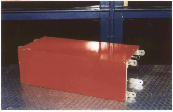
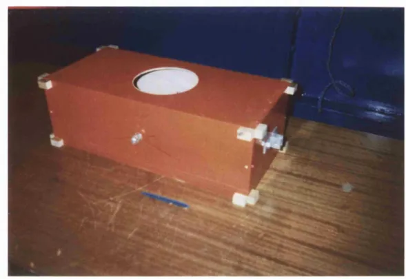
5.1.1 Pontoon model... 93
5.1.2 Potentiometers - data logger... 95
5.2 Experimental procedure...95
5.2.1.2 Test series 2 ... 97
5.2.1.3 Test series 3 ... 98
5.2.2 Mat array... 98
5.2.2.1 Test series 1 ... 98
5.2.2.2 Test series 2 ... 99
CHAPTER 6 DISCUSSION... 100
6.1 Theoretical work by use of constraint equations... 100
6.2 Use of finite element method and potential energy... 101
6.3 Use of a standard FEA package... 103
CHAPTER 7 CONCLUSIONS... 105
7.1 Existing design Software... 105
7.2 Theoretical w o rk ...106
7.2.1 Theoretical work by use of constraint equations...106
7.2.2 Use of finite element method and potential energy...106
7.3 Unlocking solved...107
7.4 Extension to full scale... 108
7.5 Physical models...108
7.6 Mat array... 109
7.6.1 Mat array... 109
REFERENCES... 112
BIBLIOGRAPHY... 120
FIGURES... 121
APPENDICES... 185
APPENDIX A ... 185
APPENDIX B ... 191
APPENDIX C ... 197
APPENDIX D ...203
APPENDIX E ...213
APPENDIX F ...223
APPENDIX G ...227
A Coefficient for the interpolation function
b Breadth of the pontoon
B Coefficient for the interpolation function
BEM Boundary Element Method
C Coefficient for the interpolation function
d Draft of pontoon in still water
D Coefficient for the interpolation function
E Young’s modulus
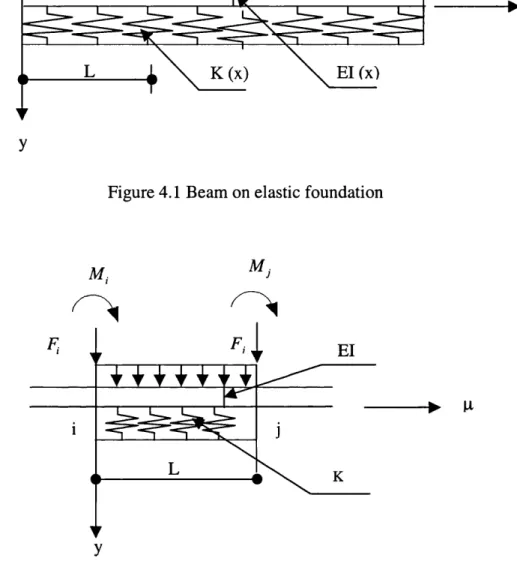
El Bending rigidity
FEM Finite Element Method
F. Force acting at centre of gravity of pontoon
Force acting at centre of gravity of f pontoon in the row
g Acceleration due to gravity
[G] The coefficients of the constraint equation
GMi Longitudinal metacentric height GM, Transversal metacentric height I 2"^ moment of area
K Stiffness due to gravity
L Length of pontoon
M. Hydrostatic moment acting on centre of gravity of pontoon Ml,y Moment acting at centre of gravity of pontoon in the y* row
about the y-axis
M 2ij Moment acting at centre of gravity of pontoon in the row about the x-axis
P, Pontoon number i
Py pontoon in the row
Pr Resultant force
P (x) Distributed load applied on beam r Typical row of the matrix K
VLFS z
Very Large Floating Structure Vertical displacement
Vertical displacement of f pontoon in the •throw
Symbols
a
a i
P
P i
Y Yi e
{AJ
(Aj
P
(Pij
V
Vi
Coefficient for constraint equations Coefficient for constraint equations Coefficient for constraint equations Coefficient for constraint equations Coefficient for constraint equations Coefficient for constraint equations Locking angle between two pontoon
Transformation matrix contains r degrees of freedom Transformation matrix contains (n-r) degrees of freedom Pitch angle of pontoon
Pitch angle of pontoon in the row Density of water
Roll angle of pontoon
1.0 Principal aims
The aims of this work are to consider the behaviour of multipli-connected floating structures, with hinged-rigid connections, due to static and quasi-static loading. The floating structures considered are in the shape of an in-line or a mat array configuration.
There are two main differences between this work and those previously carried out by others in this area. Firstly the type of connection is different from those used in previous studies. In this work the hinged-rigid connection will be considered, whereas in previous works only hinged, elastic or rigid connections have been studied. The second main difference is in the arrangement of the structure, which may consist of multipli-connected floating units in a mat array. In previous works multipli-connected floating structures have been generally considered only in an in-line array.
1.1 Overview
The advent of the next millennium will trigger a wide variety of visionary projects throughout the world. One or more of these could well involve applications of very large floating structures. While research must and will continue to develop better materials, more efficient systems, and economically attractive end products, there are strong reasons to believe that funds can be brought together for major investments in the open ocean. In the past, military interests had the potential to develop such platforms. The end of the Cold War has largely removed this option. Development of VLFS have wide range of motivations such as, national pride, profit, environmental benefits, scientific merit, public works (floating airport, industrial plants and off shore waste disposal) and floating cities.
Other uses of such structures include construction of wave breakers, piers, liquid storage tanks, as well as floating bridges. Although construction of these systems require much more elaborate and sophisticated engineering work, the ideas are similar to those used in building early floating platforms such as bridges, namely, connecting several similar modules in an array consisting of one or several rows.
1.1.1 Connection types
The connection between the constituent units plays a significant role in determining the behaviour of multipli-connected system. The simple connection which had been used in early days has been replaced by more advanced links, which are summarised below:
a) Hinged connections. They are also known as revolute joints for 1-D and a ball joint for 2-D arrays, each model is being joined to the adjacent model. The translational displacement of two consecutive modules at the point of connection is identical, but the angle of rotation (pitch angle) can be different, fig 1.1.
connection and angle of rotation of two adjacent components are the same, fig 1.3.
c) Hinged-rigid connections. The system behaves as a hinged connection, until the angle between two consecutive modules reaches a design threshold value, at which point the system acts rigidly, fig 1.4.
1.2 Applications of multipli-connected floating structures
1.2.1 Wave energy devices
As a result of oil price rises in the mid 1970s, together with environmental concern over the use of fossil fuels serious consideration has been given to the exploitation of alternative energy resources. Wave energy, which is both relatively abundant and benign, has received much attention in industrial countries with appropriate coastlines. The extent, to which this resource is exploited, is currently dependent on the provision of future government and commercial funding. Over the period 1974-79 numerous studies were carried out concerning the utilisation of wave energy. These studies have centred on a number of prototype devices, many of which use some kind of muiltipli-connected floating structure [1-3]. Some examples are shown in figures 1.5 to 1.7.
1.2.2 Wave breakers
the water is too deep, change of the elevation of the water is too great, or the environmental degradation resulting from marina development is unacceptable. To satisfy the demand for moorage, while at the same time overcoming other restrictions, floating breakwaters have been employed at many new marina facilities.
In the 1970s keen interest was shown in the development of floating breakwaters. Several new concepts were studied and more traditional approaches to floating breakwater construction found interesting applications. In many areas of the Pacific Northwest, there were many applications for the floating breakwater and a large number have been installed [4-7]. Some examples are shown in fig 1.8 to
1.15.
1.2.3 Floating marine terminals
Major improvements in port engineering have occurred in the past three decades. Achievement in the fields of port planning, design, construction and operation have been extensively discussed in many technical papers (see for example [8]). During this time there has been a need to resolve port construction and operation problems by using floating wharves. Experiences gained in constructing floating wharves in Peru, Brazil, USA, Saudi Arabia and USSR, clearly shows that under specific conditions (e.g. deep water, strong current, short periods suitable for construction, high change in water level, and construction in remote areas), floating marine terminals can be a competitive solution compared to the fixed waterfront concept. Some floating terminals are shown in figures 1.16 to 1.19.
1.2.4 Other uses
manganese processing plants, airports, and runways each of which is likely to be very large. Description of some of these structures can be seen in [11], for example, runways (Takarada, 1982), entire floating cities (Takarada, 1989), and oil storage (Uki, 1988).
The Times newspaper, October 29, 1995, described a runway, which is planned to be built in the US for future use.
1.3 Objectives of present work
In the work presented herein, the behaviour of multipli-connected floating structures is considered. In particular, the response of the loading is examined. The work advances research in two areas associated with connected floating structures, namely the connection type and the structural arrangement.
1.3.1 Connection type
Previous studies have concentrated either on hinged connections between structures [4-7], [11], elastic, or rigid connections [11]. The present work investigates the hinged-rigid connection. The system behaves as a hinged connection until the angle between two consecutive modules, reaches a design threshold limit, at which point the system acts as a rigid body figure 1.4. This has the advantages of lower displacement in comparison with hinged connections and less moment in the connections in comparison with rigid connections. Further reasons for the selection of this type of connection is given in detail later.
1.3.2 Structural arrangement
connections. The present work has intended to extend the study to the behaviour of systems consisting of arrays of components in single and several rows (i.e. mats).
1.3.3 Hinged-rigid connection as the focus of this study
There were mainly two reasons why this study was focused on the hinged-rigid type connection.
Of the main two types of connections, namely the hinged and the rigid, the rigid connection is widely preferred to the hinged for the basic reason that a structure with such connections has much higher load capacity than the same structure with hinged connection. However to obtain a perfect rigid connection between pontoons is very difficult. This is because of many factors such as manufacturing tolerances and the allowances that are in the connections such that they can be easily assembled on the site in very little time. This gives rise to hinged-rigid connections, which when manufactured were intended as rigid connection, but due to the factors mentioned, slack in introduced in the joint which allows for some hinge action. The fact that this happens more often than not and that previously this effect had not been studied in detail, was the first reason why this type of connection was concentrated on in this study. The objective was that one could predict the effect of the hinged action has on the structure before it is made and thus not only could predict its performance more accurately, but if necessary make modifications to the design in the very early stages of the design process. This is of course preferred to having to make the structure and then experimentally observe the effect of the hinged action on the whole structure. This work from this perspective has a lot of time and money saving potential.
CHAPTER 2 LITERATURE REVIEW
2.1 General
In recent years, multipli-connected structures have gained a noticeable interest among researchers and a lot of work has been carried out in this area. However those dealing with connection types and specially the ones discussed in this work are rare. Given below is a review of the literature from both closely related works and the works that have a more remote relation to this work.
2.2 Review of closely related literature
The work that comes under this heading can itself be further sub-divided into two areas, theoretical studies and experimental work.
2.2.1 Theoretical studies
Adee [4-7] in early work on floating breakwater design considered the wave following impact effect. These studies concentrated on measuring the transmission coefficient of the incident wave, which was found by dividing the transmitted wave height by the incident wave height. In the work it was assumed that both incident wave and the body motions were small.
The work separated the computation of the performance of a floating breakwater into three parts as follows:
I. Formulate equation of motion
- Calculate hydrostatic forces and moments.
- Compute static mooring-line response and calculate forces in the mooring lines.
2. Solve for the waves diffracted by a rigidly restrained breakwater. 3. Sum component to obtain total reflected and total transmitted waves.
In his work, Adee, was less concerned with the actual forms of the floating structures and the method of connecting them and his main objective, as mentioned, was to formulate the transmission coefficient of the wave energy through the structure.
Tsinker [8] described the specifics of multipli-connected floating structures including the following:
1. Chain of pontoons with individual deck sections (Fig 2.1).
2. Linked pontoon system (Fig 2.2), which the forces are shown in connections (Fig 2.3).
3. Redundant pair system (Fig 2.4).
In addition, he also performed some analysis for different models of multipli- connected structures such as a double-cantilever system with suspended intermediate span and continuous beam over pontoons.
He investigated two different methods of connecting the structure together. In one method, the pontoons were connected to each other via hinged connections, and in the second method, a deck was installed on the pontoons, such that the pontoons were connected to each other via the deck, which consisted of sheets connected to each other by a hinged connection.
Piskorski [9] considered a floating pontoon bridge with limited free rotation between the pontoons in one direction. The work divided the pontoon bridge into two separated zones. The contact zone, characterised by the lack of voids between the pontoons (which was considered as a rigid body) and open zones on both sides of the contact zone. The work treated the open zone region as a super element with linear elastic characteristics and considered the vibration in the open zone excited by the concentrated force at its edge. The work utilised Lagrange’s formula but did not consider damping forces.
In his work, Piskorski was more interested in the open zone, whereas the subject of this thesis however is primarily interested in the contact zone and its analysis. He does however suggest some modifications to his formulations if they were to be used to analyse the contact zone.
Although there are some similarities, the formulation that he carried out for the open zone can not to extended for hinged-rigid connections which is the main aim of this work.
Che et al. [10] presented a method for predicting the loading and response of a very large floating structure (VLFS) in regular waves. The motion of a system of integrated modules acted upon by waves was solved. Two-dimensional hydro elastic theory was applied to a VLFS with multiple modules and extended in the longitudinal direction. A modified strip theory was employed to analyse the hydrodynamic coefficients. The mooring system was not considered with the structure, but assumed to remain stationary on location. The system was modelled in two ways. In the first model, the longitudinal sequence of modules was considered to form a single beam having varying shear and flexural rigidities. In the second model, the module was considered to be rigid, that is undeformable as a result of the wave loading. The boundary-element method and Greens function methods were used to obtain a connected system of semi-submersibles.
engineering design of VLFS s.
Their work is good enough for hinged and elastic connections however one can not apply this formulation for hinged-rigid connections.
Takaki and Tango [11] studied both theoretically and experimentally wave drift forces acting on a very large floating structure consisting of multiple barge type modules. The wave drift forces were estimated on the multiple floating structure, linked with rotationally rigid connectors. The effects of wave drift forces on the connector condition and the numbers of bodies were discussed. Three dimensional panel methods were used to determine the hydrodynamic forces with hydrodynamic interaction effects included, and the coupled equations of motion were solved directly. The number of modules was shown to effect the amplitude of motion in head sea conditions. Furthermore the effect of the connecting condition was discussed on the wave drifting forces.
They show that the way the modules are connected together in VLFS (i.e. rigid or hinged) can greatly affect its performance in terms of wave drifting forces. It was shown that for long wavelengths (i.e. when the wavelength to VLFS length ratio, A / L exceeds 4) the hinged structure is considerably more resistant to drifting forces. For smaller wavelengths (A /L < 1 ) both types of structures showed similar behaviours, however for mid-range wavelengths (1< A /L < 3) the hinged connection was considerably more effected by the drifting forces than the rigid structure.
He concluded that it is feasible to assemble large floating platform on the open sea using prefabricated modules configured for rapid ocean transport abroad commercial ships. Further it was pointed out the greatest difficulty in doing this was the relative wave induced motions of the two to-be-connected modules, and that effective control of relative motion and especially relative surge is very important to the entire assembly procedure. To safely and easily assemble the structure, he stated that there needs to be a large separation force maintained within the pontoon array to offset surge forces generated by wave action.
Hatch, Huang and Barthélémy [13] conducted and surveyed the results of a series of sea trails to assess the credibility of a new connection system for joining multiple pontoon barges in elevated seaways. These new connectors and supporting methods of rigging and Joining were designed to reduce and relieve the dynamic loads that occur as a result of relative motion and tug-induced forces.
After pointing out that currently the only commercially used flexible connecting systems are limited almost exclusively to inland waters, they conclude that there is great potential for the new NFESC (Naval Facilities Engineering Service Centre) developed connector system for both commercial and military uses.
Takaki, Lin and Higo [14] studied the motion of a very large floating structure consisting of multiple barge type modules. They used a three-dimensional panel method to determine the hydrodynamic forces taking into account accurately the effect of hydrodynamic interactions among the modules. They also estimated the wave drifting forces on the multiple floating structure with several kinds of connectors (hinged, rigid and elastic).
whereas in the structure with hinged and elastic connectors, the wave drifting force coefficient exceeds the value of 2 around the natural period.
Ohmatsu [15] uses the principle of linear superposition to perform time domain analysis on the hydroelastic response of VLFS in irregular waves. For this he uses the response amplitude operator from the numerical analysis code developed for pontoon-type VLFS with the capability to analyse hydroelastic responses in regular waves of relatively short wavelength. By the same manner he estimates the response to the impact due to dropping objects or landing of aircraft on the VLFS.
He continues to validate the linear superposition theory by use of experimental and theoretical results, and he shows that the theory can also be applied for an elastic response to the short wavelength to a À ! L =0.06, at least. It is also stated that for structures of size less than 5000m, the computation time of this method is smaller than the direct solving method of the equation of the motion in the time domain.
Haeda et al. [16] developed the estimating method of the hydroelastic response of a very large pontoon type floating structure. In this method, the pressure distribution method with shallow draft assumption was used to obtain the hydrodynamic forces considering the elastic motion of a floating body. The elastic responses of very large floating structure were estimated by using 1-D beam modelling. On the other hand, to observe the elastic response of a large pontoon type structure they carried out experiments in head sea and head-beam sea conditions. The experimental model was an elastic model of pontoon type large floating body.
the effect of the bending stiffness can be neglected. In the wave frequency range of A / I >0.067, considering the difference of the vertical displacement related to the bending stiffness, it may be concluded, they state, that smaller bending stiffness is rather advantageous.
Sannasiraj et al. [17] used finite-element techniques to study the diffraction/radiation boundary value problem arising from the interaction of oblique waves with a freely floating structure. Further, the hydrodynamic behaviour of two-dimensional horizontal floating structures under the action of multi-directional waves has been studied. They use the linear transfer function to determine the wave exciting forces and motion responses of a structure of finite length in short-crested seas.
Lee and Newman [18] present a computational analysis for the effect of waves on very large hinged vessels consisting of several modules, connected by simple hinges. They consider two generic types of modules, rectangular barges and semi- submersible. The results presented include computation of the vertical motions, structural deflections, and hinge shear forces in head and oblique waves, for a configuration with 5 modules each of length 300 metres. To permit a quantitative assessment of the importance of hydroelasticity, a range of structural stiffness parameters were considered.
The results demonstrate that it is feasible to analyse linearized wave interactions for several interacting semi-subs. They also characterised the hydroelastic effect with the non-dimensional stiffness parameter S. Based on Length L=300m for each module, they find that hydroelastic effects are important in the range 10“"^ <S < 1 0 ^ however for larger values of S the structure is effectively rigid. For smaller values of S the structure behaves like a completely flexible monohull.
hydroelasticity, which can be used to determine the motions and intermodule forces of a multi-module VLFS. Their method is applicable to an arbitrary geometric layout of the modules, but to simplify the work, the modules considered were all rigid and thus meaning that all deformations occur in the module connectors. The procedure was used to analyse the response of a 5-module VLFS in both regular and irregular waves.
Their results indicate that for VLFS, the fluid coupling of the modules is relatively weak. However, the mechanical coupling through connectors can have a significant impact on the motions. If the connectors provide substantial resistance to the relative rotations of adjacent modules, then the vertical and rotational (pitch) motions are substantially reduced compared to the motions for a single module. However, if the connectors do not provide sufficient rotational stiffness, the module pitching can be dramatically increased compared to the motions of a single module.
2.2.2 Experimental work
Endo et al. [21] carried out analysis on experimental models to estimate the modal properties such as natural frequencies, damping ratios, and mode shapes for a unit- linked large floating structure model. Fluid-structure coupled vibration tests were carried out. The experiment was performed by hitting the force transducers arranged on each unit with an impact hammer made of soft rubber. A number of models, namely one, two, and eight unit linked models, were used in the study. Each unit consisted of a rectangular prism connected to each other by steel plates. A floating model was anchored by two spring-wires on the base edges of each unit. Fig 2.5.
The vertical acceleration responses were measured on the upper surfaces of the model by arranging acceleration sensors on each unit. The transfer functions defined by normalised input and output data were established. The modal properties such as natural frequencies, damping ratios, and mode shapes were estimated by carrying out curve fitting of the transfer function obtained in the vibration tests
Furthermore, the two-dimensional formulation of fluid-coupled free vibration analysis with the aid of the BEM (Boundary element method) was used to take into account fluid-structure interaction. The coupled natural frequencies and the corresponding mode shapes were obtained and compared to the experimental data.
These papers discuss issues, which are more distantly related to this work, and only the most relevant are considered here.
2.3.1 Design philosophy of VLFS
Suzuki and Yoshida [22] write about how a large floating structure is characterised by its significant elastic response. They present discussion on the elastic response and design of the structure. General dynamic response characteristics are shown, and according to the understanding of the elastic behaviour a new type of the structure whose perimeter structure is modified to suppress excessive response is proposed. Secondly the authors propose a structural type whose redundancy and safety are augmented. They introduced mechanical connectors to the structure and the whole structure was constructed from independent element floating structures, which were connected, to each other by the mechanical connectors. They also state that the safety of the structure in the construction stage can also be improved by this method.
Takarada [23] discusses the fact that much progress has been made over the last 20 years on construction technologies for very large floating structures, and that we have reached the stage where we are now able to safely and economically build such structures. Here, in the interests of making the structures even better, the author presents a few very short comments relating to the control of environmental conditions and to the combination of structural types and human factors.
by the authors. The authors also point out that the design philosophy and methodology for floating and submerged tunnel bridges draws heavily on Norwegian experiences in two large fields. Namely: (1) offshore structures, and (2) conventional bridges.
He concludes very briefly that the long life of most VLFS will depend on no more than 7 factors, namely, careful attention to areas such as
• Met-ocean data Loads
Materials
Proper application of well formulated design rules Design analysis and verification
Careful construction and quality assurance
Planned maintenance and instrumented verification of behaviour.
system.
He draws his work to a close by categorising the VLFS maintenance into three purposes of structural, social, and functional. To satisfy the three purposes mentioned he states the maintenance system is to be consisted of three parts, which are the main part, databases and evaluation committee. The function of an evaluating committee would be to evaluate all the maintenance activities, initial deterioration estimation, modification method of gap between evaluated and observed deterioration and decision on the end of service period based on the condition of the end of service defined in advance.
Yutaka [26] discusses two main proposals that were given in the two phases of the completion of the Kansai International Airport (KIA). The first proposal was for a semi-submergible type of floating structure, however this was later overshadowed by a proposal for box-shaped pontoon with breakwaters around it to compete economically with land reclamation. He also conducts surveys from expected future users of these structures.
2.3.2 Example of conceptual design
Maeda et al. [27] aim to tackle the problem of adopting a VLFS for use as a base for power generation. Two main structures are put forward, the semi-submergible and the pontoon boxes. The idea will be mainly developed for renewable energies such as solar heat and light, wave, wind and OTEC (Ocean Thermal Energy Conversion). The authors further go on to make suggestions as to how make these plants more economically competitive with non-renewable power sources.
anchor legs at the stem. This mooring configuration ensures minimal movement of the pierhead at the bow where it must interface with the fixed approachway, but allows the pierhead to be rotated over an arc of ninety degrees, forty-five degrees to either side of the initial orientation, with the SPM defining the rotation point. The final link in the system is the approachway system, built of individual pile supported spans each nominally 60 feet long, 24 feet wide and 7 feet deep, which provides a fixed, elevated roadway connecting the pierhead to the shore.
Young Chung and Hoon Chung [29] develop key technologies for the design and fabrication of floating barge systems for various kinds of plants such as desalination plants, waste-treatment plants, etc. The work also includes research on the floating breakwater systems for mitigation of wave and current loads on floating plants.
Blood [30] puts together a report on the modelling and testing of a Pneumatically Stabilised Platform. A 1:22.85 scale model of a proposed 100 x 300 foot prototype Pneumatically Stabilised Platform (PSP) was constmcted and tested to gather data to confirm the accuracy of the hydrodynamic and structural design tools under development. Because it was impractical to scale atmospheric pressure, the tests were limited to confirmation of the "air pocket factor," a parameter relating hydrostatic stiffness to the compressibility of air, and the gathering of rudimentary data on air movement, stability, and wave attenuation. After conducting a series of tests he concludes that the modelling was successful.
wave breaking structure around that main body. He proposes a wave breaking structure, which can reduce wave effect and elastic deformation of the main body. The SRI VLFS has the claimed advantage of less construction and maintenance cost of pontoon type structures and also the advantage of better wave damping capability, associated with semi-submersible structures.
2.3.3 Strength and reliability
Okada et al. [32] provide a structured reliability assessment method for fatigue strength of large-scale marine space structures under non-linear and irregular wave induced loads by using a varying load simulation technique. The applicability of the method is investigated through numerical examples successively applied to hybrid type structures with floating bodies and supporting foundations under some irregular sea state conditions. After conducting some tests they deduced that the effect of the number of supporting foundations on the reliability level is remarkable for large significant wave height.
Endo and Yago [33] in their work, perform a case study in order to try and determine the statistical maximum wave-induced load that a given pontoon will be subjected to. They produce their results based on short-term and long-term predictions and their method takes into account the modelling error and the uncertainty of the load. They come to the conclusion that the given pontoon (300x60m) has no problem when subjected to a 100-year-retum wave load.
The main conclusions of this work were that, the influence of a Poisson’s effect of deck and bottom plating on the calculated results is small and that the coarser mesh model gives the smaller deformation.
2.3.4 At-sea construction and maintenance technologies
Nakano, Kinoshita and Kozai [35] produce a report on the modelling of an ultra large floating structure. The model was constructed by joining 9 massive floating module blocks in open-sea conditions. During the completion of the 300 Maniar 60x2m model, several experimental procedures were attempted. These included water sealing, the application of a work vessel to access the bottom of the model in water and welding of the bottom plates on one side and both sides. At the end the authors consider these new procedures to be effective and useful in the fabrication of real ultra large floating structures.
Okubo et al. [36] describe a method of estimating the forces acting on joints between floating units when they are connected at sea. An important process in the construction of pontoon-type floating units now being proposed for use in off shore floating airports. Since the height-to-length ratio of prefabricated floating units is smaller than that of conventional small-scale floating structures, the enhanced effect that elastic deformation has on these forces is a matter of concern. They investigated this issue through experiments on a model subjected to wave motion in a water tank. The forces acting on inter-unit joints, the vertical displacement of the units, and the strains in the units were measured. The response characteristics of the forces were studied while the units were subjected to wave motion and the relationship between the forces and elastic deformation in higher-order modes was clarified from these measurements.
(computational) was confirmed by comparison of some results with experimental data, a series of computational studies were conducted to examine the effects of varying inter module connector location and structural stiffness on the predicted forces of constraint between floating structural modules. Several sea states were considered. Relative displacements and forces of constraint were computed.
2.3.5 External loads and response analysis
Faltinsen [38] in this work has derived an estimate of local stresses due to bottom slamming on a floating airport. This is related to wet deck slamming on multihull vessels and theoretical and experimental results from drop tests of horizontal elastic plates of steel and aluminium on regular waves. He remarks that the results from the experiments agree well with the numerical computations and that this study reveals, both numerically and experimentally, that the slamming induced local stresses are highly influenced by dynamic hydroelastic effects. The maximum bending stresses are not sensitive to where the waves hit, or to maximum pressures. He further adds that measured maximum pressures are very sensitive to external conditions and cannot be used as a measure of maximum local bending stresses.
The work concludes that the maximum stress is proportional to the impact velocity and is not sensitive to where the waves hit the plate. It is also shown that the maximum stresses decrease with increasing the values of L/R, where L is the plate length and R is the curvature radius of the wave crest. Also the linear dependence between the maximum stresses and the impact velocity makes it possible to use the statistical properties of the impact velocity in a sea state to express the extreme values for the maximum local slamming induced stresses in the wetdeck of a multihull vessel.
The occurrence of slamming of the VLFS depends on the extent of the bottom emergence and the rising speed of the relative wave height at the bow. The peak values of the impact pressure components depend on the rising speed of the relative wave height at the bow.
In the case of the model with low rigidity, its extent of the bottom emergence is smaller than the high rigidity. However, the rising speed of relative wave height at the bow of the model with low rigidity becomes larger due to its large elastic response, so that the large impact pressure occurs.
Takagi [40] in this work, theoretically and experimentally, discusses elastic deformations and the mooring force of 8 very large floating bodies with tsunami waves. The theory was based on a shallow water wave theory and the matched asymptotic expansion method and the modified Boussinesq equations were employed for the representation of long waves beneath a floating elastic plate which was a simplified model of the very large floating body in tsunami waves. Measurements of the elastic deformation and the mooring force of floating elastic plate with the solitary wave were also carried out.
It was concluded that the experimental results of the elastic deformation and the mooring force are in very good agreement with those of the theoretical simulation. Hence it was confirmed that the theoretical simulation is accurate enough as a design tool of the very large floating body against the excitation due to tsunami waves.
Ohkusu and Nanba [42] in this work present a new method to analyse the response of a thin elastic plate of large horizontal size floating in waves. Huge horizontal size and small thickness are typical of the recent designs of floating airport. A benefit of this new method is that one does need not the modal analysis of the body motion. Furthermore, the solution of a hydrodynamic boundary value problem and the solution for the body motion including the elastic deflection are simultaneously obtained.
They present an efficient method to predict the elastic deflection of a very large platform of thin plate configuration in waves. A thin elastic plate floating on the free surface is interpreted as a part of the free surface and this free surface motion is itself the deflection of the plate. The problem is considered as a boundary value problem in hydrodynamics rather than the determination of the elastic response of the body to hydrodynamic action. It was demonstrated that correct understanding of the hydroelasticity of the platform is attainable with this approach. Simpler numerical implementation of the phenomena will be a benefit of this approach. This has applications such as predicting the complicated hydroelastic behaviour of very large platforms like floating airports in waves.
Kashiwagi [43] work revolves around two new ideas. First a new calculation scheme is described for the pressure distribution method, giving directly the pressure on the bottom of a VLFS with shallow draft. This method also utilises bi cubic B-spline functions for representing the unknown pressure and a Galerkin method for converting the integral equation into algebraic simultaneous equations. Secondly he proposes a mode-expansion method for solving the vertical vibration equation of a rectangular plate. He backs up his methods with confirmation of the results matching known experimental cases
hydrodynamic pressures exerted on it are evaluated by combining the pressure distribution method and the dry-eigenmodes. Wave-induced motions of the plate are expressed as a superposition of the dry-eigenmodes, and the principal co ordinates are finally determined by solving a set of equations of motion. They verify the modal analysis through comparisons of calculated amplitudes of vertical motions and instantaneous shapes of a plate model in head seas with available measured data. They show reasonable agreements. Then they applied this method to a large floating module of 300mx60m, and investigated its motions and disturbance waves around it in head and quartering seas. Finally, response amplitude operators of its first 10 modes in all heading waves with various wavelengths are shown in their work.
Kagemoto et al. [45] in this work propose a method whereby one can predict hydroelastic behaviours of a very large floating structure. By dividing the structure into a number of small structures and the continuous deformation of the structure is represented by the succession of the discrete displacement of each small structure. Each structure is treated as if it were an independent floating body while the structural constraints are taken into account as additional restoring forces on its motions. The hydrodynamic interactions among the divided structures are accounted for in the evaluation of hydrodynamic forces once their complex motion amplitudes are known. The motion amplitudes are, in turn, determined from the equation of motions, which are excited by the hydrodynamic forces. Therefore by solving the equations of hydrodynamic interactions and those of motions simultaneously, the hydroelastic interactions are properly accounted for and the motions of each small structure, which represent the local behaviours of the total VLFS, are determined in one computation.
the dynamic behaviour of stationary and neutrally buoyant barge type (i.e. rectangular box) structures in waves. Beam and plate finite element (FE) models are used to describe the dynamic characteristic of the barge in vacuo. A potential flow model, whereby the wet surface of the barge is discretised by rectangular panels containing a source at their centre, is used for the wet analysis. The effects of barge size and flexibility on the use of different FE idealisations and the wave- induced loads are discussed
Inoue, Zhang and Tabeta [47] put forward a linearized analysis of the hydrodynamic forces on the very large floating structure in waves. The hydrodynamic interactions of the elastic deformations and the hydrodynamic external forces are also discussed. The motion responses and wave drift forces of a floating airport is investigated. They also carry out numerical simulations by means of a multilevel model to discuss the interaction of ocean currents and a large floating structure in a bay.
Quanming et al. [48] present the time simulation of motion responses of a moored VLFS in waves. The equations based on Cummins’ concept of impulse responses are employed, and solved in the time domain by using Adams prediction- correction method. They obtain hydrodynamic coefficients and first order wave- exciting forces involved in the equations from a three-dimensional potential theory in the frequency domain. The second order wave drift forces and the non linear mooring forces are also taken into account. The numerical results of a multi-module large floating structure consisting of five identical semi- submersibles responding to waves with three incident wave angles and two sea states are illustrated
floating structure. The floating structure is treated as a rectangular flat plate by use of finite elements, and boundary elements are used in the formulation of the sea region.
Riggs [50] in this work derives the hydrostatic stiffness coefficients for flexible floating structures. The formulation includes the hydrostatic pressure term as well as the effect of the structural (i.e., gravity) loads. Riggs finds that the hydrostatic term agrees with a formulation presented previously by Newman. The advantage of the present formulation is that it also includes the structural loads, as well as providing an alternative equivalent expression for the hydrostatic terms. The results are useful both in hydroelastic analyses as well in finding the deformations in the static equilibrium position. Riggs presents several examples to investigate the magnitude of errors that result from certain simplifications, which are sometimes used, in the determination of the hydrostatic stiffness, such as ignoring the gravity loads.
The result of this work was the derivation of formulation for the hydrostatic stiffness coefficients of flexible structures, which includes the effect of both the hydrostatic pressure as well as the structural gravity loads. The formulation was used to investigate the impact on the stiffness coefficients of common simplifications often used in hydroelastic analyses. In particular, it was found that ignoring the volumetric strain could result in significant errors in the stiffness coefficients. The errors, introduced by ignoring Poisson’s ratio are directly proportional to the ratio. Depending on the value of an effective Poisson’s ratio for practical, built-up structures, it was shown that the errors may be of the same order as the correct coefficients.
large; the dynamic responses with the effect of the added-mass are reduced compared with those without considering the effect of the added-mass.
Ueda et al. [52] in their work establish a computational analysis method to calculate motions, mooring forces, deformations and working stresses of floating bridges subjected to wind and waves.
Shiraishi et al. [53] in their work evaluate the effect of the incident wave direction, wave height, wave period and rigidity of the floating body on the characteristics of the motion and the deformation of long flexible floating structures. Hydraulic model tests were also carried out and the results were analysed.
2.3.6 Mooring technology
Sekita et al. [54] deal with the motion response analyses of fluctuating winds and seismicity including the deformability of mooring dolphin structures required for rare intense loads. This work also discusses the functions required of shock absorbing mechanisms indispensable to mooring facilities such as mooring dolphin.
2.4 Standard package
2.5 Review Summary
As has been shown in this chapter, many associated studies have been conducted in this field previously. While all of these were considered on multi-connected structures and VLFS, only one paper [9] was related to work on hinged-rigid type connections. However even in this work, Piskorski [9] considered the floating pontoon bridge with limited free rotation between the pontoons in only one direction. He divided the pontoon bridge into two separated zones. The contact zone, characterised by the lack of voids between the pontoons (which was considered as a rigid body) and open zones on both sides of the contact zone. The work presented in this thesis differs from his in that here it is primarily interested in the contact zone and its analysis, while Piskorski was more interested in the open zone. Hence as can be seen there is a real absence of work and studies done in this particular field which highlights the need for such studies.
FORMULATION
3.1 Introduction
To determine the displacements of joints, in order to be able to calculate the stresses occurring in the members, the stiffness of the structure must be evaluated. The stiffness of a multipli-connected floating structure can be divided in two components, the structural stiffness and the hydrostatic stiffness. This chapter discusses theoretical work carried out to find the hydrostatic stiffness matrix of a multipli-connected floating structure based on the hydrostatic stiffness matrices of individual pontoons.
3.2 Constraint equations
Constraint equations provide relationships between degrees of freedom that are supplemental to the relationship represented by the basic stiffness equations. Constraints arise in many cases, including the multipli-connected floating structure, in particular analysis methods of incompressible materials, treatment of special boundary conditions and in attempts to impose specified patterns of displacement over certain portions of the structure. A number of these situations will be discussed later in this text.
3.3 In-line array
3.3.1 Basic hydrostatics
In order to be able to find the displacement of the joints, one first has to evaluate the modified stiffness matrix. To do this, the constraint equations are inserted into the basic equations of equilibrium. The following is the mathematical representation of the above statement.
The equilibrium equation for the quasi-static response of a multipli-connected structure with several pontoons connected in an in-line configuration can be written as:
= (3.1)
The static equation for any individual pontoon (considered as wall sided and with symmetry in the y, z plane Fig 3.1) can be written as:
A 0
0 B (3.2)
A = pgLb (3.3)
B = pgLbdGM, (3.4)
Where, p is density of water
g is acceleration due to gravity
L is length of pontoon
z is vertical displacement 0 is pitch angle
GM^ is longitudinal metacentric height
F is force acting at centre of gravity of each pontoon
M is hydrostatic moment acting on centre of gravity of each pontoon
The static equation for two identical pontoons besides each other without any connection may be written as:
'a 0 0 O' z,
0 5 0 0 0, M,
0 0 A 0
0 0 0 5 A . M2
(3.6)
3.3.2 Extension of the models for an in-line array
The expanded equation for n pontoons without any connection becomes as follows:
~A 0 0 0 ••• • . ... 0 0 0 O ' 0 5 0 0 • • • . ... 0 0 0 0
0 0 A 0 ••• • . ... 0 0 0 0
0 0 0 5 • • • . ... 0 0 0 0
0 0 0 0 ••• • . ... A 0 0 0
0 0 0 0 ••• • . ... 0 5 0 0
0 0 0 0 ••• • . ... 0 0 A 0
0 0 0 0 ••• ' . ... 0 0 0 5
Zi
M,
Z2 F2
M2
Z„-i
3.3.3 Constraint relationship
In general and in rather complicated form the constraints equation can be written as follows:
x^=a-\- (3.8)
Where, j = = 7 +1, ^ ^ +1
The constraint equation (3.8) is inserted into equation (3.7). For simplification equation (3.7) may be rewritten as [55]:
YjsM.IXI + K,tX„ + K„x, = p , (3.9)
Where, r is any row of the matrix K Pr is the resultant force
Substituting equation (3.8) for x - in equation (3.9) gives:
^ r s ^ s ^ r i ^ i + l P^i+2 ^ri+] ^ri+2^i+2 ^ri+3^i+3 ~ P r (3.10)
Factorising (eqn. 3.10) we have:
K r,X ^ + ( ^ „ + ^ri+ l)^i+ l + ( y ^ r i + ^ri+ 2)^i+ 2 + + ^ri+3)^i+3 = P r ~ ^ r i = ^ r
(3.11) Due to its nature the above operation has removed the symmetry in the coefficient matrix K. This can be reinstated by:
f row
+)8K:„ + ) ^ ,, + 2i r , , x
+ iPW^^ii + = A , + ^i
(3.12) row
iy^is
+
)^s
+
^y^ii
+
)^ij
+
P^ki
+
^kj )^j
+
+
)^ik
+
y^ki
+
^kk )^k
+iyy^ii + + y ^ k i+^ki )^e - yji +
(3.13) row
(y/K.^ + )%, + {wPK^■ + yKy + + K^. )Xj + {yy/^a + + yf^a + )^k
+ (y/^K-. + y/K.^ + y/K(. + = y/q^ + q^
(3.14) Thus the matrix regains its symmetry.
In the above matrix there is no column. It is possible then to insert the constraint equation (3.8) in place of the row. After multiplication by Ku we have:
- K^.Xj + PK.^Xj + yK^^x^ + y/K^^x^ - -ccKii (3.15)
Recalling that the stiffness matrix K is symmetric, the column must be completed with /3K-.x^ in the row:
0 = PK--X- — PK-. {cc + pXj + yKj^ + y/x^ ) (3.16)
Finally the corrected rows have the following form:
f row
+i^^ik + y^ji + ^jk)^k
+ (/3k + y/Kj. + Kjf, )Xg = pq^ + qj + apK^^ (3.17)
row
iy^is + ^ks)^s + (yK^J + + K ^)xj + (yK.^ + yK^^ + K^P)x^
+ ()K., + y/K,, + )x, = yq. + ^, + ayK, (3.18)
row
(yrKi^ + K^^)x^ + WK^x^ + {y/K^■ + /3K^^ + K^pxj + (y/K^^ + yK^^ + )x^
+ (y/K-f + y/K^^ + K^^ )Xf = y/q^ +qg+ ay/K^■ (3.19)
Now we have obtained an expression for the modified stiffness matrix. This is the theoretical model for n pontoons. In the following section the above method is employed in the different cases.
3.3.4 Connections
3.3.4.1 Hinged
Using Fig 3,2, small angle identity and basic geometric relationships, the constraint equation for hinged-connections for the above system becomes:
z, + 0; +" ■L + L, 2
A
0M = Zm (3.20)
(l +l,
Z/ = - + ^, + 1 - (3.21)
This can be written as:
Z i= a + (3.22)
Where:
« = 0
L + Z/j
2 r = i
L + Lj
L, is distance between two pontoons
L is length of pontoon
Combining equations (3.15), (3.17), (3.18) and (3.19) with equation (3.6) will result in the modified matrix for the two pontoons:
Please note the following substitutions;
X,. = z, Xj = x^= Z2 = ^2
i = \ y = 2 X: = 3 Z = 4
From equation (3.15) the row becomes
— Azj + + )Az2 + ~ ~GcA (3.23)
From equation (3.17) t h e r o w becomes
From equation (3.18) the row becomes
yAz^ + 0 + Azj + 0 = F2 + + ayA (3.25)
From equation (3.19) the row becomes
y/Az^ + 0 + 0 + = M ^Fj + ccy/A (3.26)
Equations (3.23 to 3.26) can be written as (3.27). This is the modified matrix for a system comprising two pontoons.
(3.27)
- A PA yA y/A - o A
pA B 0 0 0, Ml + pp^ + apA 0 A 0 F2 + yF^ + ayA
y/A 0 0 B A . M2 + y/F^ + ay/A
Adding a third pontoon to the two pontoons configuration will result in (3.28).
“- A PA yA y/A 0 O' - o A
PA B 0 0 0 0 0, M ,+ P F , +apA
yA 0 A 0 0 0 Z2 F2 + /Fj + ayA
y/A 0 0 B 0 0 0 2 M2 +y/F^ +ay/A
0 0 0 0 A 0 Z3
0 0 0 0 0 B .^3. ^ 3
(3.28)
Please note the following substitutions;
X, = z ,,6'i X, = z, 5 = 1,2 / = 3
Xj - 0^ 7 = 4
=^2
k = 5
- O2
i = 6
From equation (3.15) the row becomes
— A%2 + ^4^2 + if/AO-^ = —(xA
From equation (3.17) t h e r o w becomes
{yPA + yfA)z^ + 0 + PAz2 + B6 2 + 0 + 0 = (M 2 + + ay/A) + P{F^ + ayA) (3.30) From equation (3.18) the row becomes
+ 0 + yAz2 + 0 + Az3 + 0 = F3 + y(F^ + yF^ + ayA) (3 31)
From equation (3,19) the row becomes
yy/Azi + 0 + y/Az2 + 0 + 0 + B6^ = ^3+ ¥ ( ^ 2 + YF^ + o # ) (3.32)
Bearing in mind equations (3.29) to (3.32), and matrix symmetry, the equation for a system with three pontoons can be written as follows:
- A PA 0 yPA + y/A y^A yy/A
PA B 0 0 0 0
0 0 - A PA yA y/A Zz
yPA-vy/A 0 PA B 0 0
y^A 0 yA 0 A 0 Z3
yy/A 0 y/A 0 0 B ^ 3.
- o A
Ml +ySF, +apA
- o A
(M2 + + ay/A) + P(F2 + )Fi + ayA)
F3 + y {F2+ yF^ + ayA)
M3 + y/(F2 + yF^ + ayA)
(333)
The operation is also applicable for n pontoons with hinged connections, however the algebra gets tedious for more than 3 pontoons. Hence subroutine COND in programme HINGE was written to calculate this.
3.3.4.2 Rigid
For rigid connections, the additional constraint equation is:
6), =6),+, (3J4)
or
6i = a^+ (3.35)
where, ai=0 , Pi=0 and Yi=1
Combining equations (3.15), (3.17), (3.18) and (3.19) with equation (3.27) will result in the modified matrix for the two pontoons:
Please note the following substitutions;
= z, X- = 6 ^ — ^2 ^ k ~ ^ 2
5 = 1 i = 2 y = 3 k = 4
From equation (3.15) the row becomes
-fiA 0 ,+ O + PAO^ = -a ,p A (3.36)
From equation (3.17) the row becomes
yA z^+ ^^ A z2 = F ^+ )^^+ ayA (3.37)
From equation (3.18) the row becomes
+ y/A^Zi BO^ + 0 + B02 — (3/j + pp^ + ccPA) + {M^ + W^\ F (3.38)
- A 0 yA
0 B 0
yA 0 A
PA + y/A B 0
B 0
B
0,
Z2 A
- o A — cc^B
F2 + yF^ + ayA
{M. j + ySFj + ccfiA) + {M.2 + y/F^ + ccy/A) (3.39)
The operation is also applicable for n pontoon with rigid connections, however the algebra gets tedious for more than 2 pontoons. Hence subroutine COND in programme RIGID was written to calculate this.
3.3.4.3 Hinged-rigid
In the case of the hinged-rigid configuration the constraint equation is:
(3 35)
The above constraint inequality can be separated into two;
P/+1 P/+1
(3.36) CT37)
3.3.5 Results for in-line array
The calculations for an in-line array (section 3.3) were coded in software and are included in the following appendices:
Appendix A, Program Hinged, for hinge connection Appendix B, Program Elastic, for elastic connection Appendix C, Program Rigid, for rigid connection
Appendix D, Program Hinge-Rigidl, for hinged-rigid connection in one direction
Appendix E, Program Hinge-Rigid2, for hinged-rigid connection in two directions
The following table gives the values of the individual pontoon parameters used in the experimental studies. The same parameter values were also used in the above programmes so that a comparison could be made between the theoretical and experimental results. The details of the experiments are given in Chapter 5.
Parameter value
Length Width Height Draft Mass
Hinged-Rigid angle
0.6 m 0.28 m 0.2 m 0.03 m 5.04 kg 0.011765 rads 0.674 degrees
Table 1
![Figure 1.11 Schematic drawing of module connection, Port Orchard, Washington Floating breakwater [6]](https://thumb-us.123doks.com/thumbv2/123dok_us/8609266.1398974/126.892.24.766.70.1145/figure-schematic-drawing-connection-orchard-washington-floating-breakwater.webp)